Service Manual
Page 46
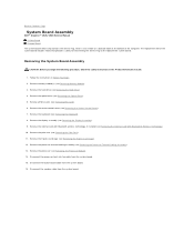
... replacement kit for the system board includes media that provides a utility for transferring the Service Tag to Contents Page System Board Assembly Dell™ Inspiron™ 1525/1526 Service Manual S-Video Board Charger Board The system board's BIOS chip contains the Service Tag, which is also visible on a barcode label on the bottom of...
... replacement kit for the system board includes media that provides a utility for transferring the Service Tag to Contents Page System Board Assembly Dell™ Inspiron™ 1525/1526 Service Manual S-Video Board Charger Board The system board's BIOS chip contains the Service Tag, which is also visible on a barcode label on the bottom of...
Service Manual
Page 49
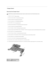
... Removing the Palm Rest). 11. Carefully disconnect the charger board connector from the system board and seperate charger board from the system board assembly. 1 screws (2) 2 charger board connector 3 charger board 4 system board Charger Board Removing the Charger Board CAUTION: Before you begin the following procedure, follow... the safety instructions in Before You Begin. 2. Remove the two screws securing the charger board to the system board assembly. 16. Remove the processor thermal-cooling assembly (see Removing the Optical Drive). ...
... Removing the Palm Rest). 11. Carefully disconnect the charger board connector from the system board and seperate charger board from the system board assembly. 1 screws (2) 2 charger board connector 3 charger board 4 system board Charger Board Removing the Charger Board CAUTION: Before you begin the following procedure, follow... the safety instructions in Before You Begin. 2. Remove the two screws securing the charger board to the system board assembly. 16. Remove the processor thermal-cooling assembly (see Removing the Optical Drive). ...
Service Manual
Page 50
Replace the two screws securing the charger board to Contents Page Back to the system board assembly. 3. Follow the steps in Removing the Charger Board in the Product Information Guide. 1. Replacing the Charger Board CAUTION: Before you begin the following procedure, follow the safety instructions in the reverse order. Align the charger board to the system board in the right direction and gently press to connect the charger board connector to the system board. 2.
Replace the two screws securing the charger board to Contents Page Back to the system board assembly. 3. Follow the steps in Removing the Charger Board in the Product Information Guide. 1. Replacing the Charger Board CAUTION: Before you begin the following procedure, follow the safety instructions in the reverse order. Align the charger board to the system board in the right direction and gently press to connect the charger board connector to the system board. 2.

