Installation Guide
Page 2
D-Link DXS-3250/DXS-3227P/DXS-3227 User Guide Table of Contents Preface...5 DXS-3250/DXS-3227P/DXS-3227 User Guide Overview 6 Intended Audience ...7 Device Description ...9 Viewing the Device...10 Ports Description...12 Cable Specifications...14 LED ...Preparing for Installation ...22 Installing the Device ...24 Connecting the Device ...27 Initial Configuration ...29 General Configuration Information 29 Booting the Switch ...30 Stacking Configuration ...32 Configuration Overview...33 Advanced Configuration...36 Software Download and Reboot 39 Startup Menu Functions ...41 Getting Started...45...
D-Link DXS-3250/DXS-3227P/DXS-3227 User Guide Table of Contents Preface...5 DXS-3250/DXS-3227P/DXS-3227 User Guide Overview 6 Intended Audience ...7 Device Description ...9 Viewing the Device...10 Ports Description...12 Cable Specifications...14 LED ...Preparing for Installation ...22 Installing the Device ...24 Connecting the Device ...27 Initial Configuration ...29 General Configuration Information 29 Booting the Switch ...30 Stacking Configuration ...32 Configuration Overview...33 Advanced Configuration...36 Software Download and Reboot 39 Startup Menu Functions ...41 Getting Started...45...

Installation Guide
Page 4
D-Link DXS-3250/DXS-3227P/DXS-3227 User Guide Defining Multicast Bridging Groups 170 Managing System Files...174 File Management Overview ...175 Downloading System Files...17 Uploading System Files ...177 Activating ...
D-Link DXS-3250/DXS-3227P/DXS-3227 User Guide Defining Multicast Bridging Groups 170 Managing System Files...174 File Management Overview ...175 Downloading System Files...17 Uploading System Files ...177 Activating ...
Installation Guide
Page 5
Table of Contents Viewing Statistics ...249 Viewing Interface Statistics...249 Managing RMON Statistics ...257 Appendix A Technical Specifications 264 Appendix B Cables and Connectors 267 Appendix C Troubleshooting 269 Problem Management ...270 Troubleshooting Solutions ...270 Warranty ...273 Product Registration ...276 Contacting D-Link Technical Support 277 International Offices...304 Page 4
Table of Contents Viewing Statistics ...249 Viewing Interface Statistics...249 Managing RMON Statistics ...257 Appendix A Technical Specifications 264 Appendix B Cables and Connectors 267 Appendix C Troubleshooting 269 Problem Management ...270 Troubleshooting Solutions ...270 Warranty ...273 Product Registration ...276 Contacting D-Link Technical Support 277 International Offices...304 Page 4

Installation Guide
Page 6
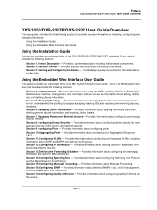
... easy-to help system administrators monitor network performance. In addition, The D-Link Embedded Web Interface provides real time graphs and RMON statistics to -navigate. D-Link DXS-3250/DXS-3227P/DXS-3227 User Guide Preface The Embedded Web System (EWS) is a network management system. The D-Link Embedded Web Interface configures, monitors, and troubleshoots network devices from a remote...
... easy-to help system administrators monitor network performance. In addition, The D-Link Embedded Web Interface provides real time graphs and RMON statistics to -navigate. D-Link DXS-3250/DXS-3227P/DXS-3227 User Guide Preface The Embedded Web System (EWS) is a network management system. The D-Link Embedded Web Interface configures, monitors, and troubleshoots network devices from a remote...
Installation Guide
Page 7
...Using the Installation Guide This section provides an overview of Service - Configuring Device Security - Configuring Quality of the D-Link DXS-3250/DXS-3227P/DXS-3227 Installation Guide, which includes the following sections: • Section 1. Getting Started - Defining the Forwarding Database ...6. Configuring Ports - Configuring Multicast Forwarding - Preface DXS-3250/DXS-3227P/DXS-3227 User Guide Overview DXS-3250/DXS-3227P/DXS-3227 User Guide Overview This user guide is divided into the following sections to the D-Link Web System Interface User Guide. Provides a system ...
...Using the Installation Guide This section provides an overview of Service - Configuring Device Security - Configuring Quality of the D-Link DXS-3250/DXS-3227P/DXS-3227 Installation Guide, which includes the following sections: • Section 1. Getting Started - Defining the Forwarding Database ...6. Configuring Ports - Configuring Multicast Forwarding - Preface DXS-3250/DXS-3227P/DXS-3227 User Guide Overview DXS-3250/DXS-3227P/DXS-3227 User Guide Overview This user guide is divided into the following sections to the D-Link Web System Interface User Guide. Provides a system ...

Installation Guide
Page 8
... viewing device health information. • Section 19. Page 7 Viewing Statistics - Managing System Files - Provides information about viewing device statistics, including RMON sta- Managing Device Diagnostics - D-Link DXS-3250/DXS-3227P/DXS-3227 User Guide • Section 16. Managing System Logs - Provides information about downloading, uploading, and copying system files. • Section 20.
... viewing device health information. • Section 19. Page 7 Viewing Statistics - Managing System Files - Provides information about viewing device statistics, including RMON sta- Managing Device Diagnostics - D-Link DXS-3250/DXS-3227P/DXS-3227 User Guide • Section 16. Managing System Logs - Provides information about downloading, uploading, and copying system files. • Section 20.

Installation Guide
Page 10
Device Description This section contains a description of the D-Link DXS-3250 and D-Link DXS-3227, and contains the following topics: • Viewing the Device • Ports Description • Cable Specifications • LED Defiitions • Cable, Port, and Pinout Information • Physical Dimensions Page 9 D-Link DXS-3250/DXS-3227P/DXS-3227 User Guide Section 1.
Device Description This section contains a description of the D-Link DXS-3250 and D-Link DXS-3227, and contains the following topics: • Viewing the Device • Ports Description • Cable Specifications • LED Defiitions • Cable, Port, and Pinout Information • Physical Dimensions Page 9 D-Link DXS-3250/DXS-3227P/DXS-3227 User Guide Section 1.

Installation Guide
Page 11
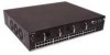
... contains descriptions for the following: • DXS-3250 Front Panel • DXS-3227 Front Panel • Back Panels DXS-3250 Front Panel The D-Link DXS-3250 is a 24 port Gigabit Ethernet Managed Switch. There are stackable Gigabit Ethernet Managed Switches. DXS-3227 Front Panel The D-Link DXS-3227 is a 48 port Gigabit Ethernet Managed Switch. The RJ-45 ports are the...
... contains descriptions for the following: • DXS-3250 Front Panel • DXS-3227 Front Panel • Back Panels DXS-3250 Front Panel The D-Link DXS-3250 is a 24 port Gigabit Ethernet Managed Switch. There are stackable Gigabit Ethernet Managed Switches. DXS-3227 Front Panel The D-Link DXS-3227 is a 48 port Gigabit Ethernet Managed Switch. The RJ-45 ports are the...
Installation Guide
Page 12
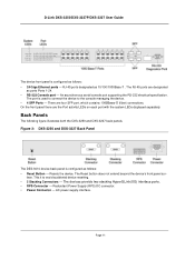
Figure 3: DXS-3250 and DXS-3227 Back Panel The DES-3010 device back panel is used to connect the device to avoid accidental device resetting. • 2 Stacking Connectors - The devices provide two stacking HyperG.Link(XG) interface ports. • RPS Connector - face. AC power supply ...LEDs displayed separately. RJ-45 ports designated as ports Ports 1-24. • RS-232 Console port - Resets the device. D-Link DXS-3250/DXS-3227P/DXS-3227 User Guide The device front panel is configured as follows: • Reset Button - An asynchronous serial console port supporting the...
Figure 3: DXS-3250 and DXS-3227 Back Panel The DES-3010 device back panel is used to connect the device to avoid accidental device resetting. • 2 Stacking Connectors - The devices provide two stacking HyperG.Link(XG) interface ports. • RPS Connector - face. AC power supply ...LEDs displayed separately. RJ-45 ports designated as ports Ports 1-24. • RS-232 Console port - Resets the device. D-Link DXS-3250/DXS-3227P/DXS-3227 User Guide The device front panel is configured as follows: • Reset Button - An asynchronous serial console port supporting the...
Installation Guide
Page 13
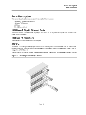
... the Device Page 12 SFP Port Small Form Factor Pluggable (SFP) Optical Transceivers are integrated duplex data GBIC links for bi-directional communication over multimode optical fiber, designed for high-speed Fiber Channel data links. The SFP (GBIC) port can be removed and inserted as 1000Base-X. and full-duplex mode 10/100...
... the Device Page 12 SFP Port Small Form Factor Pluggable (SFP) Optical Transceivers are integrated duplex data GBIC links for bi-directional communication over multimode optical fiber, designed for high-speed Fiber Channel data links. The SFP (GBIC) port can be removed and inserted as 1000Base-X. and full-duplex mode 10/100...

Installation Guide
Page 14
D-Link DXS-3250/DXS-3227P/DXS-3227 User Guide Stacking Ports The device provides two stacking HyperG.Link interface ports. This interface configuration is as follows: • Eight data bits. • One stop bit. • No parity. • Baud rate is an asynchronous ...
D-Link DXS-3250/DXS-3227P/DXS-3227 User Guide Stacking Ports The device provides two stacking HyperG.Link interface ports. This interface configuration is as follows: • Eight data bits. • One stop bit. • No parity. • Baud rate is an asynchronous ...
Installation Guide
Page 16
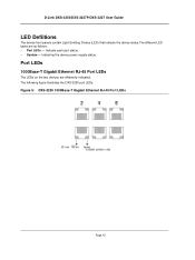
The following figure illustrates the DXS-3250 port LEDs. Figure 5: DXS-3250 1000Base-T Gigabit Ethernet RJ-45 Port LEDs Page 15 Port LEDs 1000Base-T Gigabit Ethernet RJ-45 Port LEDs The LEDs on the two devices are as follows: • Port LEDs - D-Link DXS-3250/DXS-3227P/DXS-3227 User Guide LED Defiitions The device front panels contain Light Emitting Diodes (LED) that indicate the device status.The different LED types are differently indicated. Indicating the device power supply status. Indicate each port status. • System -
The following figure illustrates the DXS-3250 port LEDs. Figure 5: DXS-3250 1000Base-T Gigabit Ethernet RJ-45 Port LEDs Page 15 Port LEDs 1000Base-T Gigabit Ethernet RJ-45 Port LEDs The LEDs on the two devices are as follows: • Port LEDs - D-Link DXS-3250/DXS-3227P/DXS-3227 User Guide LED Defiitions The device front panels contain Light Emitting Diodes (LED) that indicate the device status.The different LED types are differently indicated. Indicating the device power supply status. Indicate each port status. • System -

Installation Guide
Page 17
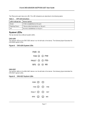
...following figure illustrates the port LEDs. A 10-Mbps link is data transmission on the port. There is established on the port. Figure 7: SFP LEDs Page 16 A 100-Mbps link is established on the port. A link is established on the port. No link is established on the port. The following table: ... LED LED Indication Green Amber Off Green Flashing Green Off Description A 1000-Mbps link is established on the port. SFP LEDs The following figure illustrates the port LEDs. Figure 6: DXS-3227 1000Base-T Gigabit Ethernet RJ-45 Port LEDs The RJ-45 ports on the left side of ...
...following figure illustrates the port LEDs. A 10-Mbps link is data transmission on the port. There is established on the port. Figure 7: SFP LEDs Page 16 A 100-Mbps link is established on the port. A link is established on the port. No link is established on the port. The following table: ... LED LED Indication Green Amber Off Green Flashing Green Off Description A 1000-Mbps link is established on the port. SFP LEDs The following figure illustrates the port LEDs. Figure 6: DXS-3227 1000Base-T Gigabit Ethernet RJ-45 Port LEDs The RJ-45 ports on the left side of ...
Installation Guide
Page 18
... of the device. System LEDs The two devices have one LED. No link is established on the port. The following figure illustrates the DXS-3227 system LEDs. DXS-3250 The sytstem LEDs on the DXS-3250 device in the following table: Table 3: SFP LED Indications LED Indication... Green Flashing Green Off Description A link is data transmission on the left side of the device. The LED indications are described in on the port. There is established on the port. D-Link DXS-3250/DXS-3227P/DXS-3227 User Guide The Fiber ports each have different system ...
... of the device. System LEDs The two devices have one LED. No link is established on the port. The following figure illustrates the DXS-3227 system LEDs. DXS-3250 The sytstem LEDs on the DXS-3250 device in the following table: Table 3: SFP LED Indications LED Indication... Green Flashing Green Off Description A link is data transmission on the left side of the device. The LED indications are described in on the port. There is established on the port. D-Link DXS-3250/DXS-3227P/DXS-3227 User Guide The Fiber ports each have different system ...
Installation Guide
Page 19
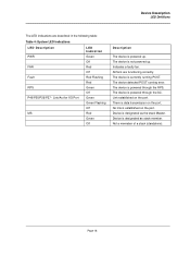
... running POST. Device Description LED Defiitions The LED indications are functioning correctly. The device is data transmission on the port. There is currently running error. Link/Act for XG Port MS LED Indication Green Off Red Off Red Flashing Red Green Off Green Green Flashing Off Red Green Off Description The... powered up . Device is not powered up . The device is designated as the stack Master. Indicates a faulty fan. The device is established on the port. Link established on the port. No link is powered through the AC. Page 18
... running POST. Device Description LED Defiitions The LED indications are functioning correctly. The device is data transmission on the port. There is currently running error. Link/Act for XG Port MS LED Indication Green Off Red Off Red Flashing Red Green Off Green Green Flashing Off Red Green Off Description The... powered up . Device is not powered up . The device is designated as the stack Master. Indicates a faulty fan. The device is established on the port. Link established on the port. No link is powered through the AC. Page 18
Installation Guide
Page 20
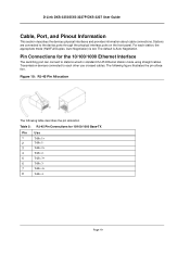
Figure 10: RJ-45 Pin Allocation The following figure illustrates the pin allocation. For each other use crossed cables. D-Link DXS-3250/DXS-3227P/DXS-3227 User Guide Cable, Port, and Pinout Information This section describes the devices physical interfaces and provides information about cable connections. The default is set.... mode using straight cables. The following table describes the pin allocation Table 5: RJ-45 Pin Connections for the 10/100/1000 Ethernet Interface The switching port can connect to the device ports through the physical interface ports on the front panel.
Figure 10: RJ-45 Pin Allocation The following figure illustrates the pin allocation. For each other use crossed cables. D-Link DXS-3250/DXS-3227P/DXS-3227 User Guide Cable, Port, and Pinout Information This section describes the devices physical interfaces and provides information about cable connections. The default is set.... mode using straight cables. The following table describes the pin allocation Table 5: RJ-45 Pin Connections for the 10/100/1000 Ethernet Interface The switching port can connect to the device ports through the physical interface ports on the front panel.

Installation Guide
Page 22
Mounting Device This section contains information for installing the device, and includes the following sections: • Preparing for Installation • Installing the Device • Connecting the Device • Rack Installation Page 21 D-Link DXS-3250/DXS-3227P/DXS-3227 User Guide Section 2.
Mounting Device This section contains information for installing the device, and includes the following sections: • Preparing for Installation • Installing the Device • Connecting the Device • Rack Installation Page 21 D-Link DXS-3250/DXS-3227P/DXS-3227 User Guide Section 2.

Installation Guide
Page 24
...; Rack kit • An AC power cable • Console RS-232 cable with the device. 2. It is found missing or damaged, please contact your local D-Link reseller for damage. Carefully remove the device from the container and place it on an ESD wrist strap and attach the ESD clip to a metal... following : 1. Place the container on a clean flat surface and cut all packing material. 6. Report any item is recommended to put on a secure and clean surface. 5. D-Link DXS-3250/DXS-3227P/DXS-3227 User Guide • Ambient Requirements -
...; Rack kit • An AC power cable • Console RS-232 cable with the device. 2. It is found missing or damaged, please contact your local D-Link reseller for damage. Carefully remove the device from the container and place it on an ESD wrist strap and attach the ESD clip to a metal... following : 1. Place the container on a clean flat surface and cut all packing material. 6. Report any item is recommended to put on a secure and clean surface. 5. D-Link DXS-3250/DXS-3227P/DXS-3227 User Guide • Ambient Requirements -
Installation Guide
Page 26
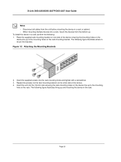
D-Link DXS-3250/DXS-3227P/DXS-3227 User Guide Notes • Disconnect all cables from the unit before mounting the device in the rack. Figure 12: Attaching the Mounting Brackets 2. The ...
D-Link DXS-3250/DXS-3227P/DXS-3227 User Guide Notes • Disconnect all cables from the unit before mounting the device in the rack. Figure 12: Attaching the Mounting Brackets 2. The ...
Installation Guide
Page 28
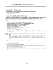
... you have Windows 2000 Service Pack 2 or later installed. D-Link DXS-3250/DXS-3227P/DXS-3227 User Guide Connecting the Device This section describes how to connect the device, and includes the following sections: • Connecting the Switch to a Terminal • AC Power Connection Connecting the Switch to a Terminal The device is green. Connect the power...
... you have Windows 2000 Service Pack 2 or later installed. D-Link DXS-3250/DXS-3227P/DXS-3227 User Guide Connecting the Device This section describes how to connect the device, and includes the following sections: • Connecting the Switch to a Terminal • AC Power Connection Connecting the Switch to a Terminal The device is green. Connect the power...


