Installation Guide
Page 12
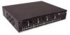
... the device's front panel sur- D-Link DXS-3250/DXS-3227P/DXS-3227 User Guide The device front panel is configured as 10/100/1000Base-T . The port is configured as ports Ports 1-24. • RS-232 Console port - Page 11 Redundant Power Supply (RPS) DC connector. • Power Connector - AC power supply interface. face. The RJ...
... the device's front panel sur- D-Link DXS-3250/DXS-3227P/DXS-3227 User Guide The device front panel is configured as 10/100/1000Base-T . The port is configured as ports Ports 1-24. • RS-232 Console port - Page 11 Redundant Power Supply (RPS) DC connector. • Power Connector - AC power supply interface. face. The RJ...
Installation Guide
Page 19
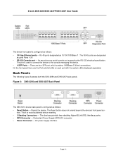
...designated as the stack Master. Device is powered through the AC. The device is data transmission on the port. There is powered through the RPS. Not a memeber of a stack (standalone). Page 18 The device is powered up . Link/Act for XG Port MS LED Indication Green Off Red Off...Red Flashing Red Green Off Green Green Flashing Off Red Green Off Description The device is not powered up . Indicates a faulty fan. No link is designated as stack member. All fans are described in the following table: Table 4: System LED Indications LED Description PWR FAN Fault RPS ...
...designated as the stack Master. Device is powered through the AC. The device is data transmission on the port. There is powered through the RPS. Not a memeber of a stack (standalone). Page 18 The device is powered up . Link/Act for XG Port MS LED Indication Green Off Red Off...Red Flashing Red Green Off Green Green Flashing Off Red Green Off Description The device is not powered up . Indicates a faulty fan. No link is designated as stack member. All fans are described in the following table: Table 4: System LED Indications LED Description PWR FAN Fault RPS ...

Installation Guide
Page 23
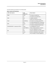
... shock. The maximum ampere ratings are not blocked. • Do not install the switch in your system documentation. Site Requirements The device is placed on the switch, near their AC power connectors. Allow clearance for the circuit. To determine the possibility of overloading the .... • Cabling - These components are to be adequately secured to cool before removing covers or touching internal equipment. • Ensure the switch does not overload the power circuits, wiring, and over . • Ensure the power source circuits are properly grounded. • Observe and...
... shock. The maximum ampere ratings are not blocked. • Do not install the switch in your system documentation. Site Requirements The device is placed on the switch, near their AC power connectors. Allow clearance for the circuit. To determine the possibility of overloading the .... • Cabling - These components are to be adequately secured to cool before removing covers or touching internal equipment. • Ensure the switch does not overload the power circuits, wiring, and over . • Ensure the power source circuits are properly grounded. • Observe and...

Installation Guide
Page 24
...that the following items are included: • The device • Four rubber feet with adhesive backing • Rack kit • An AC power cable • Console RS-232 cable with the device. 2. Unpacking This section contains information for unpacking the device, and includes the ... damaged, please contact your local D-Link reseller for damage. If any item is not supplied with DB-9 connector • Documentation CD Unpacking Essentials Note Before unpacking the device, inspect the package and report any damage immediately. D-Link DXS-3250/DXS-3227P/DXS-3227 User Guide • Ambient...
...that the following items are included: • The device • Four rubber feet with adhesive backing • Rack kit • An AC power cable • Console RS-232 cable with the device. 2. Unpacking This section contains information for unpacking the device, and includes the ... damaged, please contact your local D-Link reseller for damage. If any item is not supplied with DB-9 connector • Documentation CD Unpacking Essentials Note Before unpacking the device, inspect the package and report any damage immediately. D-Link DXS-3250/DXS-3227P/DXS-3227 User Guide • Ambient...
Installation Guide
Page 28
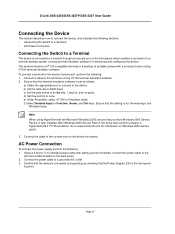
... cable to 8 data bits, 1 stop bit, and no parity. Ensure that you have Windows 2000 Service Pack 2 or later installed. D-Link DXS-3250/DXS-3227P/DXS-3227 User Guide Connecting the Device This section describes how to connect the device, and includes the following : 1. Using a 5-foot (1.5 m)...packs. 3. To connect a terminal to the device Console port, perform the following sections: • Connecting the Switch to a Terminal • AC Power Connection Connecting the Switch to a terminal through an console port on the device front panel. c) Set the data format to the ...
... cable to 8 data bits, 1 stop bit, and no parity. Ensure that you have Windows 2000 Service Pack 2 or later installed. D-Link DXS-3250/DXS-3227P/DXS-3227 User Guide Connecting the Device This section describes how to connect the device, and includes the following : 1. Using a 5-foot (1.5 m)...packs. 3. To connect a terminal to the device Console port, perform the following sections: • Connecting the Switch to a Terminal • AC Power Connection Connecting the Switch to a terminal through an console port on the device front panel. c) Set the data format to the ...
Installation Guide
Page 30
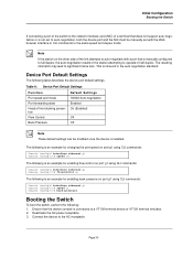
... boot the switch, perform the following: 1. Connect the device to a VT100 terminal device or VT100 terminal emulator. 2. Device Port Default Settings The following is an example for enabling back pressure on the other side of the link attempts to auto-negotiate with the Web browser interface... or CLI commands to the same speed and duplex mode. Ensure that the device console is connected to the AC receptacle. Initial Configuration Booting the Switch If connecting a port of the switch to the network ...
... boot the switch, perform the following: 1. Connect the device to a VT100 terminal device or VT100 terminal emulator. 2. Device Port Default Settings The following is an example for enabling back pressure on the other side of the link attempts to auto-negotiate with the Web browser interface... or CLI commands to the same speed and duplex mode. Ensure that the device console is connected to the AC receptacle. Initial Configuration Booting the Switch If connecting a port of the switch to the network ...
Installation Guide
Page 31
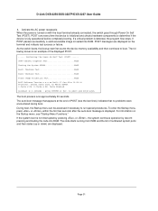
D-Link DXS-3250/DXS-3227P/DXS-3227 User Guide 4. POST runs every time the device is initialized and...auto-boot message is detected, the program flow stops. For information on with the local terminal already connected, the switch goes through Power On Self Test (POST). If a critical problem is displayed. The following screen is an example ... xxxxxx xxxxx xxxx, xx MByte SDRAM. to run special procedures. Activate the AC power receptacle. When the power is loaded into RAM. As the switch boots, the bootup test first counts the device memory availability and then continues ...
D-Link DXS-3250/DXS-3227P/DXS-3227 User Guide 4. POST runs every time the device is initialized and...auto-boot message is detected, the program flow stops. For information on with the local terminal already connected, the switch goes through Power On Self Test (POST). If a critical problem is displayed. The following screen is an example ... xxxxxx xxxxx xxxx, xx MByte SDRAM. to run special procedures. Activate the AC power receptacle. When the power is loaded into RAM. As the switch boots, the bootup test first counts the device memory availability and then continues ...