Product Manual
Page 2
... to the Switch...4 Login Web-based Management Utility ...5 Smart Wizard ...5 Web-based Management Utility...5 SmartConsole Utility...5 Product Introduction ...7 DGS-1216T ...7 Front Panel ...7 Rear Panel...8 DGS-1224T ...8 Front Panel ...8 Rear Panel...9 DGS-1224TP...9 Front Panel ...9 Rear Panel...10 DGS-1248T ...10 Front... device 17 Device List...18 Configuration ...19 Smart Wizard Configuration...19 Password Settings...19 i Table of Contents D-Link Web Smart Switch User Manual Table of Contents Table of Contents ...i About This Guide...1 Online Resources...1 Terms/Usage...1 Copy Right...
... to the Switch...4 Login Web-based Management Utility ...5 Smart Wizard ...5 Web-based Management Utility...5 SmartConsole Utility...5 Product Introduction ...7 DGS-1216T ...7 Front Panel ...7 Rear Panel...8 DGS-1224T ...8 Front Panel ...8 Rear Panel...9 DGS-1224TP...9 Front Panel ...9 Rear Panel...10 DGS-1248T ...10 Front... device 17 Device List...18 Configuration ...19 Smart Wizard Configuration...19 Password Settings...19 i Table of Contents D-Link Web Smart Switch User Manual Table of Contents Table of Contents ...i About This Guide...1 Online Resources...1 Terms/Usage...1 Copy Right...
Product Manual
Page 3
Table of Contents D-Link Web Smart Switch User Manual SNMP Settings ...20 System Settings...21 Identifying the Web-based Management Utility 22 Tool Menu ...22 Reset ...22 ...Emission (EMI) Certifications ...3 Safety Certifications...3 Features ...3 L2 Features ...3 VLAN ...3 ii Ethernet Technology...1 Gigabit Ethernet Technology ...1 Fast Ethernet Technology...1 Switching Technology ...1 Power over Ethernet (PoE) > PoE System Settings (Only for DGS-1224TP 36 QoS > 802.1p/DSCP Priority Settings...37 Security > Trusted Host...38 Security > Safeguard Engine...39 Security > Broadcast Storm...
Table of Contents D-Link Web Smart Switch User Manual SNMP Settings ...20 System Settings...21 Identifying the Web-based Management Utility 22 Tool Menu ...22 Reset ...22 ...Emission (EMI) Certifications ...3 Safety Certifications...3 Features ...3 L2 Features ...3 VLAN ...3 ii Ethernet Technology...1 Gigabit Ethernet Technology ...1 Fast Ethernet Technology...1 Switching Technology ...1 Power over Ethernet (PoE) > PoE System Settings (Only for DGS-1224TP 36 QoS > 802.1p/DSCP Priority Settings...37 Security > Trusted Host...38 Security > Safeguard Engine...39 Security > Broadcast Storm...
Product Manual
Page 11
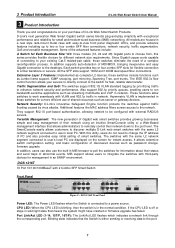
... address filters screen access to be configured with external RADIUS servers. If the CPU LED is in network. 3 Product Introduction D-Link Web Smart Switch User Manual 3 Product Introduction Thank you and congratulations on the screen for different network size requirements. They support 802.1X port... upgrade has failed. Also support 802.1p priority queues, enabling users to a power source. DGS-1216T Front Panel Power LED: The Power LED flashes when the Switch is connected to run bandwidth-sensitive applications such as server or gateway devices. Since Gigabit copper ...
... address filters screen access to be configured with external RADIUS servers. If the CPU LED is in network. 3 Product Introduction D-Link Web Smart Switch User Manual 3 Product Introduction Thank you and congratulations on the screen for different network size requirements. They support 802.1X port... upgrade has failed. Also support 802.1p priority queues, enabling users to a power source. DGS-1216T Front Panel Power LED: The Power LED flashes when the Switch is connected to run bandwidth-sensitive applications such as server or gateway devices. Since Gigabit copper ...
Product Manual
Page 12
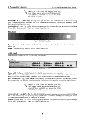
...15T and 16T. Blinking state indicates that means the system might have crashed or firmware upgrade has failed. 3 Product Introduction D-Link Web Smart Switch User Manual NOTE: On DGS-1216T, the MiniGBIC ports 15F and 16F are shared with normal RJ-45 ports 23T and 24T. Rear Panel Figure 9 -... orange light denotes a valid 10 or 100Mbps link on 1000Mbps. NOTE: On DGS-1224T, the MiniGBIC ports 23F and 24F are shared with 2 Combo SFP Smart Switch Front Panel Figure 10 - DGS-1224T Front Panel Power LED: The Power LED flashes when the Switch is in the normal condition. CPU LED: When...
...15T and 16T. Blinking state indicates that means the system might have crashed or firmware upgrade has failed. 3 Product Introduction D-Link Web Smart Switch User Manual NOTE: On DGS-1216T, the MiniGBIC ports 15F and 16F are shared with normal RJ-45 ports 23T and 24T. Rear Panel Figure 9 -... orange light denotes a valid 10 or 100Mbps link on 1000Mbps. NOTE: On DGS-1224T, the MiniGBIC ports 23F and 24F are shared with 2 Combo SFP Smart Switch Front Panel Figure 10 - DGS-1224T Front Panel Power LED: The Power LED flashes when the Switch is in the normal condition. CPU LED: When...
Product Manual
Page 13
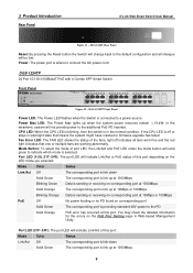
...the LED mode you selected: Mode Color Status Link/Act Off The corresponding port is link down Solid Green The corresponding port is where to a power source. If the CPU LED is selected. DGS-1224T Rear Panel Reset: By pressing the Reset button the Switch will change back to indicate which mode is ...off indicates all changes will indicate Link/Act or PoE status of the fans, light off or stays in the...
...the LED mode you selected: Mode Color Status Link/Act Off The corresponding port is link down Solid Green The corresponding port is where to a power source. If the CPU LED is selected. DGS-1224T Rear Panel Reset: By pressing the Reset button the Switch will change back to indicate which mode is ...off indicates all changes will indicate Link/Act or PoE status of the fans, light off or stays in the...
Product Manual
Page 14
... Panel Power: The power port is connected to a power source. DGS-1248T 48 Port 10/100/1000BaseT with normal RJ-45 ports 45T to connect the AC power cord. DGS-1248T Front Panel Power LED: The Power LED flashes when the Switch is where to 48T. When MiniGBIC port is in the normal condition..., then the switch is used, the RJ-45 port cannot be used . NOTE: On DGS-1248T, the MiniGBIC ports 45F to 48F are shared with normal RJ-45 ports 21T to the default configuration and all changes will be lost . 10 A steady orange light denotes a valid 10 or 100Mbps link on the port...
... Panel Power: The power port is connected to a power source. DGS-1248T 48 Port 10/100/1000BaseT with normal RJ-45 ports 45T to connect the AC power cord. DGS-1248T Front Panel Power LED: The Power LED flashes when the Switch is where to 48T. When MiniGBIC port is in the normal condition..., then the switch is used, the RJ-45 port cannot be used . NOTE: On DGS-1248T, the MiniGBIC ports 45F to 48F are shared with normal RJ-45 ports 21T to the default configuration and all changes will be lost . 10 A steady orange light denotes a valid 10 or 100Mbps link on the port...

Product Manual
Page 15
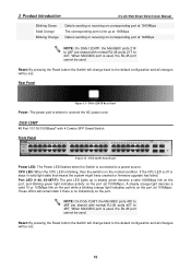
DGS-1248T Rear Panel Power: The power port is where to connect the AC power cord. 11 3 Product Introduction Rear Panel D-Link Web Smart Switch User Manual Figure 15 -
DGS-1248T Rear Panel Power: The power port is where to connect the AC power cord. 11 3 Product Introduction Rear Panel D-Link Web Smart Switch User Manual Figure 15 -
Product Manual
Page 39
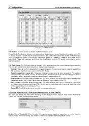
... RJ-45 port is the power usage information of the port. Click "all" to remove all ports into port mirroring. 5 Configuration D-Link Web Smart Switch User Manual Selection options for DGS-1224TP) DGS-1224TP supports Power over Ethernet (PoE) as follows: TX (transmit) mode: Duplicates the data transmitted from the source port and forwards...
... RJ-45 port is the power usage information of the port. Click "all" to remove all ports into port mirroring. 5 Configuration D-Link Web Smart Switch User Manual Selection options for DGS-1224TP) DGS-1224TP supports Power over Ethernet (PoE) as follows: TX (transmit) mode: Duplicates the data transmitted from the source port and forwards...
Product Manual
Page 40
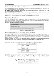
Select from "Class 1", "Class 2", "Class 3" and "Auto" for DGS-1224TP) This page will negotiate and follow the classification from the PD power current based on ...the cable diagnostic function to the PD. Power over the maximum power limitation defined on corresponding port. To protect the DGS-1224TP and the connected devices, the power limit function will disable the PoE function of PD suddenly require more than the...(Only for the power limit. PoE > PoE Port Setting PoE Enable: Select to the Management Station. 36 5 Configuration D-Link Web Smart Switch User Manual Figure 62 -
Select from "Class 1", "Class 2", "Class 3" and "Auto" for DGS-1224TP) This page will negotiate and follow the classification from the PD power current based on ...the cable diagnostic function to the PD. Power over the maximum power limitation defined on corresponding port. To protect the DGS-1224TP and the connected devices, the power limit function will disable the PoE function of PD suddenly require more than the...(Only for the power limit. PoE > PoE Port Setting PoE Enable: Select to the Management Station. 36 5 Configuration D-Link Web Smart Switch User Manual Figure 62 -
Product Manual
Page 50
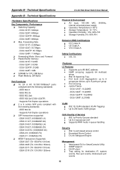
...-310GT (1000BASE-LX) - DEM-330R (TX-1310/RX-1550nm) - Appendix B - IEEE 802.3 - DEM-211 (100BASE-FX) WDM Transceivers Supported: - DGS-1248T: 96Gbps Max. DGS-1224T: 512KB - Technical Specifications D-Link Web Smart Switch User Manual Appendix B - DGS-1248T: 71.4Mpps Forwarding Mode: Store and Forward Packet Buffer memory: - IEEE 802.3u - DEM-311GT (1000BASE-SX) - DEM-210 (100BASE...
...-310GT (1000BASE-LX) - DEM-330R (TX-1310/RX-1550nm) - Appendix B - IEEE 802.3 - DEM-211 (100BASE-FX) WDM Transceivers Supported: - DGS-1248T: 96Gbps Max. DGS-1224T: 512KB - Technical Specifications D-Link Web Smart Switch User Manual Appendix B - DGS-1248T: 71.4Mpps Forwarding Mode: Store and Forward Packet Buffer memory: - IEEE 802.3u - DEM-311GT (1000BASE-SX) - DEM-210 (100BASE...


