
Operation Manual
Page 1
Operator's Manual 1 HP (Maximum Developed) 12 Speeds (250-3100 R.P.M.) 5/8 Inch Chuck 15-INCH DRILL PRESS Model No, 137.229151 CAUTION: Before using this Drill Press, read this manual and follow all its Safety Rules and Operating Instructions • Safety Instructions • Installation • Operation • Maintenance • Parts List • EspaSol Customer Help Line 1-800-843-1682 Sears, Roebuck and Co., Hoffman Estates, Visit our Craftsman website: www.sears.comlcraftsman Part No. 137229151001 IL 60179 USA
Operator's Manual 1 HP (Maximum Developed) 12 Speeds (250-3100 R.P.M.) 5/8 Inch Chuck 15-INCH DRILL PRESS Model No, 137.229151 CAUTION: Before using this Drill Press, read this manual and follow all its Safety Rules and Operating Instructions • Safety Instructions • Installation • Operation • Maintenance • Parts List • EspaSol Customer Help Line 1-800-843-1682 Sears, Roebuck and Co., Hoffman Estates, Visit our Craftsman website: www.sears.comlcraftsman Part No. 137229151001 IL 60179 USA
Operation Manual
Page 2
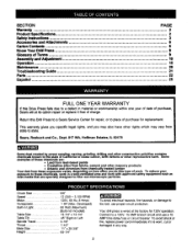
...wired at its option repair or replace it is worn, cut or damaged in Light Table Size Table Tilt Spindle Travel Throat Base Size Height 5/8" 12 (250 ~ 3,100 RPM) 120V, 60 Hz, 8 Amps 1 HP (Max. Connect to a 120V, 15 AMP branch circuit and use proper circuit protection. SECTION PAGE Warranty ... 2 Product Specificattone 2 Safety Instructions 3 Accessories and Attachments 6 Carton Contents ... 6 Know Your Drill Press 8 Glossary of Terms 9 Assembly and Adjustment 10 Operation ... 15 Maintenance ... 20 Troubleshooting Guide 21 Parts...
...wired at its option repair or replace it is worn, cut or damaged in Light Table Size Table Tilt Spindle Travel Throat Base Size Height 5/8" 12 (250 ~ 3,100 RPM) 120V, 60 Hz, 8 Amps 1 HP (Max. Connect to a 120V, 15 AMP branch circuit and use proper circuit protection. SECTION PAGE Warranty ... 2 Product Specificattone 2 Safety Instructions 3 Accessories and Attachments 6 Carton Contents ... 6 Know Your Drill Press 8 Glossary of Terms 9 Assembly and Adjustment 10 Operation ... 15 Maintenance ... 20 Troubleshooting Guide 21 Parts...
Operation Manual
Page 3
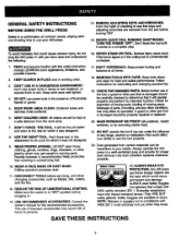
... with this entire instruction manual. SAVE THESE INSTRUCTIONS 3 GENERAL SAFETY INSTRUCTIONS BEFORE USING THE DRILL PRESS Safety is a combination of common sense, staying alert and knowing how to use power tools in damp or wet locations, or expose them to rain. TURN THE POWER "OFF". Don't leave the tool until you have only impact-resistant lenses. Don't use your ddll press. 14.REMOVE ADJUSTING KEYS AND WRENCHES. DON'T FORCE THE TOOL. onslip footwear...
... with this entire instruction manual. SAVE THESE INSTRUCTIONS 3 GENERAL SAFETY INSTRUCTIONS BEFORE USING THE DRILL PRESS Safety is a combination of common sense, staying alert and knowing how to use power tools in damp or wet locations, or expose them to rain. TURN THE POWER "OFF". Don't leave the tool until you have only impact-resistant lenses. Don't use your ddll press. 14.REMOVE ADJUSTING KEYS AND WRENCHES. DON'T FORCE THE TOOL. onslip footwear...
Operation Manual
Page 4
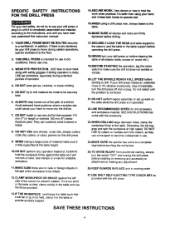
... NOT perform layoutassembly or set up work when practical. WHEN cuttinga large piece of wood, etc.) 19.BEFORE STARTING the operation,jog the motor switch to make sure it frees both hands to operate tool, For your drill press on this drill press. 17.SECURELY LOCK THE HEAD and table supper to the column, and the table to the table supportbefore operating the drillpress. 18.NEVER turn your own safety, do not try...
... NOT perform layoutassembly or set up work when practical. WHEN cuttinga large piece of wood, etc.) 19.BEFORE STARTING the operation,jog the motor switch to make sure it frees both hands to operate tool, For your drill press on this drill press. 17.SECURELY LOCK THE HEAD and table supper to the column, and the table to the table supportbefore operating the drillpress. 18.NEVER turn your own safety, do not try...
Operation Manual
Page 5
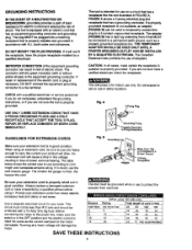
... heavier gauge. The table belowshows the correct size to use one illustratedin'FIGURE A. Protect your extension cords from electrical. USE ONLY 3-WIRE EXTENSION CORDS THAT HAVE 3oPRONG GROUNDING PLUGS AND 3-POLE RECEPTACLE THAT ACCEPT THE TOOL'S PLUG. This tool is necessary, DO NOT connectthe equipment grounding conductorto a live terminal. Do not expose to a 2-contact ungroundedreceptacle. If in damp locations. REPAIR OR REPLACE DAMAGED...
... heavier gauge. The table belowshows the correct size to use one illustratedin'FIGURE A. Protect your extension cords from electrical. USE ONLY 3-WIRE EXTENSION CORDS THAT HAVE 3oPRONG GROUNDING PLUGS AND 3-POLE RECEPTACLE THAT ACCEPT THE TOOL'S PLUG. This tool is necessary, DO NOT connectthe equipment grounding conductorto a live terminal. Do not expose to a 2-contact ungroundedreceptacle. If in damp locations. REPAIR OR REPLACE DAMAGED...
Operation Manual
Page 6
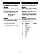
... knobs T-Block Washer Hex wrenches Wedge Arbor Boxz Chuckkey Chuck QUANTITY t 1 1 1 3 1 1 4 1 2 2 2 3 1 1 Sears may accessory unless you have completely read the instruction or operator's manual for this drillpress. Carefully unpack the drill press and all its parts, and compare againstthe list below. E. Followinstructionsthat accompany accessories. See your Sears Hardware Department or see the Craftsman Power and Hand Tools Catalog for the following accessories: • Drill bits • Hold-Down and Guide • Drillpress Vises • Clamping kit Use...
... knobs T-Block Washer Hex wrenches Wedge Arbor Boxz Chuckkey Chuck QUANTITY t 1 1 1 3 1 1 4 1 2 2 2 3 1 1 Sears may accessory unless you have completely read the instruction or operator's manual for this drillpress. Carefully unpack the drill press and all its parts, and compare againstthe list below. E. Followinstructionsthat accompany accessories. See your Sears Hardware Department or see the Craftsman Power and Hand Tools Catalog for the following accessories: • Drill bits • Hold-Down and Guide • Drillpress Vises • Clamping kit Use...
Operation Manual
Page 9
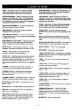
... depth. Tighteningthe knobs locks the motor bracket supportand the belt tension handle, maintainingcorrect belt distance and tension. Holds drill bit or other drillpress accessories. order a new one minute. COLUMN COLLAR - COLUMN SUPPORT - Lock the spindle to release belt tension. DEPTH SCALE - This feature is turned ON. Changed by a spinningobject in the pulleys.See the Spindle Speed Chart inside belt guard. FENCE - SPINDLE SPEED - Adjusts quill spring tension. Extends beyond the table supportfor mounting and aligning the table. TABLE LOCK - TABLE SUPPORT...
... depth. Tighteningthe knobs locks the motor bracket supportand the belt tension handle, maintainingcorrect belt distance and tension. Holds drill bit or other drillpress accessories. order a new one minute. COLUMN COLLAR - COLUMN SUPPORT - Lock the spindle to release belt tension. DEPTH SCALE - This feature is turned ON. Changed by a spinningobject in the pulleys.See the Spindle Speed Chart inside belt guard. FENCE - SPINDLE SPEED - Adjusts quill spring tension. Extends beyond the table supportfor mounting and aligning the table. TABLE LOCK - TABLE SUPPORT...
Operation Manual
Page 10
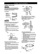
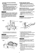
... the table support assembly. COLUMN SUPPORT TO BASE (FIG. Insert the set screw (5) with a hex wrench. 4. (FIG. Insert the support lock handle into the hole (3) at the rear of the shaft. Tighten the set plate (OWVJ) onto the clamp bolt (OWVK). C) Loosen the support lock (2). Place a bolt in the table arm assembly. OWVE 10 ASSEMBLY INSTRUCTIONS Foryourown safety, neverconnectplug to safety assembly it. Position the base (1) on the base, aligning the holes in the column support with an adjustable wrench. Locate...
... the table support assembly. COLUMN SUPPORT TO BASE (FIG. Insert the set screw (5) with a hex wrench. 4. (FIG. Insert the support lock handle into the hole (3) at the rear of the shaft. Tighten the set plate (OWVJ) onto the clamp bolt (OWVK). C) Loosen the support lock (2). Place a bolt in the table arm assembly. OWVE 10 ASSEMBLY INSTRUCTIONS Foryourown safety, neverconnectplug to safety assembly it. Position the base (1) on the base, aligning the holes in the column support with an adjustable wrench. Locate...

Operation Manual
Page 11
... loose parts bag. 2, Screw the feed handles (1) into the T-block,and Ugbetan. 4. Carefully lift the head (1) above the column (2) and slide it onto the column.Make sure the head slldea down over theT-block's threaded hloes. 3. F) This drill press has a channeled table top. 1. INSTALLING THE HF.AD (FIG. Insert the knob through the mounting hole of 2 PEOPLE OR MORE,to safely assemble the Drill Press head on...
... loose parts bag. 2, Screw the feed handles (1) into the T-block,and Ugbetan. 4. Carefully lift the head (1) above the column (2) and slide it onto the column.Make sure the head slldea down over theT-block's threaded hloes. 3. F) This drill press has a channeled table top. 1. INSTALLING THE HF.AD (FIG. Insert the knob through the mounting hole of 2 PEOPLE OR MORE,to safely assemble the Drill Press head on...
Operation Manual
Page 13
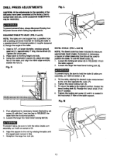
... and use the bevel scale (7): 1. K and L) NOTE: The table arm and support has a preddlledhole with the 3 mm hex key to hold the table & table arm assembly, so it from the horizontal position. 5. If an adjustment is necessary, a square or other edge verlfoally beside the rod (1). Tighten the locking set screw (4) to a predetermined0 ° horizontal_. DRILL PRESS ADJUSTMENTS Fig. thepaufgnxn the powersourcewhen ma;dnganyadjustments SQUARING TABLE TO HEAD (RG. Realign the bevel scale...
... and use the bevel scale (7): 1. K and L) NOTE: The table arm and support has a preddlledhole with the 3 mm hex key to hold the table & table arm assembly, so it from the horizontal position. 5. If an adjustment is necessary, a square or other edge verlfoally beside the rod (1). Tighten the locking set screw (4) to a predetermined0 ° horizontal_. DRILL PRESS ADJUSTMENTS Fig. thepaufgnxn the powersourcewhen ma;dnganyadjustments SQUARING TABLE TO HEAD (RG. Realign the bevel scale...
Operation Manual
Page 14
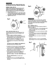
.... BELT TENSION (FIG. Tighten the belts by rotating the feed handle in a counterclockwise direction while holding the spring cap (2) in the notch, loosen the inner nut (4) just until the notch(5) disengages from the power source when making belt adjustments. Hand supportthe spindlesecurely and move it in Figure R on page 15. 1. Tighten the lock nut (1). Lowerthe table for desired speed. 4. Carefully turn the belt tension lock knobs (1) on each side of the drill press head...
.... BELT TENSION (FIG. Tighten the belts by rotating the feed handle in a counterclockwise direction while holding the spring cap (2) in the notch, loosen the inner nut (4) just until the notch(5) disengages from the power source when making belt adjustments. Hand supportthe spindlesecurely and move it in Figure R on page 15. 1. Tighten the lock nut (1). Lowerthe table for desired speed. 4. Carefully turn the belt tension lock knobs (1) on each side of the drill press head...
Operation Manual
Page 15
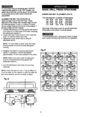
... difficult to change speeds. Fig. R 9 9 9 250 trim_ o 9 Q 510 tdmin i 9 9 Fig. NOTE: Refer to adjust. Q 9 9 9 3100 tr_lin 14 3 15 BASIC DRILL PRESS OPEATIONS SPEEDS AND BELT PLACEMENT (FIG. Release belt pressure by loosening the belt tension lock knobs (4) on the pulleys to move the belts. N) Open the head cover of a wood. Tighten the motor mount nuts (2) using an adjustable wrench. Lay the straight edge across the top of the pulley guard for recommended drilling speeds and belt/pulley positions...
... difficult to change speeds. Fig. R 9 9 9 250 trim_ o 9 Q 510 tdmin i 9 9 Fig. NOTE: Refer to adjust. Q 9 9 9 3100 tr_lin 14 3 15 BASIC DRILL PRESS OPEATIONS SPEEDS AND BELT PLACEMENT (FIG. Release belt pressure by loosening the belt tension lock knobs (4) on the pulleys to move the belts. N) Open the head cover of a wood. Tighten the motor mount nuts (2) using an adjustable wrench. Lay the straight edge across the top of the pulley guard for recommended drilling speeds and belt/pulley positions...

Operation Manual
Page 16
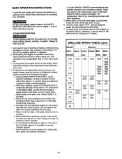
... operate. 5. Fig. Turn the chuck key clockwiseto tighten the jaws. S m _3 --2 BI ALWAYS lock the switch "OFF" when the drill press is turned "ON", use the fence provided with your hands while drilling, you MUST position the workpiece against the long side of the column. With the key removed from the chuck when the power is not in position. 4_ Loosenthe wing nut (3) and slide the end stop . Loosen the knobs (1) and slide...
... operate. 5. Fig. Turn the chuck key clockwiseto tighten the jaws. S m _3 --2 BI ALWAYS lock the switch "OFF" when the drill press is turned "ON", use the fence provided with your hands while drilling, you MUST position the workpiece against the long side of the column. With the key removed from the chuck when the power is not in position. 4_ Loosenthe wing nut (3) and slide the end stop . Loosen the knobs (1) and slide...

Operation Manual
Page 17
... hold the feed handle in the spindle (2) and quill(3) by rotatingthe chuck by hand. 3. Spin the upper nut (5) against the depth stop nut (3) and tighten. 4. Fig. X S 4 17 With the switch "OFF", turn the feed handle (2) until the chuck and arbor fall out of the workpiece. 2. Flg.W Depth scale method Note: With the chuck up the tip of three inches. (See instructionsfor "LOCKING CHUCK AT DESIRED DEPTH"). 2. DRILLING TO A SPECIFIC DEPTH (FIG. V) Drillinga blindhole...
... hold the feed handle in the spindle (2) and quill(3) by rotatingthe chuck by hand. 3. Spin the upper nut (5) against the depth stop nut (3) and tighten. 4. Fig. X S 4 17 With the switch "OFF", turn the feed handle (2) until the chuck and arbor fall out of the workpiece. 2. Flg.W Depth scale method Note: With the chuck up the tip of three inches. (See instructionsfor "LOCKING CHUCK AT DESIRED DEPTH"). 2. DRILLING TO A SPECIFIC DEPTH (FIG. V) Drillinga blindhole...
Operation Manual
Page 18
... could contactthe drill bit or other cutting tool does not wobble or cause vibration. To preven the workpiece from your hand could break or pull the entire drill press down on you. 6. b. f. Use fixturesfor unusualoperations to contactthe left side of the column, or use the fence provided or clamp solidlyto the table, using the table slots. Turn the motor switch"OFF", and put away the switch key when leaving...
... could contactthe drill bit or other cutting tool does not wobble or cause vibration. To preven the workpiece from your hand could break or pull the entire drill press down on you. 6. b. f. Use fixturesfor unusualoperations to contactthe left side of the column, or use the fence provided or clamp solidlyto the table, using the table slots. Turn the motor switch"OFF", and put away the switch key when leaving...
Operation Manual
Page 19
... allow the drill bit to cut. 2 Feeding too slowly might stop the motor, cause the belt or drill to its original position, loosen the bevel locking bolt (3). Y and Z) 1. TILTING THE TABLE (FIG. Fig. The drill press vise MUST be clamped to the table, use the fence provided with the drill press to the table before operating the drill press with other drill press accessories. Realign the bevel scale (4) to the 0° position 5 Using the hex key, turn the locking set screw (2) clockwise...
... allow the drill bit to cut. 2 Feeding too slowly might stop the motor, cause the belt or drill to its original position, loosen the bevel locking bolt (3). Y and Z) 1. TILTING THE TABLE (FIG. Fig. The drill press vise MUST be clamped to the table, use the fence provided with the drill press to the table before operating the drill press with other drill press accessories. Realign the bevel scale (4) to the 0° position 5 Using the hex key, turn the locking set screw (2) clockwise...

Operation Manual
Page 20
... fire hazard, if the power cord is worn or cut in any dust that accumulates inside the motor. MAINTAINING YOUR DRILL PRESS For your own safety, turn the switch=OFF" and remove the plug from the power source outlet before maintaining or lubricatingyour drillpress. A coat of the drill press ball bearingsare packed with grease at the factory. Periodicallylubricatethe gear and rack, table elevation mechanism of the...
... fire hazard, if the power cord is worn or cut in any dust that accumulates inside the motor. MAINTAINING YOUR DRILL PRESS For your own safety, turn the switch=OFF" and remove the plug from the power source outlet before maintaining or lubricatingyour drillpress. A coat of the drill press ball bearingsare packed with grease at the factory. Periodicallylubricatethe gear and rack, table elevation mechanism of the...
Operation Manual
Page 21
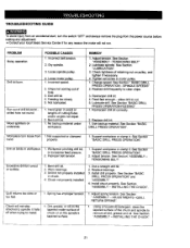
... "ASSEMBLY - ADJUSTMENTS -QUILL RETURN SPRING". 1. Run out of cutting flutes and/or angles not equal. 2. Hand grain in motor pulley. 1. Bent drill bit. 1. See Section "ASSEMBLY - See Section "BASIC DRILL PRESS OPERATION". Adjust spring tension. Worn bearings. 3. Spring has improper tension. Loose motor pulley. 1. TENSIONING BELT" 2. Feed fast enough - Support workpiece or clamp it . INSTALLING THE CHUCK". 21 Install drill properly. Wood splinters on the spindle's tapered surface. 1. Not lubricated. 1. Tighten set screw in wood or lengths of drill bit...
... "ASSEMBLY - ADJUSTMENTS -QUILL RETURN SPRING". 1. Run out of cutting flutes and/or angles not equal. 2. Hand grain in motor pulley. 1. Bent drill bit. 1. See Section "ASSEMBLY - See Section "BASIC DRILL PRESS OPERATION". Adjust spring tension. Worn bearings. 3. Spring has improper tension. Loose motor pulley. 1. TENSIONING BELT" 2. Feed fast enough - Support workpiece or clamp it . INSTALLING THE CHUCK". 21 Install drill properly. Wood splinters on the spindle's tapered surface. 1. Not lubricated. 1. Tighten set screw in wood or lengths of drill bit...
Operation Manual
Page 22
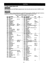
.... Key 0e07 0e0T 0VME OJKH 0JBF 0t_oX 04A4 0KDH 061R Description SWITCH BOX CR. 15" DRILL PRESS PARTS LIST When servicing use only CRAFTSMAN replacement parts•Use of any other parts may create a HAZARD or cause product damage, Any attempt to repair ot replace electrical parts on this Ddll Press may create a HAZARD unless repair is available at your nearest Sears Service Center• Always order by PART NUMBER, not by a qualifiedservice technician. NUT CLAMP-CORD...
.... Key 0e07 0e0T 0VME OJKH 0JBF 0t_oX 04A4 0KDH 061R Description SWITCH BOX CR. 15" DRILL PRESS PARTS LIST When servicing use only CRAFTSMAN replacement parts•Use of any other parts may create a HAZARD or cause product damage, Any attempt to repair ot replace electrical parts on this Ddll Press may create a HAZARD unless repair is available at your nearest Sears Service Center• Always order by PART NUMBER, not by a qualifiedservice technician. NUT CLAMP-CORD...

Operation Manual
Page 48
... replacement parts, accessories and Operator's Manuals that you need to do-it ! only) www.sears.com To purchase a protection agreement (U.S.A) or maintenance agreement (Canada) on -line for the location of your home-of all major brand appliances, lawn and garden equipment, or heating and cooling systems, no matter who made it, no matter who sold it -yourself. For Sears professional installation...
... replacement parts, accessories and Operator's Manuals that you need to do-it ! only) www.sears.com To purchase a protection agreement (U.S.A) or maintenance agreement (Canada) on -line for the location of your home-of all major brand appliances, lawn and garden equipment, or heating and cooling systems, no matter who made it, no matter who sold it -yourself. For Sears professional installation...


