Operation Manual
Page 1
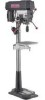
Operator's Manual 1 HP (Maximum Developed) 12 Speeds (250-3100 R.P.M.) 5/8 Inch Chuck 15-INCH DRILL PRESS Model No, 137.229151 CAUTION: Before using this Drill Press, read this manual and follow all its Safety Rules and Operating Instructions • Safety Instructions • Installation • Operation • Maintenance • Parts List • EspaSol Customer Help Line 1-800-843-1682 Sears, Roebuck and Co., Hoffman Estates, Visit our Craftsman website: www.sears.comlcraftsman Part No. 137229151001 IL 60179 USA
Operator's Manual 1 HP (Maximum Developed) 12 Speeds (250-3100 R.P.M.) 5/8 Inch Chuck 15-INCH DRILL PRESS Model No, 137.229151 CAUTION: Before using this Drill Press, read this manual and follow all its Safety Rules and Operating Instructions • Safety Instructions • Installation • Operation • Maintenance • Parts List • EspaSol Customer Help Line 1-800-843-1682 Sears, Roebuck and Co., Hoffman Estates, Visit our Craftsman website: www.sears.comlcraftsman Part No. 137229151001 IL 60179 USA
Operation Manual
Page 2
... PAGE Warranty ... 2 Product Specificattone 2 Safety Instructions 3 Accessories and Attachments 6 Carton Contents ... 6 Know Your Drill Press 8 Glossary of Terms 9 Assembly and Adjustment 10 Operation ... 15 Maintenance ... 20 Troubleshooting Guide 21 Parts ... 22 Espafiol 25 FULL ONE YEAR WARRANTY If this Driss Press fails due to a defect in material or workmanship within one year of date of...
... PAGE Warranty ... 2 Product Specificattone 2 Safety Instructions 3 Accessories and Attachments 6 Carton Contents ... 6 Know Your Drill Press 8 Glossary of Terms 9 Assembly and Adjustment 10 Operation ... 15 Maintenance ... 20 Troubleshooting Guide 21 Parts ... 22 Espafiol 25 FULL ONE YEAR WARRANTY If this Driss Press fails due to a defect in material or workmanship within one year of date of...
Operation Manual
Page 3
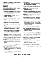
..., a guard or other pert that is damaged should be carefully checked to determine that it comes to a complete stop. Always operate the drill press in . 13. DISCONNECTTOOLS before plugging in a well-ventilated area and provide for the recommended accessories. ALWAYS wear Safety Goggles (not glasses) ... until it will operate property and perform its operation.A guard or other part that could cause sedous injury, do the job better and safer at a safe distance from the tool before turning =ON". 15. Check for best and safest performance. MAKE WORKSHOP laD PROOF with ANSI...
..., a guard or other pert that is damaged should be carefully checked to determine that it comes to a complete stop. Always operate the drill press in . 13. DISCONNECTTOOLS before plugging in a well-ventilated area and provide for the recommended accessories. ALWAYS wear Safety Goggles (not glasses) ... until it will operate property and perform its operation.A guard or other part that could cause sedous injury, do the job better and safer at a safe distance from the tool before turning =ON". 15. Check for best and safest performance. MAKE WORKSHOP laD PROOF with ANSI...
Operation Manual
Page 4
...part of a drill bit. Otherwise, the bit may grap and spin the workpiece at high speed. Use clamps or a vise for drill accessory and workpiece material. ALWAYS keep hands out of the path of the workpiece to a complete stop immediately, turn the switch"OFF" and unplug the drill press before drilling....with the drill press 13.IF THE WORKPIECE overhangs the table such that exceeds 175 mm (7") in workingorder. 27.USE ONLY SELF-EJECTING TYPE CHUCK KEY as they can suddenly bend outward or break. 8. Do not restart until you have read and understoodthis instrucbonmanual: 15.WHEN ...
...part of a drill bit. Otherwise, the bit may grap and spin the workpiece at high speed. Use clamps or a vise for drill accessory and workpiece material. ALWAYS keep hands out of the path of the workpiece to a complete stop immediately, turn the switch"OFF" and unplug the drill press before drilling....with the drill press 13.IF THE WORKPIECE overhangs the table such that exceeds 175 mm (7") in workingorder. 27.USE ONLY SELF-EJECTING TYPE CHUCK KEY as they can suddenly bend outward or break. 8. Do not restart until you have read and understoodthis instrucbonmanual: 15.WHEN ...
Operation Manual
Page 6
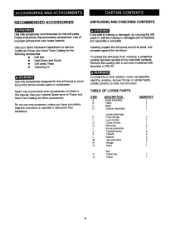
...drill press and all its parts, and compare againstthe list below. TABLE OF LOOSE PARTS ITEM A. B. C. H. N. Q. F. I. P. Sears may accessory unless you have completely read the instruction or operator's manual for this manual. See your Sears Hardware Department or see the Craftsman Power and Hand Tools Catalog for the following accessories: • Drill... for other accessories not listed in untilthe missingor damaged part is replaced, and assembly is missingor damaged, do not plug the drill press in this drill press to the machined surfaces. Do not use gasoline, ...
...drill press and all its parts, and compare againstthe list below. TABLE OF LOOSE PARTS ITEM A. B. C. H. N. Q. F. I. P. Sears may accessory unless you have completely read the instruction or operator's manual for this manual. See your Sears Hardware Department or see the Craftsman Power and Hand Tools Catalog for the following accessories: • Drill... for other accessories not listed in untilthe missingor damaged part is replaced, and assembly is missingor damaged, do not plug the drill press in this drill press to the machined surfaces. Do not use gasoline, ...
Operation Manual
Page 10
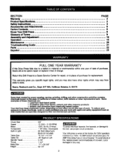
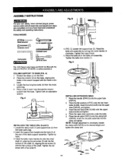
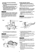
... upper tube (OWVH), and tighten. 3. i INSTALLING THE TABLE (FIG. Locate the table crank (1) and support lock (2) from the loose parts bag. 4. NOTE: If length adjustment is very heavy and MUST be liftedwith the helpof 2 PEOPLE OR MORE, to power sourceoutletuntilall assemblyand adjustmentsteps ...are completed, and you have read and understood the safetyand operatinginstructions. Locate the four long hex bolts (3) from the loose parts bag. 2. Insert the bolt (OJUB) into the table and tighten. Insert the support lock handle into the hole (3) at the ...
... upper tube (OWVH), and tighten. 3. i INSTALLING THE TABLE (FIG. Locate the table crank (1) and support lock (2) from the loose parts bag. 4. NOTE: If length adjustment is very heavy and MUST be liftedwith the helpof 2 PEOPLE OR MORE, to power sourceoutletuntilall assemblyand adjustmentsteps ...are completed, and you have read and understood the safetyand operatinginstructions. Locate the four long hex bolts (3) from the loose parts bag. 2. Insert the bolt (OJUB) into the table and tighten. Insert the support lock handle into the hole (3) at the ...

Operation Manual
Page 11
...11 Align the mounting holes of the fence into the threaded holes (2) in the loose parts bag. 2, Screw the feed handles (1) into the T-block,and Ugbetan. 4. FENCE ASSEMBLY (FIG. D) mvl/_d_ql K_ The Drill Press h_d Is very heavy and MUST be lifted with the base. 2. Carefully lift the ... over theT-block's threaded hloes. 3. Insert the knob through the mounting hole of the fence over the column as far as shown 2. F) This drill press has a channeled table top. 1. Fig. F J"ry _3 INSTALLING FEES HANDLES (FIG. Repeat for the fence (1).Sllde theT-blocks (2) Into the ...
...11 Align the mounting holes of the fence into the threaded holes (2) in the loose parts bag. 2, Screw the feed handles (1) into the T-block,and Ugbetan. 4. FENCE ASSEMBLY (FIG. D) mvl/_d_ql K_ The Drill Press h_d Is very heavy and MUST be lifted with the base. 2. Carefully lift the ... over theT-block's threaded hloes. 3. Insert the knob through the mounting hole of the fence over the column as far as shown 2. F) This drill press has a channeled table top. 1. Fig. F J"ry _3 INSTALLING FEES HANDLES (FIG. Repeat for the fence (1).Sllde theT-blocks (2) Into the ...

Operation Manual
Page 16
... cannot be turned "OFF" but not far enough to secure the workpiece could result in use only the self-ejecting chuck key supplied with the drill press to the "ON" position 2. Turn the lightswitch and power switch"OFF" and wait until it can be restartedwithout insertingthe switch key. 6. In...open the chuck jaws (1) using the chuck key (2). Remove the key and keep it in the =OFF" position, grasp the end, or yellow part, of the workpiece firmly to prevent it comesto a complete stop. Fig.T To preventthe workpiece or backup materialfrom being tom from the chuck when the ...
... cannot be turned "OFF" but not far enough to secure the workpiece could result in use only the self-ejecting chuck key supplied with the drill press to the "ON" position 2. Turn the lightswitch and power switch"OFF" and wait until it can be restartedwithout insertingthe switch key. 6. In...open the chuck jaws (1) using the chuck key (2). Remove the key and keep it in the =OFF" position, grasp the end, or yellow part, of the workpiece firmly to prevent it comesto a complete stop. Fig.T To preventthe workpiece or backup materialfrom being tom from the chuck when the ...
Operation Manual
Page 18
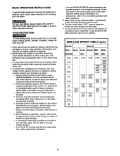
... wear looseclothing,gloves, neckties, or jewelry. b. c. f. h. Never climbon the drill press table, it to the table. Never place your drill press is missing, malfunctioning, damaged or broken, stop operation immediately until that part is tilted, use the fence providedand a clamp to brace a small workpiece. ...chart belowfor drillingspeed information.For accessories, refer to the table arm, before operating the drill press. To avoid injuryfrom thrownwork or tool contact,do any part of the column. BASIC OPERATION INSTRUCTIONS To get the best results and minimize the ...
... wear looseclothing,gloves, neckties, or jewelry. b. c. f. h. Never climbon the drill press table, it to the table. Never place your drill press is missing, malfunctioning, damaged or broken, stop operation immediately until that part is tilted, use the fence providedand a clamp to brace a small workpiece. ...chart belowfor drillingspeed information.For accessories, refer to the table arm, before operating the drill press. To avoid injuryfrom thrownwork or tool contact,do any part of the column. BASIC OPERATION INSTRUCTIONS To get the best results and minimize the ...
Operation Manual
Page 19
...to release it against the LEFT side of the drillbit (3) is not long enough to reach the column, use the fence provided with other drill press accessories. Lock the table (1) to brace the workpiece. Using a centerpunchor sharp nail, make an indentationin the workpiece where you MUST position ...vise or bit parts. If the workpiece or the backup matedal is just above the top of the column. Using the feed handles,bdng the drilldownto align with a locking set screw (2) clockwise to slip, or tear the workpiece loose and break the drill bit 3. To use a drill press vise (optinal ...
...to release it against the LEFT side of the drillbit (3) is not long enough to reach the column, use the fence provided with other drill press accessories. Lock the table (1) to brace the workpiece. Using a centerpunchor sharp nail, make an indentationin the workpiece where you MUST position ...vise or bit parts. If the workpiece or the backup matedal is just above the top of the column. Using the feed handles,bdng the drilldownto align with a locking set screw (2) clockwise to slip, or tear the workpiece loose and break the drill bit 3. To use a drill press vise (optinal ...
Operation Manual
Page 22
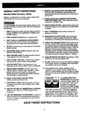
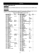
... HANDLE BAR ABS'Y SCALE RING BPR_NGCAP 05YI SPRING RETA_NEB OKPV HF.X. 15" DRILL PRESS PARTS LIST When servicing use only CRAFTSMAN replacement parts•Use of any other parts may create a HAZARD or cause product damage, Any attempt to repair ot replace electrical parts on this Ddll Press may create a HAZARD unless repair is available at your nearest Sears...
... HANDLE BAR ABS'Y SCALE RING BPR_NGCAP 05YI SPRING RETA_NEB OKPV HF.X. 15" DRILL PRESS PARTS LIST When servicing use only CRAFTSMAN replacement parts•Use of any other parts may create a HAZARD or cause product damage, Any attempt to repair ot replace electrical parts on this Ddll Press may create a HAZARD unless repair is available at your nearest Sears...

Operation Manual
Page 48
For the replacement parts, accessories and Operator's Manuals that you need to do-it ! For Sears professional installation of home appliances and items like vacuums, lawn equipment, and electronics, ...) www.sears.com To purchase a protection agreement (U.S.A) or maintenance agreement (Canada) on -line for the location of your home-of carry-in your nearest Sears Parts & Repair Center. 1-800-488-1222 Call anytime,dayor night(U.S.A.
For the replacement parts, accessories and Operator's Manuals that you need to do-it ! For Sears professional installation of home appliances and items like vacuums, lawn equipment, and electronics, ...) www.sears.com To purchase a protection agreement (U.S.A) or maintenance agreement (Canada) on -line for the location of your home-of carry-in your nearest Sears Parts & Repair Center. 1-800-488-1222 Call anytime,dayor night(U.S.A.

