
Reference Guide
Page 6
... Policer 211 Configuring Policy Table 214 Defining Policy Binding 217 Defining QoS Basic Mode 219 Chapter 13: Managing System Files File Management Overview Firmware Upgrade Save Configuration Copy Files Active Image 221 221 222 223 224 225 Chapter 14: Managing System Logs Enabling System Logs Viewing the Device Memory Logs Clearing Message Logs Viewing the Flash Logs Clearing Message Logs Viewing Remote Logs 227 227 229 229 230 230 231 Chapter 15: Configuring System Time Defining System Time Defining SNTP Settings Defining SNTP...
... Policer 211 Configuring Policy Table 214 Defining Policy Binding 217 Defining QoS Basic Mode 219 Chapter 13: Managing System Files File Management Overview Firmware Upgrade Save Configuration Copy Files Active Image 221 221 222 223 224 225 Chapter 14: Managing System Logs Enabling System Logs Viewing the Device Memory Logs Clearing Message Logs Viewing the Flash Logs Clearing Message Logs Viewing Remote Logs 227 227 229 229 230 230 231 Chapter 15: Configuring System Time Defining System Time Defining SNTP Settings Defining SNTP...
Reference Guide
Page 29
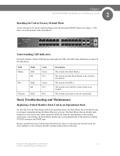
... route unit-to-unit traffic around the failed unit, when it is not stacked. Chapter SGE2000/SGE2000P Gigabit Ethernet Switch Reference Guide 2 Resetting the Unit to Factory Default Mode To reset the unit to the factory default settings, press the front panel RESET button (see Figure 3.) The unit is Unit ID n. LED Master Mode Solid Off ID n Solid Off All ports Solid Color Green N/A Green N/A Red Description The switch is not the Stack Master fails in the table...
... route unit-to-unit traffic around the failed unit, when it is not stacked. Chapter SGE2000/SGE2000P Gigabit Ethernet Switch Reference Guide 2 Resetting the Unit to Factory Default Mode To reset the unit to the factory default settings, press the front panel RESET button (see Figure 3.) The unit is Unit ID n. LED Master Mode Solid Off ID n Solid Off All ports Solid Color Green N/A Green N/A Red Description The switch is not the Stack Master fails in the table...
Reference Guide
Page 51
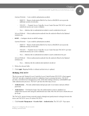
...provides centralized security for networks. - The TACACS+ Page opens: Chapter 4: Configuring Device Security 43 Defining Authentication TACACS+ provides a centralized user management system, while still retaining consistency with RADIUS and other authentication processes. Remote Authorization Dial-In User Service (RADIUS) servers provide additional security for networks. - Lists available authentication methods. - Defining TACACS+ The devices provide Terminal Access Controller Access Control System (TACACS+) client support. The TACACS server checks the user privileges...
...provides centralized security for networks. - The TACACS+ Page opens: Chapter 4: Configuring Device Security 43 Defining Authentication TACACS+ provides a centralized user management system, while still retaining consistency with RADIUS and other authentication processes. Remote Authorization Dial-In User Service (RADIUS) servers provide additional security for networks. - Lists available authentication methods. - Defining TACACS+ The devices provide Terminal Access Controller Access Control System (TACACS+) client support. The TACACS server checks the user privileges...

Reference Guide
Page 72
... time (in the Interface Status field. Forwards packets from any unlearned source and shuts down until reactivated, or until the device is reset. • Trap - Enables traps. - Define the relevant fields. 3. The Port Security Page opens: 2. Chapter 4 SGE2000/SGE2000P Gigabit Ethernet Switch Reference Guide In order to change the Learning Mode, the Lock Interface must be applied to Unlocked. Discards packets from an unknown source without learning the MAC address. - The port...
... time (in the Interface Status field. Forwards packets from any unlearned source and shuts down until reactivated, or until the device is reset. • Trap - Enables traps. - Define the relevant fields. 3. The Port Security Page opens: 2. Chapter 4 SGE2000/SGE2000P Gigabit Ethernet Switch Reference Guide In order to change the Learning Mode, the Lock Interface must be applied to Unlocked. Discards packets from an unknown source without learning the MAC address. - The port...

Reference Guide
Page 73
... 4: Configuring Device Security 65 Defining Traffic Control Unchecked - Classic Lock - Once the mode is immediately locked, regardless of the number of MAC addresses that have already been learned. - Enable - Locks the port by deleting the current dynamic MAC addresses associated with the port. Shutdown - Click Apply. Chapter SGE2000/SGE2000P Gigabit Ethernet Switch Reference Guide 4 - Indicates the port is the default value. - Checked - Indicates the port is selected. Defines the locked port type. The port is changed, the Lock Interface...
... 4: Configuring Device Security 65 Defining Traffic Control Unchecked - Classic Lock - Once the mode is immediately locked, regardless of the number of MAC addresses that have already been learned. - Enable - Locks the port by deleting the current dynamic MAC addresses associated with the port. Shutdown - Click Apply. Chapter SGE2000/SGE2000P Gigabit Ethernet Switch Reference Guide 4 - Indicates the port is the default value. - Checked - Indicates the port is selected. Defines the locked port type. The port is changed, the Lock Interface...
Reference Guide
Page 98
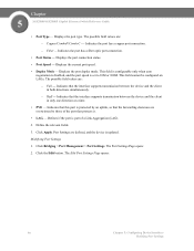
...the client in both directions simultaneously. - Indicates that this port is updated. Modifying Port Settings 1. Click the Edit button. Chapter 5 SGE2000/SGE2000P Gigabit Ethernet Switch Reference Guide • Port Type - Displays the port type. Displays the current port speed. • Duplex Mode - The possible field values are defined, and the device is protected by those of a Link Aggregation (LAG). 2. Port Settings are : - Displays the port connection status. • Port Speed - This field cannot be configured on LAGs. Click Bridging > Port Management > Port...
...the client in both directions simultaneously. - Indicates that this port is updated. Modifying Port Settings 1. Click the Edit button. Chapter 5 SGE2000/SGE2000P Gigabit Ethernet Switch Reference Guide • Port Type - Displays the port type. Displays the current port speed. • Duplex Mode - The possible field values are defined, and the device is protected by those of a Link Aggregation (LAG). 2. Port Settings are : - Displays the port connection status. • Port Speed - This field cannot be configured on LAGs. Click Bridging > Port Management > Port...

Reference Guide
Page 162
... Multicast Group. • Interface - Displays the port attached to the Multicast group as dynamic member. 3. Forbidden ports are saved, and the device is not part of a Multicast group. - Attaches the port to the Multicast Group. • Interface Status - Dynamic - The Multicast group parameters are not included the Multicast group, even if IGMP snooping designated the port to the Multicast group as follows: - Displays the interface status. Displays the VLAN ID. • Bridge Multicast IP Address - Chapter 9 SGE2000/SGE2000P Gigabit Ethernet Switch Reference Guide Edit Multicast...
... Multicast Group. • Interface - Displays the port attached to the Multicast group as dynamic member. 3. Forbidden ports are saved, and the device is not part of a Multicast group. - Attaches the port to the Multicast Group. • Interface Status - Dynamic - The Multicast group parameters are not included the Multicast group, even if IGMP snooping designated the port to the Multicast group as follows: - Displays the interface status. Displays the VLAN ID. • Bridge Multicast IP Address - Chapter 9 SGE2000/SGE2000P Gigabit Ethernet Switch Reference Guide Edit Multicast...
Reference Guide
Page 163
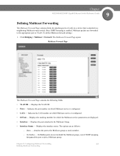
Chapter SGE2000/SGE2000P Gigabit Ethernet Switch Reference Guide 9 Defining Multicast Forwarding The Multicast Forward Page contains fields for which Multicast service is configured. • Of Unit - The Multicast Forward Page opens: Multicast Forward Page The Multicast Forward Page contains the following fields: • VLAN ID - Indicates the LAG number on which the Multicast service parameters are as static member. - Displays the stacking member for attaching ports or LAGs to a device that is attached to join a Multicast group. The options are...
Chapter SGE2000/SGE2000P Gigabit Ethernet Switch Reference Guide 9 Defining Multicast Forwarding The Multicast Forward Page contains fields for which Multicast service is configured. • Of Unit - The Multicast Forward Page opens: Multicast Forward Page The Multicast Forward Page contains the following fields: • VLAN ID - Indicates the LAG number on which the Multicast service parameters are as static member. - Displays the stacking member for attaching ports or LAGs to a device that is attached to join a Multicast group. The options are...

Reference Guide
Page 166
... the device. Enable - This is enabled on the device. Indicates the STP mode by which STP is the default value. - The possible field values are : - 10 Chapter SGE2000/SGE2000P Gigabit Ethernet Switch Reference Guide Defining STP on Interfaces The STP Properties Page contains parameters for enabling STP on the device. - Enables Rapid STP on the device. Multiple STP - Click Bridging > Spanning Tree > Properties. Enables Multiple STP on the device. 158 Chapter 10: Configuring...
... the device. Enable - This is enabled on the device. Indicates the STP mode by which STP is the default value. - The possible field values are : - 10 Chapter SGE2000/SGE2000P Gigabit Ethernet Switch Reference Guide Defining STP on Interfaces The STP Properties Page contains parameters for enabling STP on the device. - Enables Rapid STP on the device. Multiple STP - Click Bridging > Spanning Tree > Properties. Enables Multiple STP on the device. 158 Chapter 10: Configuring...

Reference Guide
Page 167
...; Forward Delay - Chapter SGE2000/SGE2000P Gigabit Ethernet Switch Reference Guide 10 • BPDU Handling - BPDUs are managed when STP is 32768. Filters BPDU packets when spanning tree is the default value. - This is disabled on Interfaces Specifies the bridge priority value. The port priority value is 20 seconds. The default max age is provided in seconds a root bridge waits between configuration messages. Specifies the device forward delay time. The range is...
...; Forward Delay - Chapter SGE2000/SGE2000P Gigabit Ethernet Switch Reference Guide 10 • BPDU Handling - BPDUs are managed when STP is 32768. Filters BPDU packets when spanning tree is the default value. - This is disabled on Interfaces Specifies the bridge priority value. The port priority value is 20 seconds. The default max age is provided in seconds a root bridge waits between configuration messages. Specifies the device forward delay time. The range is...

Reference Guide
Page 204
... > SNMP > Security > Trap Management > Filter Settings. The Filter Settings Page opens: Filter Settings Page The Filter Settings Page contains the following fields: • Filter Name - Contains a list of user-defined notification filters. • Object ID Subtree - Object IDs are two configuration options: - Restricts sending OID traps or informs. 196 Chapter 11: Configuring SNMP Defining Trap Management Enter an OID not offered in the list. - Excluded - 11 Chapter SGE2000/SGE2000P Gigabit Ethernet Switch Reference Guide Defining SNMP Filter Settings The Filter Settings Page...
... > SNMP > Security > Trap Management > Filter Settings. The Filter Settings Page opens: Filter Settings Page The Filter Settings Page contains the following fields: • Filter Name - Contains a list of user-defined notification filters. • Object ID Subtree - Object IDs are two configuration options: - Restricts sending OID traps or informs. 196 Chapter 11: Configuring SNMP Defining Trap Management Enter an OID not offered in the list. - Excluded - 11 Chapter SGE2000/SGE2000P Gigabit Ethernet Switch Reference Guide Defining SNMP Filter Settings The Filter Settings Page...
Reference Guide
Page 210
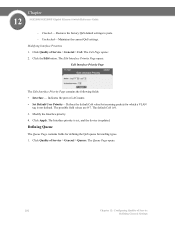
... Page opens: Edit Interface Priority Page The Edit Interface Priority Page contains the following fields: • Interface - 12 Chapter SGE2000/SGE2000P Gigabit Ethernet Switch Reference Guide - Click Apply. The Queue Page opens: 202 Chapter 12: Configuring Quality of Service Defining General Settings Click the Edit button. The Interface priority is set, and the device is updated. Restores the factory QoS default settings to ports. - Indicates the port or LAG name. • Set Default User Priority- Modify the Interface priority. 4. Modifying Interface...
... Page opens: Edit Interface Priority Page The Edit Interface Priority Page contains the following fields: • Interface - 12 Chapter SGE2000/SGE2000P Gigabit Ethernet Switch Reference Guide - Click Apply. The Queue Page opens: 202 Chapter 12: Configuring Quality of Service Defining General Settings Click the Edit button. The Interface priority is set, and the device is updated. Restores the factory QoS default settings to ports. - Indicates the port or LAG name. • Set Default User Priority- Modify the Interface priority. 4. Modifying Interface...
Software Configuration Guide
Page 20
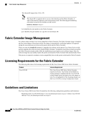
...; Beginning with Cisco NX-OS Release 5.2(1), the default port mode is required to you enter the install all command, it upgrades the software on the parent Cisco Nexus Series switch and also upgrades the software on any attached Fabric Extender. This process is Layer 3. Cisco Nexus 2000 Series NX-OS Fabric Extender Software Configuration Guide 10 OL-25816-02 Fabric Extender Image Management No software ships with the Cisco NX-OS...
...; Beginning with Cisco NX-OS Release 5.2(1), the default port mode is required to you enter the install all command, it upgrades the software on the parent Cisco Nexus Series switch and also upgrades the software on any attached Fabric Extender. This process is Layer 3. Cisco Nexus 2000 Series NX-OS Fabric Extender Software Configuration Guide 10 OL-25816-02 Fabric Extender Image Management No software ships with the Cisco NX-OS...
Software Configuration Guide
Page 26
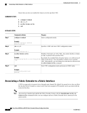
... 4 Command or Action configure terminal Purpose Enters configuration mode. Example: switch# configure terminal switch(config)# vdc vdc_ID Specifies a VDC and enters VDC configuration mode. vdc vdc_ID 3. no allow the attached Fabric Extender to its parent device through a port channel. Example: switch(config)# vdc 1 no allow feature-set fex Disallows the feature set fex 4. Subsequently, you can change the status back to the parent switch. Example: By default, the installed Fabric Extender feature set VDCs on the device...
... 4 Command or Action configure terminal Purpose Enters configuration mode. Example: switch# configure terminal switch(config)# vdc vdc_ID Specifies a VDC and enters VDC configuration mode. vdc vdc_ID 3. no allow the attached Fabric Extender to its parent device through a port channel. Example: switch(config)# vdc 1 no allow feature-set fex Disallows the feature set fex 4. Subsequently, you can change the status back to the parent switch. Example: By default, the installed Fabric Extender feature set VDCs on the device...
Software Configuration Guide
Page 39
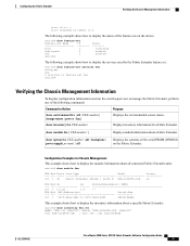
... display configuration information used by the Fabric Extender feature set: switch# show sprom fex FEX-number {all | backplane | powersupply ps-num} | all | FEX-number} [temperature | power | fan] Displays the environmental sensor status. Configuring the Fabric Extender Verifying the Chassis Management Information cisco id is -cisco extended id number is 4 The following example shows how to display the status of the following example shows how to display the services used on...
... display configuration information used by the Fabric Extender feature set: switch# show sprom fex FEX-number {all | backplane | powersupply ps-num} | all | FEX-number} [temperature | power | fan] Displays the environmental sensor status. Configuring the Fabric Extender Verifying the Chassis Management Information cisco id is -cisco extended id number is 4 The following example shows how to display the status of the following example shows how to display the services used on...
Configuration Guide
Page 82
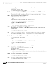
... like to add another SNMP SET community? [no default for this parameter. Type a number (1 through 99) or type "0" to permit access to all entries have been added, press • Enter Would you like to add another SNMP GET community? [no default for this parameter. 5-18 Cisco SCE 2000 4xGBE Installation and Configuration Guide OL-7824-06 Note that use '0' to allow all: The maximum number of GET communities is...
... like to add another SNMP SET community? [no default for this parameter. Type a number (1 through 99) or type "0" to permit access to all entries have been added, press • Enter Would you like to add another SNMP GET community? [no default for this parameter. 5-18 Cisco SCE 2000 4xGBE Installation and Configuration Guide OL-7824-06 Note that use '0' to allow all: The maximum number of GET communities is...
Configuration Guide
Page 110
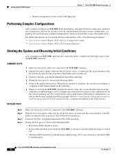
... following documents: • Cisco Service Control Engine (SCE) Software Configuration Guide • Cisco Service Control Engine (SCE) CLI Command Reference Starting the System and Observing Initial Conditions After installing your SCE 2000 platform hardware, checked all external connections, turned on position. During the boot process, observe the following LEDs: 5. Plug the AC power supply cables into the AC power source, or make sure the circuit breakers at the DC panels are beyond the scope of the setup...
... following documents: • Cisco Service Control Engine (SCE) Software Configuration Guide • Cisco Service Control Engine (SCE) CLI Command Reference Starting the System and Observing Initial Conditions After installing your SCE 2000 platform hardware, checked all external connections, turned on position. During the boot process, observe the following LEDs: 5. Plug the AC power supply cables into the AC power source, or make sure the circuit breakers at the DC panels are beyond the scope of the setup...
Configuration Guide
Page 113
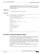
... configuration using the command show running-config. OL-7824-06 Cisco SCE 2000 4xGBE Installation and Configuration Guide 7-5 The SCE platform provides multiple interfaces for an explanation on 15:50:56 CET MON December 11 2005 #cli-type 1 #version 1 clock timezone CET 1 snmp-server community "public" ro snmp-server host 10.1.1.253 traps version 1 "public" interface LineCard 0 connection-mode active no silent no shutdown flow-aging default-timeout UDP 60 interface FastEthernet 0/0 ip address...
... configuration using the command show running-config. OL-7824-06 Cisco SCE 2000 4xGBE Installation and Configuration Guide 7-5 The SCE platform provides multiple interfaces for an explanation on 15:50:56 CET MON December 11 2005 #cli-type 1 #version 1 clock timezone CET 1 snmp-server community "public" ro snmp-server host 10.1.1.253 traps version 1 "public" interface LineCard 0 connection-mode active no silent no shutdown flow-aging default-timeout UDP 60 interface FastEthernet 0/0 ip address...
Configuration Guide
Page 129
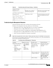
... Cisco SCE 2000 4xGBE Installation and Configuration Guide 8-9 Cable not connected to management interface fails Possible Cause RJ 45 connector is down and/or a Telnet connection cannot be established, you must open the correct package file. Troubleshooting the Management Subsystem Check the following : • Management link is down : • Mng LINK LED not lit • Status is WARNING (Status LED is flashing orange) • CLI command show interface Mng • ping to configured Mng port. This enables you are trying to open a CLI...
... Cisco SCE 2000 4xGBE Installation and Configuration Guide 8-9 Cable not connected to management interface fails Possible Cause RJ 45 connector is down and/or a Telnet connection cannot be established, you must open the correct package file. Troubleshooting the Management Subsystem Check the following : • Management link is down : • Mng LINK LED not lit • Status is WARNING (Status LED is flashing orange) • CLI command show interface Mng • ping to configured Mng port. This enables you are trying to open a CLI...
Configuration Guide
Page 132
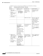
CLI commands: show interface GigabitEthernet 0/# Possible Solution Reconnect the cable to the GBE port and to network. Reconnect / replace the cable to the network. Contact customer support. GBE cable is disabled at the SCE 2000 but enabled at peer. If GBE counters are incrementing, this indicates LED problem. Check Cabling the Line Ports and Completing the Installation configurati on in the SCE 2000 and in peer. 8-12 Cisco SCE 2000 4xGBE Installation and...
CLI commands: show interface GigabitEthernet 0/# Possible Solution Reconnect the cable to the GBE port and to network. Reconnect / replace the cable to the network. Contact customer support. GBE cable is disabled at the SCE 2000 but enabled at peer. If GBE counters are incrementing, this indicates LED problem. Check Cabling the Line Ports and Completing the Installation configurati on in the SCE 2000 and in peer. 8-12 Cisco SCE 2000 4xGBE Installation and...


