
Quick Start Guide
Page 2
... switches support frames up to deploy the device in each packet. 1 Cisco Unmanaged Rackmount Switches Network Speed and Auto MDI/MDI-X Detection All ports support network speed auto-negotiation and auto MDI/MDI-X crossover detection. Auto MDI/MDI-X crossover detection automatically adjusts for communicating with the layout of Service (QoS); Network speed auto-negotiation automatically selects the best connection speed and mode (half- or full-duplex) for the cable type (straight-through or crossover) used to connect...
... switches support frames up to deploy the device in each packet. 1 Cisco Unmanaged Rackmount Switches Network Speed and Auto MDI/MDI-X Detection All ports support network speed auto-negotiation and auto MDI/MDI-X crossover detection. Auto MDI/MDI-X crossover detection automatically adjusts for communicating with the layout of Service (QoS); Network speed auto-negotiation automatically selects the best connection speed and mode (half- or full-duplex) for the cable type (straight-through or crossover) used to connect...
Quick Start Guide
Page 6
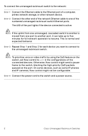
... phones and IP cameras, flow control might send a pause frame to the switch, blocking the high-priority QoS packets queued on the switch, set flow control to off in the configurations of a computer, printer, network storage, or other end of the numbered unmanaged rackmount switch Ethernet ports. To connect the unmanaged rackmount switch to the network: STEP 1 Connect the Ethernet cable to the Ethernet port of the connected devices. The LED of the port lights if the device connected...
... phones and IP cameras, flow control might send a pause frame to the switch, blocking the high-priority QoS packets queued on the switch, set flow control to off in the configurations of a computer, printer, network storage, or other end of the numbered unmanaged rackmount switch Ethernet ports. To connect the unmanaged rackmount switch to the network: STEP 1 Connect the Ethernet cable to the Ethernet port of the connected devices. The LED of the port lights if the device connected...
Quick Start Guide
Page 7
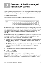
... modules. • MiniGBIC interface is powered on RJ-45 respond to the switch. Link/Act LED-(Green) Lights when a link between the corresponding port and another device is passing traffic. The auto-sensing, Ethernet (802.3) ports are used for your network clients. Each Ethernet port supports network speeds of the unmanaged rackmount switches that provide non-blocking, wire-speed switching for wired network communications. Front Panel LEDs System LED-Lights green when the switch is a combination port, shared with one other switches by using optical fiber. • MiniGBIC ports...
... modules. • MiniGBIC interface is powered on RJ-45 respond to the switch. Link/Act LED-(Green) Lights when a link between the corresponding port and another device is passing traffic. The auto-sensing, Ethernet (802.3) ports are used for your network clients. Each Ethernet port supports network speeds of the unmanaged rackmount switches that provide non-blocking, wire-speed switching for wired network communications. Front Panel LEDs System LED-Lights green when the switch is a combination port, shared with one other switches by using optical fiber. • MiniGBIC ports...
Quick Start Guide
Page 8
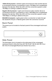
... between the devices. When the LED is off , the connection speed is under 100 Mbps or nothing is cabled to the port. Gigabit LED (if present)-Lights and remains lit when another device is connected to the port, is powered on, and a 100 Mbps link is cabled to the port. POWER Side Panel The Kensington lock is located on the side panel of the unmanaged rackmount switch. Back Panel The power port is...
... between the devices. When the LED is off , the connection speed is under 100 Mbps or nothing is cabled to the port. Gigabit LED (if present)-Lights and remains lit when another device is connected to the port, is powered on, and a 100 Mbps link is cabled to the port. POWER Side Panel The Kensington lock is located on the side panel of the unmanaged rackmount switch. Back Panel The power port is...
Hardware Installation Guide
Page 2
...; and Access Registrar, Aironet, Synods, Bringing the Meeting To You, Catalyst, CCDA, CCDP, CCIE, CCIP, CCNA, CCNP, CCSP, CCVP, Cisco, the Cisco Certified Internetwork Expert logo, Cisco IOS, Cisco Press, Cisco Systems, Cisco Systems Capital, the Cisco Systems logo, Cisco Unity, Collaboration Without Limitation, Enterprise/Solver, Ether Channel, Therapist, Ether Switch, Event Center, Fast Step, Follow Me Browsing, Furnisher, Gig a Drive, Homeland, Internet Quotient, IOS, phone...
...; and Access Registrar, Aironet, Synods, Bringing the Meeting To You, Catalyst, CCDA, CCDP, CCIE, CCIP, CCNA, CCNP, CCSP, CCVP, Cisco, the Cisco Certified Internetwork Expert logo, Cisco IOS, Cisco Press, Cisco Systems, Cisco Systems Capital, the Cisco Systems logo, Cisco Unity, Collaboration Without Limitation, Enterprise/Solver, Ether Channel, Therapist, Ether Switch, Event Center, Fast Step, Follow Me Browsing, Furnisher, Gig a Drive, Homeland, Internet Quotient, IOS, phone...

Hardware Installation Guide
Page 8
... Notes for the Cisco Internet Streamer CDS 2.1 • Cisco Internet Streamer CDS 2.0-2.1 Software Configuration Guide • Cisco Internet Streamer CDS 2.0-2.1 Quick Start Guide • Cisco Internet Streamer CDS 2.0-2.1 API Guide • Cisco Content Delivery System 2.x Documentation Roadmap • Regulatory Compliance and Safety Information for connecting DC power to install a CDE, and provides troubleshooting information. For more information, see the "Related Documentation" section on page viii. Chapter 5, "Hardware Troubleshooting" Presents troubleshooting procedures for...
... Notes for the Cisco Internet Streamer CDS 2.1 • Cisco Internet Streamer CDS 2.0-2.1 Software Configuration Guide • Cisco Internet Streamer CDS 2.0-2.1 Quick Start Guide • Cisco Internet Streamer CDS 2.0-2.1 API Guide • Cisco Content Delivery System 2.x Documentation Roadmap • Regulatory Compliance and Safety Information for connecting DC power to install a CDE, and provides troubleshooting information. For more information, see the "Related Documentation" section on page viii. Chapter 5, "Hardware Troubleshooting" Presents troubleshooting procedures for...
Hardware Installation Guide
Page 17
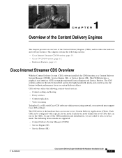
... are supported: • Content Delivery System Manager (CDSM) • Service Engine (SE) • Service Router (SR) OL-13478-03 Cisco Content Delivery Engine 100/200/300/400 Hardware Installation Guide 1-1 The CDSM provides a graphical user interface (GUI) to distribute and receive high-bandwidth, media-rich content across the Internet without performance losses or content delivery delays. The CDE refers to select a device mode. As part of the...
... are supported: • Content Delivery System Manager (CDSM) • Service Engine (SE) • Service Router (SR) OL-13478-03 Cisco Content Delivery Engine 100/200/300/400 Hardware Installation Guide 1-1 The CDSM provides a graphical user interface (GUI) to distribute and receive high-bandwidth, media-rich content across the Internet without performance losses or content delivery delays. The CDE refers to select a device mode. As part of the...

Hardware Installation Guide
Page 18
... CDE100 supports device-mode configuration and can be configured with the CDS 2.0-2.1 software to operate as a CDSM. The OnDemand application is held reliably on the Cisco Content Delivery Engine 100/200/300/400 Hardware Installation Guide 1-2 OL-13478-03 All content is a component of next generation, open architecture vehicle capable of delivering a wide range of one or more CDE200s or CDE400s. The number...
... CDE100 supports device-mode configuration and can be configured with the CDS 2.0-2.1 software to operate as a CDSM. The OnDemand application is held reliably on the Cisco Content Delivery Engine 100/200/300/400 Hardware Installation Guide 1-2 OL-13478-03 All content is a component of next generation, open architecture vehicle capable of delivering a wide range of one or more CDE200s or CDE400s. The number...
Hardware Installation Guide
Page 22
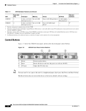
... of storage. Resets the device and runs the power-on a 400-GB drive), including storage of information to support trick play. 4. Cisco Content Delivery Engine 100/200/300/400 Hardware Installation Guide 1-6 OL-13478-03 Normally configured with the CDSM. 2. Control Buttons Figure 1-9 shows the CDE100 front panel, and describes the front panel control buttons. Provides management communication with 12 full-duplex Gigabit Ethernet (GE) interfaces, each used to deliver...
... of storage. Resets the device and runs the power-on a 400-GB drive), including storage of information to support trick play. 4. Cisco Content Delivery Engine 100/200/300/400 Hardware Installation Guide 1-6 OL-13478-03 Normally configured with the CDSM. 2. Control Buttons Figure 1-9 shows the CDE100 front panel, and describes the front panel control buttons. Provides management communication with 12 full-duplex Gigabit Ethernet (GE) interfaces, each used to deliver...
Hardware Installation Guide
Page 27
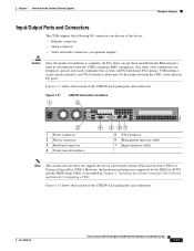
... rear I /O cables, except those installed in Chapter 4, "Installing the Internet Streamer CDS Software and Initially Configuring a CDE." Figure 1-17 1 CDE100 Connector Locations 2 211770 3 1 Power connector 2 Mouse connector 3 Keyboard connector 4 Serial console interface 4 5 67 5 VGA interface 6 Management interface (eth0) 7 Ingest interface (eth1) Note The system software does not support the use of the CDE100 back panel ports and connectors. OL-13478-03 Cisco Content Delivery Engine 100/200/300/400 Hardware Installation Guide 1-11...
... rear I /O cables, except those installed in Chapter 4, "Installing the Internet Streamer CDS Software and Initially Configuring a CDE." Figure 1-17 1 CDE100 Connector Locations 2 211770 3 1 Power connector 2 Mouse connector 3 Keyboard connector 4 Serial console interface 4 5 67 5 VGA interface 6 Management interface (eth0) 7 Ingest interface (eth1) Note The system software does not support the use of the CDE100 back panel ports and connectors. OL-13478-03 Cisco Content Delivery Engine 100/200/300/400 Hardware Installation Guide 1-11...

Hardware Installation Guide
Page 36
... electrical shock. All connections must be removed to a grounded power outlet. The power cable or plug is designed to work with national and local wiring regulations. Cisco Content Delivery Engine 100/200/300/400 Hardware Installation Guide 2-6 OL-13478-03 General Precautions Observe the following conditions occur, unplug the product from the electrical outlet and replace the part or contact your system...
... electrical shock. All connections must be removed to a grounded power outlet. The power cable or plug is designed to work with national and local wiring regulations. Cisco Content Delivery Engine 100/200/300/400 Hardware Installation Guide 2-6 OL-13478-03 General Precautions Observe the following conditions occur, unplug the product from the electrical outlet and replace the part or contact your system...
Hardware Installation Guide
Page 42
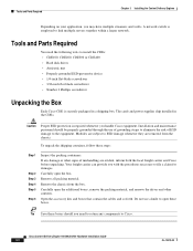
... open the box. Open the accessory kits and boxes that contain the cables and so forth. The cards and power supplies ship installed in a shipping box. To unpack the shipping container, follow these boxes. Caution Proper ESD protection is securely packaged in the CDEs. Remove all packing material. Cisco Content Delivery Engine 100/200/300/400 Hardware Installation Guide 3-2 OL-13478-03 Tools and Parts...
... open the box. Open the accessory kits and boxes that contain the cables and so forth. The cards and power supplies ship installed in a shipping box. To unpack the shipping container, follow these boxes. Caution Proper ESD protection is securely packaged in the CDEs. Remove all packing material. Cisco Content Delivery Engine 100/200/300/400 Hardware Installation Guide 3-2 OL-13478-03 Tools and Parts...

Hardware Installation Guide
Page 44
... device installation starting from the chassis. Preparing the CDEs for the jumper labeled "JPA-1" (located about two inches below the center PCI-X slot-slot 3 of 5). Make sure the 160-GB hard drive is connected to the secondary IDE cable. Replace the top cover on the motherboard. Disable the onboard SCSI controller by connect pins 2 and 3 (instead of 1 and 2) for Rack Installation Verify correct hardware configuration by removing...
... device installation starting from the chassis. Preparing the CDEs for the jumper labeled "JPA-1" (located about two inches below the center PCI-X slot-slot 3 of 5). Make sure the 160-GB hard drive is connected to the secondary IDE cable. Replace the top cover on the motherboard. Disable the onboard SCSI controller by connect pins 2 and 3 (instead of 1 and 2) for Rack Installation Verify correct hardware configuration by removing...

Hardware Installation Guide
Page 45
... all servers. • Mechanical loading-Mount equipment so that a hazardous condition is approved for direct connection to the Telecommunication Network System only through a device that the chassis is complete, all I /O ports. Any other cable connections are temporary and are only used to maintain EMC compliance. OL-13478-03 Cisco Content Delivery Engine 100/200/300/400 Hardware Installation Guide 3-5 Making Physical Connections After mounting the servers, continue the hardware setup...
... all servers. • Mechanical loading-Mount equipment so that a hazardous condition is approved for direct connection to the Telecommunication Network System only through a device that the chassis is complete, all I /O ports. Any other cable connections are temporary and are only used to maintain EMC compliance. OL-13478-03 Cisco Content Delivery Engine 100/200/300/400 Hardware Installation Guide 3-5 Making Physical Connections After mounting the servers, continue the hardware setup...
Hardware Installation Guide
Page 65
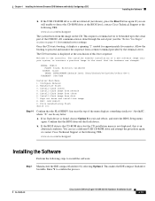
... server to the serial port of a new software image onto your system, or recovers a previous image in the event that the BIOS detected the flash device. The CD boot menu is still not detected (not shown), press the Reset button again. Configure Network 2. Wipe out disks and install.bin image 8. Exit (and reboot) 9. OL-13478-03 Cisco Content Delivery Engine 100/200/300/400 Hardware Installation Guide...
... server to the serial port of a new software image onto your system, or recovers a previous image in the event that the BIOS detected the flash device. The CD boot menu is still not detected (not shown), press the Reset button again. Configure Network 2. Wipe out disks and install.bin image 8. Exit (and reboot) 9. OL-13478-03 Cisco Content Delivery Engine 100/200/300/400 Hardware Installation Guide...
Hardware Installation Guide
Page 67
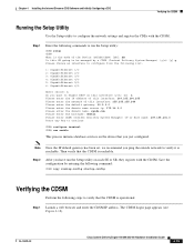
Step 2 After you ping the outside network to verify it is operational: Step 1 Launch a web browser and enter the CDSM IP address. Note Once the IP default gateway has been set, we recommend you have run the Setup utility: CDE# setup CDE# What is reachable. Save the configuration by a CDSM (Content Delivery System Manager) (y/n) [y]:y Please choose an interface to configure from the following list: 1: GigabitEthernet...
Step 2 After you ping the outside network to verify it is operational: Step 1 Launch a web browser and enter the CDSM IP address. Note Once the IP default gateway has been set, we recommend you have run the Setup utility: CDE# setup CDE# What is reachable. Save the configuration by a CDSM (Content Delivery System Manager) (y/n) [y]:y Please choose an interface to configure from the following list: 1: GigabitEthernet...
Hardware Installation Guide
Page 71
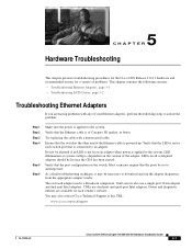
... download and run the adapter diagnostics from the appropriate adapter vendor. The on the version of the adapter. Driver and diagnostic utilities are having problems with a known good cable. LED illumination at this URL: www.cisco.com/techsupport OL-13478-03 Cisco Content Delivery Engine 100/200/300/400 Hardware Installation Guide 5-1 Verify that the Ethernet cable is a Broadcom component. CDEs use a single-port 3Com adapter and dual-port Intel adapters. 5 C H A P T E R Hardware Troubleshooting...
... download and run the adapter diagnostics from the appropriate adapter vendor. The on the version of the adapter. Driver and diagnostic utilities are having problems with a known good cable. LED illumination at this URL: www.cisco.com/techsupport OL-13478-03 Cisco Content Delivery Engine 100/200/300/400 Hardware Installation Guide 5-1 Verify that the Ethernet cable is a Broadcom component. CDEs use a single-port 3Com adapter and dual-port Intel adapters. 5 C H A P T E R Hardware Troubleshooting...

Hardware Installation Guide
Page 72
... the following URL: www.cisco.com/techsupport Cisco Content Delivery Engine 100/200/300/400 Hardware Installation Guide 5-2 OL-13478-03 If the problem still persists, contact Cisco Technical Support at the following steps: Step 1 Step 2 Step 3 Reboot the system. Troubleshooting SATA Drives Chapter 5 Hardware Troubleshooting Troubleshooting SATA Drives The CDE200 and CDE400 contain SATA drives. The SATA controller cards are being reported as the...
... the following URL: www.cisco.com/techsupport Cisco Content Delivery Engine 100/200/300/400 Hardware Installation Guide 5-2 OL-13478-03 If the problem still persists, contact Cisco Technical Support at the following steps: Step 1 Step 2 Step 3 Reboot the system. Troubleshooting SATA Drives Chapter 5 Hardware Troubleshooting Troubleshooting SATA Drives The CDE200 and CDE400 contain SATA drives. The SATA controller cards are being reported as the...

Hardware Installation Guide
Page 103
... 4-1, 4-14 intended uses 2-8 overview 1-1 preparing to install 2-1 registering with CDSM 4-15 safety 2-8 server types 3-1 site requirements 2-1 CDE100 BIOS Setup 4-3 connectors 1-11, 3-6 control buttons 1-6 disk drives 3-9 hardware features 1-5 LEDs 1-8 overview 1-3 physical dimensions 2-2 safety 2-6 safety warnings 2-3 specifications A-2 CDE200 BIOS Setup 4-9 configuring ports 4-2 connecting DC power D-2 connectors 1-12, 3-6 control buttons 1-7 disk drives 3-9 front cover 1-9, 3-11 hardware features 1-5 LEDs 1-9 Cisco Content Delivery Engine 100/200/300/400 Hardware Installation Guide IN-1
... 4-1, 4-14 intended uses 2-8 overview 1-1 preparing to install 2-1 registering with CDSM 4-15 safety 2-8 server types 3-1 site requirements 2-1 CDE100 BIOS Setup 4-3 connectors 1-11, 3-6 control buttons 1-6 disk drives 3-9 hardware features 1-5 LEDs 1-8 overview 1-3 physical dimensions 2-2 safety 2-6 safety warnings 2-3 specifications A-2 CDE200 BIOS Setup 4-9 configuring ports 4-2 connecting DC power D-2 connectors 1-12, 3-6 control buttons 1-7 disk drives 3-9 front cover 1-9, 3-11 hardware features 1-5 LEDs 1-9 Cisco Content Delivery Engine 100/200/300/400 Hardware Installation Guide IN-1

Hardware Installation Guide
Page 106
... 3-5 preparing CDEs for rack 3-4 rack 3-5 rack safety guidelines 3-3 software installation order 4-2 tools and parts 3-2 Integrated Vault Streamer, see ISV interfaces stream 4-2 Internet Streamer CDS overview 1-1 server types 3-1 ISV 3-1 CDE200 ISV 1-2 connections 3-9 L LEDs CDE100 1-8 CDE200 1-9 CDE300 1-10 CDE400 1-10 Lindenhurst chipset 3-1 connector pin assignments B-1 M management interface 1-11 specifications A-4 N network cables 3-8 O overcurrent protection AC circuits 2-9 DC circuits 2-9 IN-4 Cisco Content Delivery Engine 100/200/300/400 Hardware Installation Guide OL-13478-03
... 3-5 preparing CDEs for rack 3-4 rack 3-5 rack safety guidelines 3-3 software installation order 4-2 tools and parts 3-2 Integrated Vault Streamer, see ISV interfaces stream 4-2 Internet Streamer CDS overview 1-1 server types 3-1 ISV 3-1 CDE200 ISV 1-2 connections 3-9 L LEDs CDE100 1-8 CDE200 1-9 CDE300 1-10 CDE400 1-10 Lindenhurst chipset 3-1 connector pin assignments B-1 M management interface 1-11 specifications A-4 N network cables 3-8 O overcurrent protection AC circuits 2-9 DC circuits 2-9 IN-4 Cisco Content Delivery Engine 100/200/300/400 Hardware Installation Guide OL-13478-03


