
Hardware Installation Guide
Page 25
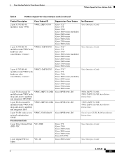
Cisco Interface Cards for Cisco Access Routers Platform Support for Cisco Interface Cards Table 4 Platform Support for Cisco Interface Cards (continued) Product Description 2-port G.703 RJ-48 multiflex trunk VWIC Cisco Product ID VWIC-2MFT-G703 1-port G.703 RJ-48 VWIC2-1MFT-G703 multiflex trunk VWIC with hardware echo cancellation, version 2 2-port G.703 RJ-48 VWIC2-2MFT-G703 multiflex trunk VWIC with hardware echo cancellation, version 2 2-port T1/fractional T1 VWIC-2MFT-T1-DIR multiflex trunk VWIC with drop...
Cisco Interface Cards for Cisco Access Routers Platform Support for Cisco Interface Cards Table 4 Platform Support for Cisco Interface Cards (continued) Product Description 2-port G.703 RJ-48 multiflex trunk VWIC Cisco Product ID VWIC-2MFT-G703 1-port G.703 RJ-48 VWIC2-1MFT-G703 multiflex trunk VWIC with hardware echo cancellation, version 2 2-port G.703 RJ-48 VWIC2-2MFT-G703 multiflex trunk VWIC with hardware echo cancellation, version 2 2-port T1/fractional T1 VWIC-2MFT-T1-DIR multiflex trunk VWIC with drop...
Hardware Installation Guide
Page 31
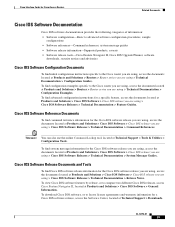
... > Routers > Router series you are using > Technical Documentation > Configuration Examples. Cisco Interface Cards for Cisco Access Routers Related Documents Cisco IOS Software Documentation Cisco IOS software documentation provides the following categories of information: • Software configuration-Basic to advanced software configuration procedures, sample configurations • Software references-Command references, system message guides • Software release information-Supported products, caveats • Software release tools-Cisco Feature Navigator II, Cisco IOS Upgrade...
... > Routers > Router series you are using > Technical Documentation > Configuration Examples. Cisco Interface Cards for Cisco Access Routers Related Documents Cisco IOS Software Documentation Cisco IOS software documentation provides the following categories of information: • Software configuration-Basic to advanced software configuration procedures, sample configurations • Software references-Command references, system message guides • Software release information-Supported products, caveats • Software release tools-Cisco Feature Navigator II, Cisco IOS Upgrade...
Hardware Installation Guide
Page 35
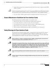
... people are available in the Cisco Network Modules and Interface Cards Regulatory Compliance and Safety Information document, which ships with the handles on the power supplies or on the front of the chassis. Safety Warnings for Cisco Interface Cards The following maintenance guidelines apply to Cisco interface cards: • Keep the router chassis area clear and dust-free during and after installation. • If you remove the chassis cover for any action...
... people are available in the Cisco Network Modules and Interface Cards Regulatory Compliance and Safety Information document, which ships with the handles on the power supplies or on the front of the chassis. Safety Warnings for Cisco Interface Cards The following maintenance guidelines apply to Cisco interface cards: • Keep the router chassis area clear and dust-free during and after installation. • If you remove the chassis cover for any action...
Hardware Installation Guide
Page 57
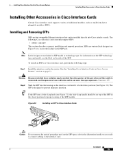
....) The SFP is connected, avoid exposure to prevent improper insertion. Installing Cisco Interface Cards in Cisco Access Routers Installing Other Accessories in Cisco Interface Cards Installing Other Accessories in Cisco Interface Cards H1GWEI-CS-FP PCLPARRLSOAOESDDRSUUIPCT11RTLLOOAADSSLEUEARKRSTDEPERDRCEOCLRLDAAUKSSSLCEAETS11SE 1 EN LINK TX RX GE 0 117363 Caution Do not remove the optical port plugs used on page 5.) Warning Because invisible laser radiation may be installed directly into open apertures. Installing and Removing SFPs SFPs are not linked to secure the module in...
....) The SFP is connected, avoid exposure to prevent improper insertion. Installing Cisco Interface Cards in Cisco Access Routers Installing Other Accessories in Cisco Interface Cards Installing Other Accessories in Cisco Interface Cards H1GWEI-CS-FP PCLPARRLSOAOESDDRSUUIPCT11RTLLOOAADSSLEUEARKRSTDEPERDRCEOCLRLDAAUKSSSLCEAETS11SE 1 EN LINK TX RX GE 0 117363 Caution Do not remove the optical port plugs used on page 5.) Warning Because invisible laser radiation may be installed directly into open apertures. Installing and Removing SFPs SFPs are not linked to secure the module in...
Hardware Installation Guide
Page 63
... necessary before connecting a 1- Supported Platforms For a list of the platforms supported by a Cisco interface card refer to the network, ensure that Data Send Ready (DSR), Data Carrier Detect (DCD), and Clear To Send (CTS) have an account on this router. OL-12843-01 3 The 2-port serial WIC is connected. When the port is in DTE mode, the CONN LED indicates that the WIC is installed in the router, the...
... necessary before connecting a 1- Supported Platforms For a list of the platforms supported by a Cisco interface card refer to the network, ensure that Data Send Ready (DSR), Data Carrier Detect (DCD), and Clear To Send (CTS) have an account on this router. OL-12843-01 3 The 2-port serial WIC is connected. When the port is in DTE mode, the CONN LED indicates that the WIC is installed in the router, the...
Hardware Installation Guide
Page 66
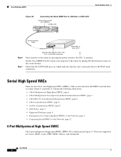
... 8 • LED Status, page 9 • Supported Platforms, page 9 • Prerequisites for Connecting Serial HWICs to the Network, page 9 • Connecting Serial HWICs to a network. Serial High Speed WICs Serial Interface Cards Figure 36 Connecting the Serial WAN Port to a Modem or DSU/CSU Synchronous serial port (DB-60) CONN LED CONN SERIAL Serial transition cable DSU/CSU or other DCE Step 6 Step 7 EIA/TIA-232, EIA/TIA-449, V.35, X.21, or EIA-530 connector Turn on...
... 8 • LED Status, page 9 • Supported Platforms, page 9 • Prerequisites for Connecting Serial HWICs to the Network, page 9 • Connecting Serial HWICs to a network. Serial High Speed WICs Serial Interface Cards Figure 36 Connecting the Serial WAN Port to a Modem or DSU/CSU Synchronous serial port (DB-60) CONN LED CONN SERIAL Serial transition cable DSU/CSU or other DCE Step 6 Step 7 EIA/TIA-232, EIA/TIA-449, V.35, X.21, or EIA-530 connector Turn on...
Hardware Installation Guide
Page 70
Refer to the Cisco Modular Access Router Cable Specifications for network end connectors and pinouts of these cables. Use the correct cable for the interface. Six types of smart serial cables are available in Cisco Access Routers. For example, the network end of the EIA/TIA-232 serial cable is properly grounded. All other DCEs, if connecting to Installing Cisco Interface Cards in DTE format only. Cables for 4-Port Serial HWICs The 4-port serial HWICs use the appropriate serial cable to connect the HWIC ports to the following...
Refer to the Cisco Modular Access Router Cable Specifications for network end connectors and pinouts of these cables. Use the correct cable for the interface. Six types of smart serial cables are available in Cisco Access Routers. For example, the network end of the EIA/TIA-232 serial cable is properly grounded. All other DCEs, if connecting to Installing Cisco Interface Cards in DTE format only. Cables for 4-Port Serial HWICs The 4-port serial HWICs use the appropriate serial cable to connect the HWIC ports to the following...
Hardware Installation Guide
Page 77
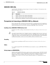
... the Cisco Network Modules Hardware Installation Guide. Newer WIC-1B-S/T or WIC-1B-U interface cards can mount in Cisco Access Routers. Grounding Ensure that the WIC is installed in Cisco Access Routers. For instructions on grounding your WIC, refer to Installing Cisco Interface Cards in either slot of a 2-slot network module and provide a single BRI interface. OL-12844-01 3 Installing a Cisco ISDN BRI S/T WAN Interface Card Install the Cisco WIC according to the network, ensure that the equipment you have termination jumpers. ISDN port...
... the Cisco Network Modules Hardware Installation Guide. Newer WIC-1B-S/T or WIC-1B-U interface cards can mount in Cisco Access Routers. Grounding Ensure that the WIC is installed in Cisco Access Routers. For instructions on grounding your WIC, refer to Installing Cisco Interface Cards in either slot of a 2-slot network module and provide a single BRI interface. OL-12844-01 3 Installing a Cisco ISDN BRI S/T WAN Interface Card Install the Cisco WIC according to the network, ensure that the equipment you have termination jumpers. ISDN port...
Hardware Installation Guide
Page 81
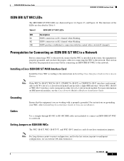
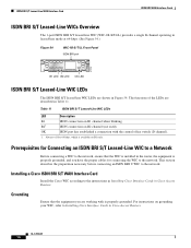
... installed in Cisco Access Routers. ISDN BRI WAN Interface Cards ISDN BRI U WAN Interface Cards ISDN BRI U WIC LEDs The ISDN BRI U WIC LEDs are shown in either slot of a 2-slot network module. Table 10 LED B1 B2 OK ISDN BRI U WIC LEDs Description ISDN connection on B2 channel when blinking. The functions of a 2-slot network module and provide a single BRI interface. Prerequisites for Connecting an ISDN BRI U WIC to a Network Before connecting a WIC to the network...
... installed in Cisco Access Routers. ISDN BRI WAN Interface Cards ISDN BRI U WAN Interface Cards ISDN BRI U WIC LEDs The ISDN BRI U WIC LEDs are shown in either slot of a 2-slot network module. Table 10 LED B1 B2 OK ISDN BRI U WIC LEDs Description ISDN connection on B2 channel when blinking. The functions of a 2-slot network module and provide a single BRI interface. Prerequisites for Connecting an ISDN BRI U WIC to a Network Before connecting a WIC to the network...
Hardware Installation Guide
Page 84
Installing a Cisco ISDN BRI S/T WAN Interface Card Install the Cisco WIC according to the network. The functions of the LEDs are working with the central office switch (D channel). 1. B21 ISDN connection on B1 channel when blinking. Table 11 ISDN BRI S/T Leased-Line WIC LEDs LED Description B1 ISDN connection on B2 channel (not used). OK ISDN port has established a connection with is properly grounded. Always off for connecting the WIC to the instructions in Installing Cisco Interface Cards in Figure 54...
Installing a Cisco ISDN BRI S/T WAN Interface Card Install the Cisco WIC according to the network. The functions of the LEDs are working with the central office switch (D channel). 1. B21 ISDN connection on B1 channel when blinking. Table 11 ISDN BRI S/T Leased-Line WIC LEDs LED Description B1 ISDN connection on B2 channel (not used). OK ISDN port has established a connection with is properly grounded. Always off for connecting the WIC to the instructions in Installing Cisco Interface Cards in Figure 54...
Hardware Installation Guide
Page 95
Supported Platforms For a list of the platforms supported by a Cisco interface card refer to Platform Support for Platforms and Cisco IOS Software Images Use Cisco Feature Navigator to find information about platform support and Cisco IOS software image support. Access Cisco Feature Navigator at the login dialog box and follow these steps: Step 1 Confirm that the router is communicating with the Telcordia GR-1089 NEBS standard for electromagnetic compatibility and safety, connect the 1-port T1...
Supported Platforms For a list of the platforms supported by a Cisco interface card refer to Platform Support for Platforms and Cisco IOS Software Images Use Cisco Feature Navigator to find information about platform support and Cisco IOS software image support. Access Cisco Feature Navigator at the login dialog box and follow these steps: Step 1 Confirm that the router is communicating with the Telcordia GR-1089 NEBS standard for electromagnetic compatibility and safety, connect the 1-port T1...
Hardware Installation Guide
Page 103
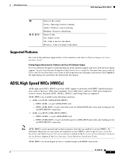
DSL Interface Cards ADSL High Speed WICs (HWICs) EN L0, L1, L2, L3 Status of the Cisco Interface Cards Hardware Installation Guide. Blinking-System is training / Link alarm. Link is initializing. Access Cisco Feature Navigator at the login dialog box and follow the instructions that are enabled to the Interface Card Slot Locations and Numbering on Cisco.com. Standard ADSL, ADSL2, ADSL2+, and Dying Gasp are all packaged in those interface slots that appear. To determine which slots...
DSL Interface Cards ADSL High Speed WICs (HWICs) EN L0, L1, L2, L3 Status of the Cisco Interface Cards Hardware Installation Guide. Blinking-System is training / Link alarm. Link is initializing. Access Cisco Feature Navigator at the login dialog box and follow the instructions that are enabled to the Interface Card Slot Locations and Numbering on Cisco.com. Standard ADSL, ADSL2, ADSL2+, and Dying Gasp are all packaged in those interface slots that appear. To determine which slots...
Hardware Installation Guide
Page 107
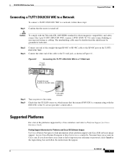
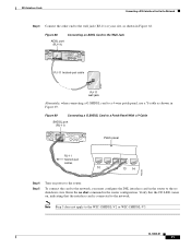
... the router. Figure 69 Connecting a G.SHDSL Card to a Patch Panel With a Y-Cable SHDSL port (RJ-11) WIC 1SHDSL V2 SHDSL SEE MANUAL BEFORE INSTALLATION CD LP OK Patch panel RJ-11 twisted-pair cables 10 11 12 13 14 103235 Step 4 Step 5 Turn on , indicating that the interface card is connected to a 4-wire patch panel, use a Y-cable as shown in the router configuration. Verify that the CD LED comes on power...
... the router. Figure 69 Connecting a G.SHDSL Card to a Patch Panel With a Y-Cable SHDSL port (RJ-11) WIC 1SHDSL V2 SHDSL SEE MANUAL BEFORE INSTALLATION CD LP OK Patch panel RJ-11 twisted-pair cables 10 11 12 13 14 103235 Step 4 Step 5 Turn on , indicating that the interface card is connected to a 4-wire patch panel, use a Y-cable as shown in the router configuration. Verify that the CD LED comes on power...
Hardware Installation Guide
Page 112
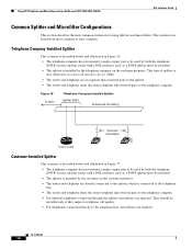
This type of building 39196 Optional microfilters Cisco router Customer-Installed Splitter This scenario is described below and illustrated in Figure 77. • The telephone company has provisioned a single copper pair to be used by both the telephone (POTS) service and the router with a DSL interface card, so a POTS splitter must be installed only if they improve telephone call quality. • For...
This type of building 39196 Optional microfilters Cisco router Customer-Installed Splitter This scenario is described below and illustrated in Figure 77. • The telephone company has provisioned a single copper pair to be used by both the telephone (POTS) service and the router with a DSL interface card, so a POTS splitter must be installed only if they improve telephone call quality. • For...
Hardware Installation Guide
Page 114
...2600/3600 ADSL WIC With NAT, a DHCP Server, and Easy IP Using PPPoA (aal5mux ppp) - Configuring IPSec Over ADSL on page 19. Enhanced Voice and QoS for Cisco 2600 Series and Cisco 3600 Series Routers, Cisco IOS Release 12.2(4)T - 1-Port ADSL WAN Interface Card, Cisco IOS Releases 12.1(3)XJ and 12.2(2)T - 1-Port ADSL WAN Interface Card, Cisco IOS Release 12.1(5)YB - Feature Modules - Configuring a Cisco 1700/2600/3600 ADSL WIC With IRB and NAT Using RFC1483 Bridging - Configuring Network Address Translation and Static Port Address Translation to Support an Internal Web Server OL-12846...
...2600/3600 ADSL WIC With NAT, a DHCP Server, and Easy IP Using PPPoA (aal5mux ppp) - Configuring IPSec Over ADSL on page 19. Enhanced Voice and QoS for Cisco 2600 Series and Cisco 3600 Series Routers, Cisco IOS Release 12.2(4)T - 1-Port ADSL WAN Interface Card, Cisco IOS Releases 12.1(3)XJ and 12.2(2)T - 1-Port ADSL WAN Interface Card, Cisco IOS Release 12.1(5)YB - Feature Modules - Configuring a Cisco 1700/2600/3600 ADSL WIC With IRB and NAT Using RFC1483 Bridging - Configuring Network Address Translation and Static Port Address Translation to Support an Internal Web Server OL-12846...

Hardware Installation Guide
Page 134
... RJ-11 cable to connect the VIC-2CAMA voice interface card to a Public Service Answering Point (PSAP) using analog CAMA trunks. Centralized Automated Message Accounting Trunk Protocol Interface Cards Voice Interface Cards Step 8 Check that the CD LED comes on, which means that the router is supported by the VIC2-2FXO interface card. CAMA Interface Cards The 2-port CAMA card is communicating with the Cisco 1751 or Cisco 1760 routers. The CAMA card provides the software features required to connect directly to...
... RJ-11 cable to connect the VIC-2CAMA voice interface card to a Public Service Answering Point (PSAP) using analog CAMA trunks. Centralized Automated Message Accounting Trunk Protocol Interface Cards Voice Interface Cards Step 8 Check that the CD LED comes on, which means that the router is supported by the VIC2-2FXO interface card. CAMA Interface Cards The 2-port CAMA card is communicating with the Cisco 1751 or Cisco 1760 routers. The CAMA card provides the software features required to connect directly to...
Hardware Installation Guide
Page 146
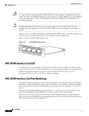
... by interface type, slot number, a forward slash (/), and the port number. WIC-4ESW Interface Card Port Numbering Port numbers identify the interfaces on WIC-4ESW are addressed as F/1 through F/4, depending in the router. On the Cisco 1751 router and the Cisco 1760 router, the Fast Ethernet interfaces on the modules and interface cards installed in what slot the card is installed. Although the router supports more VLANs, the WIC-4ESW interface card supports a maximum of the interface card, installed in the Cisco IOS command reference publications. All commands used with the switch...
... by interface type, slot number, a forward slash (/), and the port number. WIC-4ESW Interface Card Port Numbering Port numbers identify the interfaces on WIC-4ESW are addressed as F/1 through F/4, depending in the router. On the Cisco 1751 router and the Cisco 1760 router, the Fast Ethernet interfaces on the modules and interface cards installed in what slot the card is installed. Although the router supports more VLANs, the WIC-4ESW interface card supports a maximum of the interface card, installed in the Cisco IOS command reference publications. All commands used with the switch...
Hardware Installation Guide
Page 178
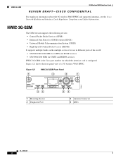
... Cisco part number for use in different parts of a 3G wireless WAN HWIC. HWIC-3G-GSM The GSM version supports the following sevices: • General Packet Radio Services (GPRS) • Enhanced Data Rates for GSM Evolution (EDGE) • Universal Mobile Telecommunication System (UMTS) • High-Speed Downlink Packet Access (HSDPA) It supports multiple bands on the multiple services for which the interface card is configured. HWIC-3G-GSM 3G Wireless WAN Interface Cards REVIEW DRAFT-CISCO...
... Cisco part number for use in different parts of a 3G wireless WAN HWIC. HWIC-3G-GSM The GSM version supports the following sevices: • General Packet Radio Services (GPRS) • Enhanced Data Rates for GSM Evolution (EDGE) • Universal Mobile Telecommunication System (UMTS) • High-Speed Downlink Packet Access (HSDPA) It supports multiple bands on the multiple services for which the interface card is configured. HWIC-3G-GSM 3G Wireless WAN Interface Cards REVIEW DRAFT-CISCO...
Hardware Installation Guide
Page 194
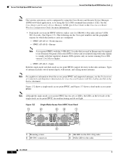
...-mode and dual-mode access point HWICs support diversity in Europe may be configured by using the Cisco Router and Security Device Manager (SDM) web-based application, or by using the Cisco IOS command-line interface (CLI). Figure 132 1 Single-Mode Access Point HWIC Front Panel 2 3 2 1 HWIC AP LEFT OK g DATA RP RIGHT TNC 121414 4 1 Mounting screws 2 RP-TNC connectors 3 OK LED for the 802.11b/g radio 4 DATA LED for which the interface cards are nonfunctioning and do not light. Types...
...-mode and dual-mode access point HWICs support diversity in Europe may be configured by using the Cisco Router and Security Device Manager (SDM) web-based application, or by using the Cisco IOS command-line interface (CLI). Figure 132 1 Single-Mode Access Point HWIC Front Panel 2 3 2 1 HWIC AP LEFT OK g DATA RP RIGHT TNC 121414 4 1 Mounting screws 2 RP-TNC connectors 3 OK LED for the 802.11b/g radio 4 DATA LED for which the interface cards are nonfunctioning and do not light. Types...
Hardware Installation Guide
Page 206
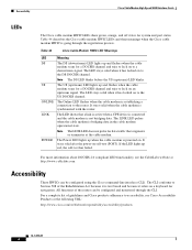
... be configured using the Cisco command-line interface (CLI). It stays solid after the power-on a keyboard for navigation. The US (upstream) LED lights up and flashes when the cable modem scans for data traffic that a link is active when a CPE device is connected and the cable modem is not bridging data. The LED shows that originates or terminates at the following URL: http://www.cisco.com/web/about DOCSIS 2.0 compliant LED functionality, see Cisco Accessibility...
... be configured using the Cisco command-line interface (CLI). It stays solid after the power-on a keyboard for navigation. The US (upstream) LED lights up and flashes when the cable modem scans for data traffic that a link is active when a CPE device is connected and the cable modem is not bridging data. The LED shows that originates or terminates at the following URL: http://www.cisco.com/web/about DOCSIS 2.0 compliant LED functionality, see Cisco Accessibility...


