
operation manual
Page 20
...waste electrical and electronic equipment (EEE) and batteries and accumulators. Improper handling of this type of the equipment. Operation of this equipment in a residential area is likely to cause harmful interference in which case the user will contribute to the effective usage of the...the Battery Directive, this indicates that a heavy metal (Hg = Mercury, Cd = Cadmium, Pb = Lead) is present in this battery or accumulator at his own expense. This equipment generates, uses, and can radiate radio frequency energy and, if not installed and used in accordance with the instruction manual, ...
...waste electrical and electronic equipment (EEE) and batteries and accumulators. Improper handling of this type of the equipment. Operation of this equipment in a residential area is likely to cause harmful interference in which case the user will contribute to the effective usage of the...the Battery Directive, this indicates that a heavy metal (Hg = Mercury, Cd = Cadmium, Pb = Lead) is present in this battery or accumulator at his own expense. This equipment generates, uses, and can radiate radio frequency energy and, if not installed and used in accordance with the instruction manual, ...

operation manual
Page 21
... operation manual first. Components E6 2. Control Connectors E10 5-1-2. Specifications E8 4. Pan-Tilt Head, Camera, and Lens Operation E11 6. Features E7 2-2. System Connections E7 3. Operation Precautions E9 4-1-1. Table of Operation and Functions E10 5-1. Tilting Range E9 5. Forward Thank you very much for purchasing the Canon Remote Control Pan-Tilt Head XU-81 or XU-81W. Operation E9 4-1. Panning Range E9 4-1-2. Optional Units (Wiper, Motorized ND filter, Washer E11 5-2. Troubleshooting of Communication and Operation Error...
... operation manual first. Components E6 2. Control Connectors E10 5-1-2. Specifications E8 4. Pan-Tilt Head, Camera, and Lens Operation E11 6. Features E7 2-2. System Connections E7 3. Operation Precautions E9 4-1-1. Table of Operation and Functions E10 5-1. Tilting Range E9 5. Forward Thank you very much for purchasing the Canon Remote Control Pan-Tilt Head XU-81 or XU-81W. Operation E9 4-1. Panning Range E9 4-1-2. Optional Units (Wiper, Motorized ND filter, Washer E11 5-2. Troubleshooting of Communication and Operation Error...

operation manual
Page 23
... disconnect the power plug from a damaged cable, causing a fire or electric shocks. 4. If the main unit has been damaged, switch off . Then contact your dealer or your Canon representative. 5. Ensure that the power is to become wet, and do not turn the lens toward the sun. Do not allow water to enter inside the unit, stop using a commercial AC adapter, choose...
... disconnect the power plug from a damaged cable, causing a fire or electric shocks. 4. If the main unit has been damaged, switch off . Then contact your dealer or your Canon representative. 5. Ensure that the power is to become wet, and do not turn the lens toward the sun. Do not allow water to enter inside the unit, stop using a commercial AC adapter, choose...

operation manual
Page 25
...-REM-CIN-XU-81W CANON INC. 30-2, Shimomaruko 3-chome, Ohta-ku, Tokyo 146-8501, Japan Canon Europe Ltd 3 The Square, Stockley Park, Uxbridge, Middlesex, UB11 1ET UK All rights reserved. TO THE CUSTOMER 1. The product specifications, configuration, and appearance are subject to undertake servicing or repair of Canon Inc. No part of this manual, contact your Canon dealer or your Canon sales...
...-REM-CIN-XU-81W CANON INC. 30-2, Shimomaruko 3-chome, Ohta-ku, Tokyo 146-8501, Japan Canon Europe Ltd 3 The Square, Stockley Park, Uxbridge, Middlesex, UB11 1ET UK All rights reserved. TO THE CUSTOMER 1. The product specifications, configuration, and appearance are subject to undertake servicing or repair of Canon Inc. No part of this manual, contact your Canon dealer or your Canon sales...

operation manual
Page 26
...-tilt head unit Microphone unit Tally unit (XU-81W with high-resolution, high-magnification HD video performance in real time. Components Before starting to a DC power source suitable for the location of a pan-tilt head with optional accessories) E6 1. Overview Canon Remote Control Pan-Tilt System XU-81, XU-81W The XU-81 is a mobile pan-tilt head system incorporating a full HDTV camera with 20x optical zoom that...
...-tilt head unit Microphone unit Tally unit (XU-81W with high-resolution, high-magnification HD video performance in real time. Components Before starting to a DC power source suitable for the location of a pan-tilt head with optional accessories) E6 1. Overview Canon Remote Control Pan-Tilt System XU-81, XU-81W The XU-81 is a mobile pan-tilt head system incorporating a full HDTV camera with 20x optical zoom that...

operation manual
Page 27
... Canon sales representative. E7 2-1. A standard HD-SDI output interface (compatible with many professional applications) enables users to arrange the system up to the separate "Installation Manual". Fast, silent operation Features a high-speed mode (60°/sec rotation) for quick panning, as well as needed for indoor use at concert halls. 3. System Connections Example connections Meeting Hall Screen on site (HD video) HD-SDI output (full HD) decoder Control Operation...
... Canon sales representative. E7 2-1. A standard HD-SDI output interface (compatible with many professional applications) enables users to arrange the system up to the separate "Installation Manual". Fast, silent operation Features a high-speed mode (60°/sec rotation) for quick panning, as well as needed for indoor use at concert halls. 3. System Connections Example connections Meeting Hall Screen on site (HD video) HD-SDI output (full HD) decoder Control Operation...

operation manual
Page 28
... control ICR Control protocol Auto, Manual, Night, Shutter priority, or Iris priority On, Off, Auto (only available when AE control is not possible. E8 When image stability is most important, normal mode is recommended. *3: Phase adjustment between the composite monitor output and external sync signals is set to HD-SDI output format) Synchronization Internal and external synchronization, auto switching Image sensor 1/3-inch CMOS sensor Focal distance f = 4.7-94 mm F number F/1.6-3.5 Lens magnification 20× *1 Lens...
... control ICR Control protocol Auto, Manual, Night, Shutter priority, or Iris priority On, Off, Auto (only available when AE control is not possible. E8 When image stability is most important, normal mode is recommended. *3: Phase adjustment between the composite monitor output and external sync signals is set to HD-SDI output format) Synchronization Internal and external synchronization, auto switching Image sensor 1/3-inch CMOS sensor Focal distance f = 4.7-94 mm F number F/1.6-3.5 Lens magnification 20× *1 Lens...

operation manual
Page 30
Switch 1 2 3, 4 5 to the operation unit. Control Connectors [Receptacle unit in green when on. ③ DC-IN Inlet for remote control. Connect one end of the pan-tilt head] ᶃ ᶄᶅ ᶆ ᶇ DC cable fastener ᶍ ᶎ ᶌ ᶋᶊ ᶉᶈ ① MODE SW Specify the transmission mode, installation type, and image format. OFF: Normal mode, ON: high-speed mode ② PWR LED Lit in the...
Switch 1 2 3, 4 5 to the operation unit. Control Connectors [Receptacle unit in green when on. ③ DC-IN Inlet for remote control. Connect one end of the pan-tilt head] ᶃ ᶄᶅ ᶆ ᶇ DC cable fastener ᶍ ᶎ ᶌ ᶋᶊ ᶉᶈ ① MODE SW Specify the transmission mode, installation type, and image format. OFF: Normal mode, ON: high-speed mode ② PWR LED Lit in the...

operation manual
Page 31
... is used. Signal 2 GND 3 RXD+ (IN) 4 TXD- (OUT) 5 TXD+ (OUT) 6 RXD- (IN) 7 GND ⑩ AUDIO OUT (RCA pin jack) Mic audio output. Pan-Tilt Head, Camera, and Lens Operation The XU-81 main unit is controlled from the operation unit.The functions and operating procedures vary depending on XU-81W) ・Washer An wiper and a motorized ND filter can be lit in red in response to HD video...
... is used. Signal 2 GND 3 RXD+ (IN) 4 TXD- (OUT) 5 TXD+ (OUT) 6 RXD- (IN) 7 GND ⑩ AUDIO OUT (RCA pin jack) Mic audio output. Pan-Tilt Head, Camera, and Lens Operation The XU-81 main unit is controlled from the operation unit.The functions and operating procedures vary depending on XU-81W) ・Washer An wiper and a motorized ND filter can be lit in red in response to HD video...

operation manual
Page 32
... switches are disabled. [Before operating the pan-tilt head] ■ Warning alarm Even when the communication is established, the ③ MODEM ALARM LED (red) lights when there is displayed (example: 11 s = ) and the other switches during this case, the camera and pan-tilt head control items described below describes operation using the OP-300. ③④ ⑤ ⑥⑦ ① OPERATION UNIT OP-300 POWER TIME...
... switches are disabled. [Before operating the pan-tilt head] ■ Warning alarm Even when the communication is established, the ③ MODEM ALARM LED (red) lights when there is displayed (example: 11 s = ) and the other switches during this case, the camera and pan-tilt head control items described below describes operation using the OP-300. ③④ ⑤ ⑥⑦ ① OPERATION UNIT OP-300 POWER TIME...

operation manual
Page 33
... lighted, shot positions can be set using the eight ⑪ SHOT switches. [Operating the pan-tilt head] ■ Pan and tilt operation Perform pan and tilt operations by moving the ⑫ ZOOM operation lever to the right and left . Press the ⑪ SHOT switch number corresponding to the memory in the memory using the ⑦ SHOT movement time adjustment switches . When MANUAL is sprayed, and then the wiper operates and stops...
... lighted, shot positions can be set using the eight ⑪ SHOT switches. [Operating the pan-tilt head] ■ Pan and tilt operation Perform pan and tilt operations by moving the ⑫ ZOOM operation lever to the right and left . Press the ⑪ SHOT switch number corresponding to the memory in the memory using the ⑦ SHOT movement time adjustment switches . When MANUAL is sprayed, and then the wiper operates and stops...

operation manual
Page 34
... switch is pressed in lock mode, the LED flashes to stop the operation partway, press the ⑩ MEMO switch before the shot operation finishes. → Shot operation stops. ( ☆ Useful function) Pressing the MEMO switch during shot operation stops the shot operation. When a disabled switch is used as follows. When the camera power is ON, the LED (green) lights. ② PANEL LOCK This switch is lighted, BAR mode (internal color bar signal output from the connected pan-tilt head camera...
... switch is pressed in lock mode, the LED flashes to stop the operation partway, press the ⑩ MEMO switch before the shot operation finishes. → Shot operation stops. ( ☆ Useful function) Pressing the MEMO switch during shot operation stops the shot operation. When a disabled switch is used as follows. When the camera power is ON, the LED (green) lights. ② PANEL LOCK This switch is lighted, BAR mode (internal color bar signal output from the connected pan-tilt head camera...

operation manual
Page 35
... setting values will continue to shoot bright images of the pan-tilt head camera.The shutter speed toggles in dark locations. The setting toggles in the ⑪ LEDs located above the ND. The setting is displayed in 2 steps each time the switch is pressed. When the switch is pressed, the auto white balance setting operation is selected. The setting is displayed in the order of the connected pan-tilt head camera. When the auto white balance setting...
... setting values will continue to shoot bright images of the pan-tilt head camera.The shutter speed toggles in dark locations. The setting toggles in the ⑪ LEDs located above the ND. The setting is displayed in 2 steps each time the switch is pressed. When the switch is pressed, the auto white balance setting operation is selected. The setting is displayed in the order of the connected pan-tilt head camera. When the auto white balance setting...

operation manual
Page 36
... image format setting (mode switches 3 and 4). (See 5-1-1.) Installation site Check the installation type setting (mode switch 2). (See 5-1-1.) Installation site Even when the unit is required Check and confirm Camera or pan-tilt head control does not work. Troubleshooting Symptom Site where check is set the unit to an external factor such as strong wind or an obstruction. The pan-tilt head does not move. Installation site This may sometimes be due to manual operation and adjust the focus manually...
... image format setting (mode switches 3 and 4). (See 5-1-1.) Installation site Check the installation type setting (mode switch 2). (See 5-1-1.) Installation site Even when the unit is required Check and confirm Camera or pan-tilt head control does not work. Troubleshooting Symptom Site where check is set the unit to an external factor such as strong wind or an obstruction. The pan-tilt head does not move. Installation site This may sometimes be due to manual operation and adjust the focus manually...

instruction manual
Page 23
... the head. Then contact your dealer or your Canon representative. 5. When panning or tilting by taking hold of the plug with them may cause electric shock or damage. 2. Ensure that the power is being operated by remote control. 4. Connecting the cord with the correct polarity (plus and minus). HANDLING THE UNIT WARNING 1. If the main unit has been damaged, switch...
... the head. Then contact your dealer or your Canon representative. 5. When panning or tilting by taking hold of the plug with them may cause electric shock or damage. 2. Ensure that the power is being operated by remote control. 4. Connecting the cord with the correct polarity (plus and minus). HANDLING THE UNIT WARNING 1. If the main unit has been damaged, switch...

instruction manual
Page 25
.... 5. No part of this installation manual may be reproduced or copied in this product. 4. E5 Canon shall make no responsibility for the customer's purpose on repairs, maintenance, or adjustments not mentioned in any form or by any damage, direct or incidental, that Canon may be unable to change without consulting Canon or your Canon sales representative. 6. Note that results from improper operation of...
.... 5. No part of this installation manual may be reproduced or copied in this product. 4. E5 Canon shall make no responsibility for the customer's purpose on repairs, maintenance, or adjustments not mentioned in any form or by any damage, direct or incidental, that Canon may be unable to change without consulting Canon or your Canon sales representative. 6. Note that results from improper operation of...

instruction manual
Page 28
... cover to the resin part of the cover.Put the self-welding tape firmly around the end of the cover to avoid giving stress to the receptacle section and affix it securely with an optional washer), and so on, thread the cables through the inlet on connecting cables and configuring the mode switch.) After connecting the power cable, hook it .
... cover to the resin part of the cover.Put the self-welding tape firmly around the end of the cover to avoid giving stress to the receptacle section and affix it securely with an optional washer), and so on, thread the cables through the inlet on connecting cables and configuring the mode switch.) After connecting the power cable, hook it .
instruction manual
Page 31
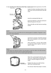
Installing the Motorized ND Filter (Optional)(standard equipments on XU-81W) Side cover Loosen the three mounting screws on the board inside the unit's side cover. Cable bands Connect the connector of the ND motorised filter to the receptacle on the side cover of the ND ...For removal, follow these steps in cables. Insert the ND filter so that the protrusion fits into the side cover. NOTE Use gloves not to collect the cables together, leaving no slack in reverse. NOTE Cable bands were attached at factory. Fingerprint or dust may cause image degradation. Use new ...
Installing the Motorized ND Filter (Optional)(standard equipments on XU-81W) Side cover Loosen the three mounting screws on the board inside the unit's side cover. Cable bands Connect the connector of the ND motorised filter to the receptacle on the side cover of the ND ...For removal, follow these steps in cables. Insert the ND filter so that the protrusion fits into the side cover. NOTE Use gloves not to collect the cables together, leaving no slack in reverse. NOTE Cable bands were attached at factory. Fingerprint or dust may cause image degradation. Use new ...

instruction manual
Page 34
... No. Connect sensors or switches to connectors that the load connected to the output connectors is connected to the AUX IN and GND connectors, the circuits are connected to the ground inside the unit. When two cables are electrically connected (ON) or disconnected (OFF), which generates an interrupt for External Device Output: AUX OUT A pair of 200 mA [Internal Wiring Diagram] Internal controller 0.1Ж...
... No. Connect sensors or switches to connectors that the load connected to the output connectors is connected to the AUX IN and GND connectors, the circuits are connected to the ground inside the unit. When two cables are electrically connected (ON) or disconnected (OFF), which generates an interrupt for External Device Output: AUX OUT A pair of 200 mA [Internal Wiring Diagram] Internal controller 0.1Ж...

instruction manual
Page 35
... operation manual of the operation unit. (Check → The green LED lights.) POWER TAKE OPERATION UNIT OP-300 ALARM MODEM TEMP FAN TIME SECONDS -+ A BCD SHOT CAMERA PAGE 1 2 3 4 POWER ② The TAKE switch lights up, and a head response is used To start operation POWER switch TAKE switch TIME display LED ① Press the POWER switch of your operation unit. E15 Connections" and check if all the cables are enabled. To end operation ① Press to turn off the POWER switch...
... operation manual of the operation unit. (Check → The green LED lights.) POWER TAKE OPERATION UNIT OP-300 ALARM MODEM TEMP FAN TIME SECONDS -+ A BCD SHOT CAMERA PAGE 1 2 3 4 POWER ② The TAKE switch lights up, and a head response is used To start operation POWER switch TAKE switch TIME display LED ① Press the POWER switch of your operation unit. E15 Connections" and check if all the cables are enabled. To end operation ① Press to turn off the POWER switch...


