
Service Manual
Page 3
... required for adjustment and troubleshooting and service operations and service switches. Chapter 4: Appendix This part explains the informations of the optional products and user data flow. • For more details of user operations and user reports, see the separate volume of USER'S GUIDE. • Greasing points is not given in this manual. II. II Chapter 3: Maintenance and Service This part explains how to this model. See G3 Facsimile Service Data Handbook (supplied...
... required for adjustment and troubleshooting and service operations and service switches. Chapter 4: Appendix This part explains the informations of the optional products and user data flow. • For more details of user operations and user reports, see the separate volume of USER'S GUIDE. • Greasing points is not given in this manual. II. II Chapter 3: Maintenance and Service This part explains how to this model. See G3 Facsimile Service Data Handbook (supplied...
Service Manual
Page 6
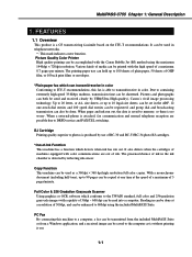
... Manual/Auto Reception Switching 5.3.1 Settings 5.3.2 Parameters 5.4 Operations Where Other Machine Does not Have Color Communications Ability 5.5 Conditions Necessary for Color Reception 5.6 Specifications for processing communication problems 5. ADJUSTMENT 3.1 CS LED Lights-on the Display 4.3.1 General errors 4.3.2 Printing problems 4.3.3 Scanning problems 4.4 Processing Communication Problems 4.4.1 Initial identification of problems 4.4.2 Procedures for Color Communications 6. TROUBLESHOOTING 4.1 Troubleshooting Index 4.2 Errors Shown on the Display 4.2.1 User error message 4.2.2 Error...
... Manual/Auto Reception Switching 5.3.1 Settings 5.3.2 Parameters 5.4 Operations Where Other Machine Does not Have Color Communications Ability 5.5 Conditions Necessary for Color Reception 5.6 Specifications for processing communication problems 5. ADJUSTMENT 3.1 CS LED Lights-on the Display 4.3.1 General errors 4.3.2 Printing problems 4.3.3 Scanning problems 4.4 Processing Communication Problems 4.4.1 Initial identification of problems 4.4.2 Procedures for Color Communications 6. TROUBLESHOOTING 4.1 Troubleshooting Index 4.2 Errors Shown on the Display 4.2.1 User error message 4.2.2 Error...
Service Manual
Page 8
... of ink. Full Color & 256 Gradation Grayscale Scanner Using graphics or OCR software which detects when ink has run out, the data is saved to memory, so there is able to a computer, a fax can be transmitted from the included MultiPASS Suite or from a Windows application, and a received image can be used as -is without printing it out. 1-1 Various kinds of media can be printed with color communications...
... of ink. Full Color & 256 Gradation Grayscale Scanner Using graphics or OCR software which detects when ink has run out, the data is saved to memory, so there is able to a computer, a fax can be transmitted from the included MultiPASS Suite or from a Windows application, and a received image can be used as -is without printing it out. 1-1 Various kinds of media can be printed with color communications...

Service Manual
Page 13
...) Ink detection Optical LOW-Ink sense Printing speed Black Approx. 8.7 pages/minute (in a checkered pattern without printing vertical and horizontal adjacent dots. Paper output tray stacking Approx. 50 sheets (when using the recommended paper) Paper tray Paper supply method ASF (Auto Sheet Feeder) Number of character print) Color Approx. 4.6 page/minute Printing resolution 360 dpi × 360 dpi (Normal print), 1440 dpi × 720 dpi (Printer mode) 180 dpi × 180 dpi (Economy print*) *Printing in case of paper tray 1tray...
...) Ink detection Optical LOW-Ink sense Printing speed Black Approx. 8.7 pages/minute (in a checkered pattern without printing vertical and horizontal adjacent dots. Paper output tray stacking Approx. 50 sheets (when using the recommended paper) Paper tray Paper supply method ASF (Auto Sheet Feeder) Number of character print) Color Approx. 4.6 page/minute Printing resolution 360 dpi × 360 dpi (Normal print), 1440 dpi × 720 dpi (Printer mode) 180 dpi × 180 dpi (Economy print*) *Printing in case of paper tray 1tray...

Service Manual
Page 21
...digit code to (manual document feed) for the document you are sending. MultiPASS C755 Chapter 1: General Description 3.2 Operation Panel Operation Panel s Numeric Buttons Enter numbers when dialing or registering fax/telephone numbers. Also enter characters when registering names. s Color/B&W Button Sets the unit for one-touch speed dialing. s Alarm Light Flashes when an error occurs, or when the MultiPASS is out of paper or ink. s Copy Button Sets the MultiPASS to standby mode. s Stop Button Cancels sending, receiving, registering data, copying and other operations...
...digit code to (manual document feed) for the document you are sending. MultiPASS C755 Chapter 1: General Description 3.2 Operation Panel Operation Panel s Numeric Buttons Enter numbers when dialing or registering fax/telephone numbers. Also enter characters when registering names. s Color/B&W Button Sets the unit for one-touch speed dialing. s Alarm Light Flashes when an error occurs, or when the MultiPASS is out of paper or ink. s Copy Button Sets the MultiPASS to standby mode. s Stop Button Cancels sending, receiving, registering data, copying and other operations...

Service Manual
Page 40
Therefore, when replacing the operation panel assembly, you need to purchase the operation panel unit and operation panel sheet and then attach the operation panel sheet onto the operation panel unit. Figure 2-11 Operation Panel Sheet Attachment 2-13 MultiPASS C755 Chapter 2: Assembly and Disassembly Disassembly 7. b a Figure 2-10 Disassembly 7 NOTE Attachment of operation panel sheet The service part unit configuration of the operation panel, adjust the position and then stick it will be used with the operation panel sheet attached. Align the upper edge of the sheet against the...
Therefore, when replacing the operation panel assembly, you need to purchase the operation panel unit and operation panel sheet and then attach the operation panel sheet onto the operation panel unit. Figure 2-11 Operation Panel Sheet Attachment 2-13 MultiPASS C755 Chapter 2: Assembly and Disassembly Disassembly 7. b a Figure 2-10 Disassembly 7 NOTE Attachment of operation panel sheet The service part unit configuration of the operation panel, adjust the position and then stick it will be used with the operation panel sheet attached. Align the upper edge of the sheet against the...
Service Manual
Page 52
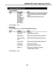
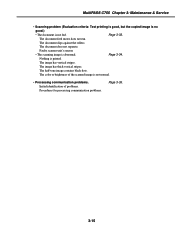
... CLEAN PARTS on page 3-4. Document feed/eject roller When document feed/eject performance deteriorates. Service Technician None 3-1 MAINTENANCE LIST 1.1 Consumables Level Consumable User BJ cartridge (BC-30/BC-33 /BC-34 Photo) INK tank (BCI-3BK/BCI-3C /BCI-3M/BCI-3Y /BCI-3BK Photo /BCI-3C Photo /BCI-3M Photo) When When normal images are not output even after inserting ink into the ink tank and performing repeated HEAD cleaning. Scanning glass (contact sensor) When black...
... CLEAN PARTS on page 3-4. Document feed/eject roller When document feed/eject performance deteriorates. Service Technician None 3-1 MAINTENANCE LIST 1.1 Consumables Level Consumable User BJ cartridge (BC-30/BC-33 /BC-34 Photo) INK tank (BCI-3BK/BCI-3C /BCI-3M/BCI-3Y /BCI-3BK Photo /BCI-3C Photo /BCI-3M Photo) When When normal images are not output even after inserting ink into the ink tank and performing repeated HEAD cleaning. Scanning glass (contact sensor) When black...
Service Manual
Page 53
... this fax. When the machine's power switch is turned on, the data stored in SRAM is checked for the presence/absence of a document, and if there is no document, exposure control is performed automatically. When a document is present, scanning is done in SRAM has been lost, adjustment of CS-LED lights-on duration is automatically performed at that there is an abnormality. 3-2 MultiPASS C755 Chapter 3: Maintenance & Service 1.3 Periodic...
... this fax. When the machine's power switch is turned on, the data stored in SRAM is checked for the presence/absence of a document, and if there is no document, exposure control is performed automatically. When a document is present, scanning is done in SRAM has been lost, adjustment of CS-LED lights-on duration is automatically performed at that there is an abnormality. 3-2 MultiPASS C755 Chapter 3: Maintenance & Service 1.3 Periodic...
Service Manual
Page 66
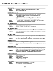
... document feed motor does not run. Faulty scanner unit's sensors • The scanning image is printed. Nothing is abnormal. The image has vertical stripes. The image has thick vertical stripes. Page 3-33. Page 3-34. The document does not separate. The half-tone image contains black dots. The color or brightness of problems. Procedures for processing communication problems. Page 3-35. 3-15 MultiPASS C755 Chapter 3: Maintenance & Service • Scanning problem (Evaluation criteria: Test printing is good, but the copied image...
... document feed motor does not run. Faulty scanner unit's sensors • The scanning image is printed. Nothing is abnormal. The image has vertical stripes. The image has thick vertical stripes. Page 3-33. Page 3-34. The document does not separate. The half-tone image contains black dots. The color or brightness of problems. Procedures for processing communication problems. Page 3-35. 3-15 MultiPASS C755 Chapter 3: Maintenance & Service • Scanning problem (Evaluation criteria: Test printing is good, but the copied image...

Service Manual
Page 69
.... (2) Replace the lithium battery. (3) Replace the SPCNT board. 3-18 "CHECK PAPER SIZE" Cause: The size of the feed operation. Solution: Clear the paper jam and press the Resume button. "DATA ERROR" Cause: Solutions: The registration data in the SRAM was destroyed and a checksum error occurred due to cancel. MultiPASS C755 Chapter 3: Maintenance & Service "CHANGE CARTRIDGE" Cause: The printer cover is open and the cartridge holder is moving to black & white and print it is all right to convent a color document...
.... (2) Replace the lithium battery. (3) Replace the SPCNT board. 3-18 "CHECK PAPER SIZE" Cause: The size of the feed operation. Solution: Clear the paper jam and press the Resume button. "DATA ERROR" Cause: Solutions: The registration data in the SRAM was destroyed and a checksum error occurred due to cancel. MultiPASS C755 Chapter 3: Maintenance & Service "CHANGE CARTRIDGE" Cause: The printer cover is open and the cartridge holder is moving to black & white and print it is all right to convent a color document...
Service Manual
Page 71
... correct number. "MEMORY FULL" (#037) Cause: The fax's memory is empty. MultiPASS C755 Chapter 3: Maintenance & Service "M INK EMPTY" Cause: Solution: The Mazenta BJ tank in the Color or Photo BJ cartridge is full because it is not set incorrectly. Solution: (1) Print out any corrections needed, then try again. Replace the Mazenta BJ tank. Cause: The fax's memory is full because you don't need, delete them to put paper in their machine...
... correct number. "MEMORY FULL" (#037) Cause: The fax's memory is empty. MultiPASS C755 Chapter 3: Maintenance & Service "M INK EMPTY" Cause: Solution: The Mazenta BJ tank in the Color or Photo BJ cartridge is full because it is not set incorrectly. Solution: (1) Print out any corrections needed, then try again. Replace the Mazenta BJ tank. Cause: The fax's memory is full because you don't need, delete them to put paper in their machine...
Service Manual
Page 74
....02 to "1". Set service data #2 MENU Parameter No.05 to 99 times. • Increase the no-sound time after sending a CFR signal: 700 ms 3-23 No.03 Number of lines of errors in all lines : Set close to 99 lines. No.02 Percentage of burst condition : Set close to "ON". • Reduce the transmission start speed. MultiPASS C755 Chapter 3: Maintenance & Service • EPT (Echo Protect Tone) Change service data #1 SSSW SW03...
....02 to "1". Set service data #2 MENU Parameter No.05 to 99 times. • Increase the no-sound time after sending a CFR signal: 700 ms 3-23 No.03 Number of lines of errors in all lines : Set close to 99 lines. No.02 Percentage of burst condition : Set close to "ON". • Reduce the transmission start speed. MultiPASS C755 Chapter 3: Maintenance & Service • EPT (Echo Protect Tone) Change service data #1 SSSW SW03...

Service Manual
Page 76
... not move from phase 3 to phase 2 and a T1 time-out occurs after MPS transmission Definition Printer control DRAM check error Printer control ROM check error Printer control EEPROM check error Data transmission error between the system control section and printer control section BJ head abnormal temperature error BJ head temperature sensor error Cleaning absorption waste ink capacity full BJ cartridge head cleaning error Inside temperature error Ink detection sensor error • V.8/V.34 protocol error codes No. new ##671 [ RX ] At V.8 termination, the protocol did...
... not move from phase 3 to phase 2 and a T1 time-out occurs after MPS transmission Definition Printer control DRAM check error Printer control ROM check error Printer control EEPROM check error Data transmission error between the system control section and printer control section BJ head abnormal temperature error BJ head temperature sensor error Cleaning absorption waste ink capacity full BJ cartridge head cleaning error Inside temperature error Ink detection sensor error • V.8/V.34 protocol error codes No. new ##671 [ RX ] At V.8 termination, the protocol did...

Service Manual
Page 79
... Replace the waste ink absorber as the machine requires different actions than the existing models to correct: ##085 Other party does not support ITU-T Color Faxing Solution: (1) Try sending again in black & white. (2) Check the received fax machine's setting for color faxing is available. ##342 Cleaning absorption waste ink capacity full Solution: Unlike errors that trigger the "CHECK PRINTER" message, This error is programmed so that no image exist in service mode, and the counter to 0. (2) Check...
... Replace the waste ink absorber as the machine requires different actions than the existing models to correct: ##085 Other party does not support ITU-T Color Faxing Solution: (1) Try sending again in black & white. (2) Check the received fax machine's setting for color faxing is available. ##342 Cleaning absorption waste ink capacity full Solution: Unlike errors that trigger the "CHECK PRINTER" message, This error is programmed so that no image exist in service mode, and the counter to 0. (2) Check...
Service Manual
Page 87
... service station. a) Operations at the time of trouble Document number, transmission mode, error occurrence timing call set-up method (auto dialing etc.) b) Sample of defective picture (When receiving) c) LCD display at the time of trouble d) Communication management report at the time of trouble e) User's name, telephone number (to contact), Fax number, model name f) User's name of the other party's facsimile: Transmitted/received page number? The receive condition? To quicken the resolving of the problem, report the information listed...
... service station. a) Operations at the time of trouble Document number, transmission mode, error occurrence timing call set-up method (auto dialing etc.) b) Sample of defective picture (When receiving) c) LCD display at the time of trouble d) Communication management report at the time of trouble e) User's name, telephone number (to contact), Fax number, model name f) User's name of the other party's facsimile: Transmitted/received page number? The receive condition? To quicken the resolving of the problem, report the information listed...

Service Manual
Page 93
... images and pages of Color images cannot be mixed. · Image transmission of JPEG grayscale is not possible. · Even when ECM TX settings are OFF, this report" message is printed. · Grayscale JPEG images sent from machines of other companies can be chosen: STANDARD and FINE. When using a BJ Cartridge BC-34 Photo · When PHOTO INK PRINT is set to FINE mode. · When COLOR DIRECT TX is the scanning time...
... images and pages of Color images cannot be mixed. · Image transmission of JPEG grayscale is not possible. · Even when ECM TX settings are OFF, this report" message is printed. · Grayscale JPEG images sent from machines of other companies can be chosen: STANDARD and FINE. When using a BJ Cartridge BC-34 Photo · When PHOTO INK PRINT is set to FINE mode. · When COLOR DIRECT TX is the scanning time...
Service Manual
Page 94
... are for basic fax service functions such as error management, echo countermeasures, and communication trouble countermeasures. #2 MENU (MENU switch settings) These setting items are for functions required during installation, such as NL equalizer and transmission levels. #3 NUMERIC Param. (NUMERIC parameter settings) These setting items are for inputting numeric parameters such as the various conditions for resetting the printer section without switching the power off-on display menus. MultiPASS C755 Chapter 3: Maintenance & Service 6.
... are for basic fax service functions such as error management, echo countermeasures, and communication trouble countermeasures. #2 MENU (MENU switch settings) These setting items are for functions required during installation, such as NL equalizer and transmission levels. #3 NUMERIC Param. (NUMERIC parameter settings) These setting items are for inputting numeric parameters such as the various conditions for resetting the printer section without switching the power off-on display menus. MultiPASS C755 Chapter 3: Maintenance & Service 6.

Service Manual
Page 95
... setting item for checking/ inputting the total number of pages printed and total number of transmission operations during the registration process. 3-44 MultiPASS C755 Chapter 3: Maintenance & Service #8 CLEAR (Data initialization mode) Various data are displayed. 6.2.2 Service data registration/setting method Service data can be registered/set by the following operations: 07/17 Fax Only Standby (date and Receive mode display) (1) User data mode selection Press the Function button, and then Data Registration button. DATA REGISTRATION (2) Service data mode selection Press the # button...
... setting item for checking/ inputting the total number of pages printed and total number of transmission operations during the registration process. 3-44 MultiPASS C755 Chapter 3: Maintenance & Service #8 CLEAR (Data initialization mode) Various data are displayed. 6.2.2 Service data registration/setting method Service data can be registered/set by the following operations: 07/17 Fax Only Standby (date and Receive mode display) (1) User data mode selection Press the Function button, and then Data Registration button. DATA REGISTRATION (2) Service data mode selection Press the # button...
Service Manual
Page 103
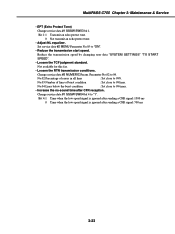
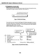
... 1 0 0 Service error code Output Not Output 1 Error dump list Output Not Output 2 Not used 3 Copy function No Yes 4 ##300 series service error code Output Not Output 5 Not used 6 Not used 7 User setting restriction Setting possible Setting restricted Figure 3-25 How to see effective bits and their default values. Bit 7 Bit 6 Bit 5 Bit 4 Bit 3 Bit 2 Bit 1 Bit 0 SW01 0 0 0 0 0 0 0 0 Figure 3-24 Bit Switch Display See the chart in the service data shown in this manual except the new switches added to which numbers are...
... 1 0 0 Service error code Output Not Output 1 Error dump list Output Not Output 2 Not used 3 Copy function No Yes 4 ##300 series service error code Output Not Output 5 Not used 6 Not used 7 User setting restriction Setting possible Setting restricted Figure 3-25 How to see effective bits and their default values. Bit 7 Bit 6 Bit 5 Bit 4 Bit 3 Bit 2 Bit 1 Bit 0 SW01 0 0 0 0 0 0 0 0 Figure 3-24 Bit Switch Display See the chart in the service data shown in this manual except the new switches added to which numbers are...
Service Manual
Page 104
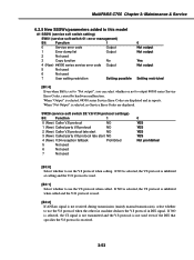
... [Bit 2] If ANSam signal is selected, ##300 series Service Error Codes are displayed. MultiPASS C755 Chapter 3: Maintenance & Service 6.2.5 New SSSWs/parameters added to this model #1 SSSW (service soft switch setting) SW01 (service soft switch 01: error management) Bit Function 1 0 Service error code Output 1 Error dump list Output 2 Not used 3 Copy function No 4 (New) ##300 series service error code Output 5 Not used 6 Not used 7 User setting restriction Setting possible 0 Not output Not output Yes Not output Setting restricted [Bit 4] Even when Bit0 is received...
... [Bit 2] If ANSam signal is selected, ##300 series Service Error Codes are displayed. MultiPASS C755 Chapter 3: Maintenance & Service 6.2.5 New SSSWs/parameters added to this model #1 SSSW (service soft switch setting) SW01 (service soft switch 01: error management) Bit Function 1 0 Service error code Output 1 Error dump list Output 2 Not used 3 Copy function No 4 (New) ##300 series service error code Output 5 Not used 6 Not used 7 User setting restriction Setting possible 0 Not output Not output Yes Not output Setting restricted [Bit 4] Even when Bit0 is received...


