Setup Manual
Page 2
Table of Contents Chapter 1: Introduction 1 1.1 Before You Start 1 1.2 Package Checklist 1 1.3 Motherboard Features 2 1.4 Rear Panel Connectors (for Ver 5.x 4 1.5 Rear Panel Connectors (for Ver 6.x 4 1.6 Motherboard Layout 5 Chapter 2: Hardware Installation 6 2.1 Installing Central Processing Unit (CPU 6 2.2 FAN Headers 8 2.3 Installing System Memory 9 2.4 Connectors and Slots 11 Chapter 3: Headers & Jumpers Setup 13 3.1 How to ...
Table of Contents Chapter 1: Introduction 1 1.1 Before You Start 1 1.2 Package Checklist 1 1.3 Motherboard Features 2 1.4 Rear Panel Connectors (for Ver 5.x 4 1.5 Rear Panel Connectors (for Ver 6.x 4 1.6 Motherboard Layout 5 Chapter 2: Hardware Installation 6 2.1 Installing Central Processing Unit (CPU 6 2.2 FAN Headers 8 2.3 Installing System Memory 9 2.4 Connectors and Slots 11 Chapter 3: Headers & Jumpers Setup 13 3.1 How to ...
Setup Manual
Page 3
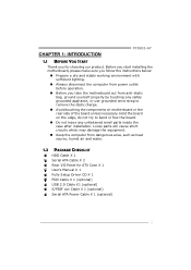
..., or use grounded wrist strap to remove the static charge. „ Avoid touching the components on motherboard or the rear side of the board unless necessary. CHAPTER 1: INTRODUCTION TP35D2-A7 1.1 BEFORE YOU START Thank you take the motherboard out from dangerous area, such as heat source, humid air and water. 1.2 PACKAGE CHECKLIST HDD Cable...
..., or use grounded wrist strap to remove the static charge. „ Avoid touching the components on motherboard or the rear side of the board unless necessary. CHAPTER 1: INTRODUCTION TP35D2-A7 1.1 BEFORE YOU START Thank you take the motherboard out from dangerous area, such as heat source, humid air and water. 1.2 PACKAGE CHECKLIST HDD Cable...
Setup Manual
Page 4
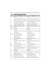
SATA Version 2.0 specification compliant SATA Version 2.0 specification compliant 2 Motherboard Manual 1.3 MOTHERBOARD FEATURES Ver 5.x Ver 6.x LGA 775 LGA 775 Intel Core2Duo / Core2Quad / Celeron 4xx / Intel Core2Duo / Core2Quad / Celeron 4xx / Pentium D / Pentium 4 / Celeron D processor Pentium D / Pentium 4 / Celeron D processor ...
SATA Version 2.0 specification compliant SATA Version 2.0 specification compliant 2 Motherboard Manual 1.3 MOTHERBOARD FEATURES Ver 5.x Ver 6.x LGA 775 LGA 775 Intel Core2Duo / Core2Quad / Celeron 4xx / Intel Core2Duo / Core2Quad / Celeron 4xx / Pentium D / Pentium 4 / Celeron D processor Pentium D / Pentium 4 / Celeron D processor ...
Setup Manual
Page 6
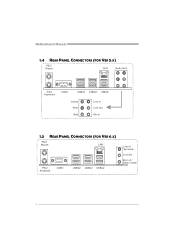
Motherboard Manual 1.4 REAR PANEL CONNECTORS (FOR VER 5.X) PS/2 M ou se LA N Audio Jack PS/ 2 Ke ybo ar d COM1 USBX2 USBX2 USBX2 Center Rear Si de Line In Line Out Mic In 1.5 REAR PANEL CONNECTORS (FOR VER 6.X) PS/2 M ou se LAN PS/ 2 Ke ybo ar d COM1 USBX2 USBX2 USBX2 Line In/ Su rr oun d Line Out Mic In 1/ Bass/ Center 4
Motherboard Manual 1.4 REAR PANEL CONNECTORS (FOR VER 5.X) PS/2 M ou se LA N Audio Jack PS/ 2 Ke ybo ar d COM1 USBX2 USBX2 USBX2 Center Rear Si de Line In Line Out Mic In 1.5 REAR PANEL CONNECTORS (FOR VER 6.X) PS/2 M ou se LAN PS/ 2 Ke ybo ar d COM1 USBX2 USBX2 USBX2 Line In/ Su rr oun d Line Out Mic In 1/ Bass/ Center 4
Setup Manual
Page 7
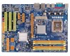
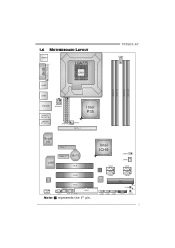
1.6 MOTHERBOARD LAYOUT JKBMS1 JPRNT1 LGA775 CPU1 TP35D2-A7 JCFAN1 JCOM1 JUSB2 DDR2_A1 DDR2_A2 DDR2_B1 DDR2_B2 JUSB1 JRJ45USB1 JATXPWR1 JAUDIO1 (for Ver 5.x) JAUDIO2 (for Ver 6.x) JATXPWR2 JNFAN1 PEX16_1 Intel P35 Super I/O PEX4_1 LAN PEX1_1 BAT1 PCI1 PCI2 CODEC PCI3 JSPDIF_OUT1 FDD1 JAUDIOF1 JCDIN1 JSPDI F_IN1 (optional) Note: ■ represents the 1st pin. Intel ICH9 JCMOS1 JSFAN1 BIOS SATA3 SATA1 SATA4 SATA2 IDE IDE1 JUSB5 JUSB4 JUSB3 RSTSW2 LED2 LE D1 J PANEL1 PWRSW1 5
1.6 MOTHERBOARD LAYOUT JKBMS1 JPRNT1 LGA775 CPU1 TP35D2-A7 JCFAN1 JCOM1 JUSB2 DDR2_A1 DDR2_A2 DDR2_B1 DDR2_B2 JUSB1 JRJ45USB1 JATXPWR1 JAUDIO1 (for Ver 5.x) JAUDIO2 (for Ver 6.x) JATXPWR2 JNFAN1 PEX16_1 Intel P35 Super I/O PEX4_1 LAN PEX1_1 BAT1 PCI1 PCI2 CODEC PCI3 JSPDIF_OUT1 FDD1 JAUDIOF1 JCDIN1 JSPDI F_IN1 (optional) Note: ■ represents the 1st pin. Intel ICH9 JCMOS1 JSFAN1 BIOS SATA3 SATA1 SATA4 SATA2 IDE IDE1 JUSB5 JUSB4 JUSB3 RSTSW2 LED2 LE D1 J PANEL1 PWRSW1 5
Setup Manual
Page 8
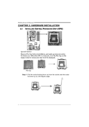
When the CPU is removed, cover the Pin Cap on the empty socket to a 90-degree angle. 6 Pin Cap Step 1: Pull the socket locking lever out from the socket and then raise the lever up to ensure pin legs won't be damaged. Motherboard Manual CHAPTER 2: HARDWARE INSTALLATION 2.1 INSTALLING CENTRAL PROCESSING UNIT (CPU) Special Notice: Remove Pin Cap before installation, and make good preservation for future use.
When the CPU is removed, cover the Pin Cap on the empty socket to a 90-degree angle. 6 Pin Cap Step 1: Pull the socket locking lever out from the socket and then raise the lever up to ensure pin legs won't be damaged. Motherboard Manual CHAPTER 2: HARDWARE INSTALLATION 2.1 INSTALLING CENTRAL PROCESSING UNIT (CPU) Special Notice: Remove Pin Cap before installation, and make good preservation for future use.
Setup Manual
Page 10
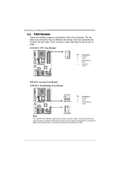
... Header JNFAN1: Northbridge Fan Header 13 JNFAN1 Pin Assignment 1 Ground 2 +12V 3 FAN RPM rate sense 1 3 JSFAN1 Note: The JNFAN1 and JSFAN1 support 3-pin head connector. Motherboard Manual 2.2 FAN HEADERS These fan headers support cooling-fans built in the computer.
... Header JNFAN1: Northbridge Fan Header 13 JNFAN1 Pin Assignment 1 Ground 2 +12V 3 FAN RPM rate sense 1 3 JSFAN1 Note: The JNFAN1 and JSFAN1 support 3-pin head connector. Motherboard Manual 2.2 FAN HEADERS These fan headers support cooling-fans built in the computer.
Setup Manual
Page 12
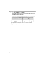
Dual Channel Status DDR2_A1 DDR2_A2 DDR2_B1 DDR2_B2 Enabled O X O X Enabled X O X O Enabled O O O O (O means memory installed, X means memory not installed.) The DRAM bus width of the memory module must meet the following requirements: Install memory module of the motherboard, the memory module must be the same (x8 or x16) 10 Dual Channel Memory installation To trigger the Dual Channel function of the same density in pairs, shown in the following table. Motherboard Manual C.
Dual Channel Status DDR2_A1 DDR2_A2 DDR2_B1 DDR2_B2 Enabled O X O X Enabled X O X O Enabled O O O O (O means memory installed, X means memory not installed.) The DRAM bus width of the memory module must meet the following requirements: Install memory module of the motherboard, the memory module must be the same (x8 or x16) 10 Dual Channel Memory installation To trigger the Dual Channel function of the same density in pairs, shown in the following table. Motherboard Manual C.
Setup Manual
Page 13
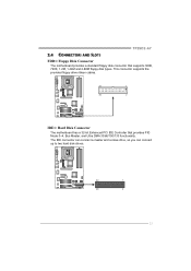
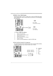
This connector supports the provided floppy drive ribbon cables. 33 1 34 2 IDE1: Hard Disk Connector The motherboard has a 32-bit Enhanced PCI IDE Controller that supports 360K, 720K, 1.2M, 1.44M and 2.88M floppy disk types. The IDE connector can connect a master and a slave drive, so you can connect up to two hard disk drives. 39 1 40 2 11 TP35D2-A7 2.4 CONNECTORS AND SLOTS FDD1: Floppy Disk Connector The motherboard provides a standard floppy disk connector that provides PIO Mode 0~4, Bus Master, and Ultra DMA 33/66/100/133 functionality.
This connector supports the provided floppy drive ribbon cables. 33 1 34 2 IDE1: Hard Disk Connector The motherboard has a 32-bit Enhanced PCI IDE Controller that supports 360K, 720K, 1.2M, 1.44M and 2.88M floppy disk types. The IDE connector can connect a master and a slave drive, so you can connect up to two hard disk drives. 39 1 40 2 11 TP35D2-A7 2.4 CONNECTORS AND SLOTS FDD1: Floppy Disk Connector The motherboard provides a standard floppy disk connector that provides PIO Mode 0~4, Bus Master, and Ultra DMA 33/66/100/133 functionality.
Setup Manual
Page 14
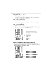
PCI-Express 1.0a compliant. - PEX4_1: PCI-Express x4 Slot - PEX16_1 PEX4_1 PEX1_1 PCI1~PCI3: Peripheral Component Interconnect Slots This motherboard is designated as 32 bits. PCI1 PCI2 PCI3 12 Motherboard Manual PEX16_1: PCI-Express x16 Slot - Maximum theoretical realized bandwidth of 250MB/s simultaneously per direction, for an aggregate of 4GB/s simultaneously per direction...
PCI-Express 1.0a compliant. - PEX4_1: PCI-Express x4 Slot - PEX16_1 PEX4_1 PEX1_1 PCI1~PCI3: Peripheral Component Interconnect Slots This motherboard is designated as 32 bits. PCI1 PCI2 PCI3 12 Motherboard Manual PEX16_1: PCI-Express x16 Slot - Maximum theoretical realized bandwidth of 250MB/s simultaneously per direction, for an aggregate of 4GB/s simultaneously per direction...
Setup Manual
Page 16
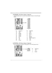
Motherboard Manual JATXPWR2: ATX Power Source Connector JATXPW2 allows user to connect 24-pin power connector on the ATX power supply. 13 1 Pin Assignment 13 +3.3V ...
Motherboard Manual JATXPWR2: ATX Power Source Connector JATXPW2 allows user to connect 24-pin power connector on the ATX power supply. 13 1 Pin Assignment 13 +3.3V ...
Setup Manual
Page 18
... 4. Set the jumper to "Pin 2-3 close ". 5. Reset your desired password or clear the CMOS data. SATA1~SATA4: Serial ATA Connectors The motherboard has a PCI to SATA Controller with 4 channels SATA interface, it allows user to restore the BIOS safe setting and the CMOS data, please carefully ... 3. SATA3 SATA1 SATA4 SATA2 741 Pin Assignment 1 Ground 2 TX+ 3 TX4 Ground 5 RX6 RX+ 7 Ground 16 Set the jumper to avoid damaging the motherboard. 3 1 Pin 1-2 Close: Normal Operation (default). 3 1 3 1 Pin 2-3 Close: Clear CMOS data. ※ Clear CMOS Procedures: 1. Remove AC power line...
... 4. Set the jumper to "Pin 2-3 close ". 5. Reset your desired password or clear the CMOS data. SATA1~SATA4: Serial ATA Connectors The motherboard has a PCI to SATA Controller with 4 channels SATA interface, it allows user to restore the BIOS safe setting and the CMOS data, please carefully ... 3. SATA3 SATA1 SATA4 SATA2 741 Pin Assignment 1 Ground 2 TX+ 3 TX4 Ground 5 RX6 RX+ 7 Ground 16 Set the jumper to avoid damaging the motherboard. 3 1 Pin 1-2 Close: Normal Operation (default). 3 1 3 1 Pin 2-3 Close: Clear CMOS data. ※ Clear CMOS Procedures: 1. Remove AC power line...
Setup Manual
Page 20
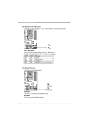
RSTSW2 PWRSW1 PWRSW1: This is an on -board Power Switch button. Please refer to show system status. RSTSW2: This is an on -board Reset button. 18 LED2 LED1 and LED2: LED1 These 2 LED indicate system power on diagnostics. On-Board Buttons There are 2 LED indicators on the motherboard to the table below for different messages: LED1 LED2 Message ON ON Normal ON OFF Memory Error OFF ON VGA Error OFF OFF Abnormal: CPU / Chipset error. Motherboard Manual On-Board LED Indicators There are 2 on-board buttons.
RSTSW2 PWRSW1 PWRSW1: This is an on -board Power Switch button. Please refer to show system status. RSTSW2: This is an on -board Reset button. 18 LED2 LED1 and LED2: LED1 These 2 LED indicate system power on diagnostics. On-Board Buttons There are 2 LED indicators on the motherboard to the table below for different messages: LED1 LED2 Message ON ON Normal ON OFF Memory Error OFF ON VGA Error OFF OFF Abnormal: CPU / Chipset error. Motherboard Manual On-Board LED Indicators There are 2 on-board buttons.
Setup Manual
Page 22
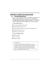
.... WARNING !! Based on board may be different from this manual. For better system performance, the BIOS firmware is being continuously updated. Motherboard Manual CHAPTER 4: OVERCLOCK QUICK GUIDE 4.1 T-POWER INTRODUCTION Biostar T-Power is a whole new utility that is designed for your reference only and the actual BIOS information and settings on many precise...
.... WARNING !! Based on board may be different from this manual. For better system performance, the BIOS firmware is being continuously updated. Motherboard Manual CHAPTER 4: OVERCLOCK QUICK GUIDE 4.1 T-POWER INTRODUCTION Biostar T-Power is a whole new utility that is designed for your reference only and the actual BIOS information and settings on many precise...
Setup Manual
Page 24
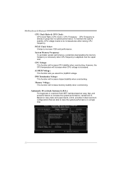
... you select the (G)MCH voltage. Memory Voltage: This function will increase CPU stability when overclocking. However, the CPU temperature will increase chipset stability when overclocking. Motherboard Manual CPU Clock Ratio & CPU Clock: CPU Clock Ratio x CPU Clock = CPU Frequency. PCI-E Clock Select: It helps to be increased also when raising CPU...
... you select the (G)MCH voltage. Memory Voltage: This function will increase CPU stability when overclocking. However, the CPU temperature will increase chipset stability when overclocking. Motherboard Manual CPU Clock Ratio & CPU Clock: CPU Clock Ratio x CPU Clock = CPU Frequency. PCI-E Clock Select: It helps to be increased also when raising CPU...
Setup Manual
Page 26
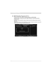
Users are able to personal preference. 24 There are 50 sets of record addresses in total, and users are able to save an ideal overclock setting during overclock operation. CMOS Reloading Program (C.R.P.): It allows users to save different CMOS settings into BIOS-ROM. Moreover, users are able to name the CMOS data according to reload any saved CMOS setting for customizing system configurations. Motherboard Manual B.
Users are able to personal preference. 24 There are 50 sets of record addresses in total, and users are able to save an ideal overclock setting during overclock operation. CMOS Reloading Program (C.R.P.): It allows users to save different CMOS settings into BIOS-ROM. Moreover, users are able to name the CMOS data according to reload any saved CMOS setting for customizing system configurations. Motherboard Manual B.
Setup Manual
Page 28
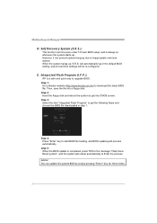
... item "Integrated Flash Program" to upgrade BIOS. Step 5: When the BIOS update is always on whenever the system starts up , S.R.S. Step 1: Go to Biostar website (http://www.biostar.com.tw) to inappropriate overclock actions. Advise: You can prevent system hang-up due to download the latest BIOS file. Self Recovery System (S.R.S.): This...
... item "Integrated Flash Program" to upgrade BIOS. Step 5: When the BIOS update is always on whenever the system starts up , S.R.S. Step 1: Go to Biostar website (http://www.biostar.com.tw) to inappropriate overclock actions. Advise: You can prevent system hang-up due to download the latest BIOS file. Self Recovery System (S.R.S.): This...
Setup Manual
Page 30
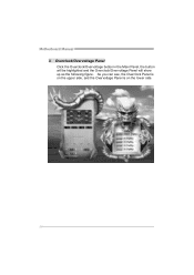
Overclock/Overvoltage Panel Click the Overclock/Overvoltage button in the Main Panel, the button will be highlighted and the Overclock/Overvoltage Panel will show up as the following figure. Motherboard Manual 3. As you can see, the Overclock Panel is on the upper side, and the Overvoltage Panel is on the lower side. 28
Overclock/Overvoltage Panel Click the Overclock/Overvoltage button in the Main Panel, the button will be highlighted and the Overclock/Overvoltage Panel will show up as the following figure. Motherboard Manual 3. As you can see, the Overclock Panel is on the upper side, and the Overvoltage Panel is on the lower side. 28
Setup Manual
Page 32
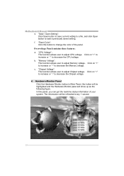
... button in Main Panel, the button will show up as the following figure. Overvoltage Panel contains these features: a. In this button to adjust Chipset voltage. Motherboard Manual e. The information will be highlighted and the Hardware Monitor panel will be refreshed every 1 second. 30 "Save / Open Setting": Click Save button to save...
... button in Main Panel, the button will show up as the following figure. Overvoltage Panel contains these features: a. In this button to adjust Chipset voltage. Motherboard Manual e. The information will be highlighted and the Hardware Monitor panel will be refreshed every 1 second. 30 "Save / Open Setting": Click Save button to save...
Setup Manual
Page 34
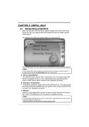
...system, please insert the Fully Setup Driver CD into your optical drive and install the driver for your motherboard and operating system. A. Click on each software title to launch the installation program. Motherboard Manual CHAPTER 5: USEFUL HELP 5.1 DRIVER INSTALLATION NOTE After you insert the CD The setup guide will... auto detect your motherboard and operating system. Click on the Manual icon to launch the installation program. The setup guide will need Acrobat Reader to ...
...system, please insert the Fully Setup Driver CD into your optical drive and install the driver for your motherboard and operating system. A. Click on each software title to launch the installation program. Motherboard Manual CHAPTER 5: USEFUL HELP 5.1 DRIVER INSTALLATION NOTE After you insert the CD The setup guide will... auto detect your motherboard and operating system. Click on the Manual icon to launch the installation program. The setup guide will need Acrobat Reader to ...

