Setup Manual
Page 2
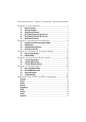
... Panel Connectors (for Ver 6.x 4 1.6 Motherboard Layout 5 Chapter 2: Hardware Installation 6 2.1 Installing Central Processing Unit (CPU 6 2.2 FAN Headers 8 2.3 Installing System Memory 9 2.4 Connectors and Slots 11 Chapter 3: Headers & Jumpers Setup 13 3.1 How to Setup Jumpers 13 3.2 Detail Settings 13 Chapter 4: OverClock Quick Guide 20 4.1 T-Power Introduction 20 4.2 T-Power BIOS Feature 20 4.3 T-Power Windows Feature 26 Chapter 5: Useful Help 32 5.1 Driver Installation Note 32 5.2 Award BIOS Beep Code 33 5.3 Extra Information 33 5.4 Troubleshooting 35 Appendencies: SPEC...
... Panel Connectors (for Ver 6.x 4 1.6 Motherboard Layout 5 Chapter 2: Hardware Installation 6 2.1 Installing Central Processing Unit (CPU 6 2.2 FAN Headers 8 2.3 Installing System Memory 9 2.4 Connectors and Slots 11 Chapter 3: Headers & Jumpers Setup 13 3.1 How to Setup Jumpers 13 3.2 Detail Settings 13 Chapter 4: OverClock Quick Guide 20 4.1 T-Power Introduction 20 4.2 T-Power BIOS Feature 20 4.3 T-Power Windows Feature 26 Chapter 5: Useful Help 32 5.1 Driver Installation Note 32 5.2 Award BIOS Beep Code 33 5.3 Extra Information 33 5.4 Troubleshooting 35 Appendencies: SPEC...
Setup Manual
Page 3
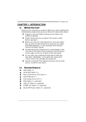
... HDD Cable X 1 Serial ATA Cable X 2 Rear I/O Panel for choosing our product. Before you start installing the motherboard, please make sure you follow the instructions below: „ Prepare a dry and stable working environment with sufficient lighting. „ Always disconnect the computer from power outlet before operation. „ Before you for ATX Case X 1 User's Manual X 1 Fully Setup Driver CD X 1 FDD Cable X 1 (optional) USB 2.0 Cable X1 (optional) S/PDIF out Cable X 1 (optional) Serial ATA Power Cable X 1 (optional) 1 CHAPTER 1: INTRODUCTION TP35D2-A7 1.1 BEFORE YOU START...
... HDD Cable X 1 Serial ATA Cable X 2 Rear I/O Panel for choosing our product. Before you start installing the motherboard, please make sure you follow the instructions below: „ Prepare a dry and stable working environment with sufficient lighting. „ Always disconnect the computer from power outlet before operation. „ Before you for ATX Case X 1 User's Manual X 1 Fully Setup Driver CD X 1 FDD Cable X 1 (optional) USB 2.0 Cable X1 (optional) S/PDIF out Cable X 1 (optional) Serial ATA Power Cable X 1 (optional) 1 CHAPTER 1: INTRODUCTION TP35D2-A7 1.1 BEFORE YOU START...
Setup Manual
Page 5
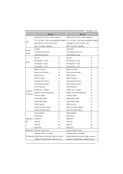
... connector x1 S/PDIF in connector(optional) x1 CPU Fan header x1 System Fan header x2 Clear CMOS header x1 USB connector x3 Power Connector (24pin) x1 Power Connector (4pin) x1 PS/2 Keyboard x1 PS/2 Keyboard x1 PS/2 Mouse x1 PS/2 Mouse x1 Back Panel Serial Port x1 Serial Port x1 I/O LAN port x1 LAN port x1 USB Port x6 USB Port x6 Audio Jack x6 Audio Jack x3 Board Size 220 (W) x 305 (L) mm 220 (W) x 305 (L) mm Windows 2000 / XP / VISTA OS Support Biostar Reserves the right to add or remove support...
... connector x1 S/PDIF in connector(optional) x1 CPU Fan header x1 System Fan header x2 Clear CMOS header x1 USB connector x3 Power Connector (24pin) x1 Power Connector (4pin) x1 PS/2 Keyboard x1 PS/2 Keyboard x1 PS/2 Mouse x1 PS/2 Mouse x1 Back Panel Serial Port x1 Serial Port x1 I/O LAN port x1 LAN port x1 USB Port x6 USB Port x6 Audio Jack x6 Audio Jack x3 Board Size 220 (W) x 305 (L) mm 220 (W) x 305 (L) mm Windows 2000 / XP / VISTA OS Support Biostar Reserves the right to add or remove support...
Setup Manual
Page 13
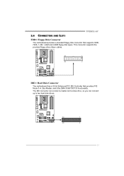
TP35D2-A7 2.4 CONNECTORS AND SLOTS FDD1: Floppy Disk Connector The motherboard provides a standard floppy disk connector that provides PIO Mode 0~4, Bus Master, and Ultra DMA 33/66/100/133 functionality. The IDE connector can connect a master and a slave drive, so you can connect up to two hard disk drives. 39 1 40 2 11 This connector supports the provided floppy drive ribbon cables. 33 1 34 2 IDE1: Hard Disk Connector The motherboard has a 32-bit Enhanced PCI IDE Controller that supports 360K, 720K, 1.2M, 1.44M and 2.88M floppy disk types.
TP35D2-A7 2.4 CONNECTORS AND SLOTS FDD1: Floppy Disk Connector The motherboard provides a standard floppy disk connector that provides PIO Mode 0~4, Bus Master, and Ultra DMA 33/66/100/133 functionality. The IDE connector can connect a master and a slave drive, so you can connect up to two hard disk drives. 39 1 40 2 11 This connector supports the provided floppy drive ribbon cables. 33 1 34 2 IDE1: Hard Disk Connector The motherboard has a 32-bit Enhanced PCI IDE Controller that supports 360K, 720K, 1.2M, 1.44M and 2.88M floppy disk types.

Setup Manual
Page 15
... 12 Hard drive 13 LED 14 Reset button 15 16 Assignment Sleep control Ground N/A Power LED (+) Power LED (+) Power LED (-) Power button Ground Function Sleep button N/A Power LED Power-on , Reset, HDD LED, Power LED, Sleep button and speaker connection. Pin opened Pin closed Pin1-2 closed 3.2 DETAIL SETTINGS JPANEL1: Front Panel Header This 16-pin connector includes Power-on button 13 When the jumper cap is placed on pins, the jumper is "close", if not, that means the jumper is "open". It allows user to set up jumpers. TP35D2-A7 CHAPTER 3: HEADERS & JUMPERS SETUP 3.1 HOW...
... 12 Hard drive 13 LED 14 Reset button 15 16 Assignment Sleep control Ground N/A Power LED (+) Power LED (+) Power LED (-) Power button Ground Function Sleep button N/A Power LED Power-on , Reset, HDD LED, Power LED, Sleep button and speaker connection. Pin opened Pin closed Pin1-2 closed 3.2 DETAIL SETTINGS JPANEL1: Front Panel Header This 16-pin connector includes Power-on button 13 When the jumper cap is placed on pins, the jumper is "close", if not, that means the jumper is "open". It allows user to set up jumpers. TP35D2-A7 CHAPTER 3: HEADERS & JUMPERS SETUP 3.1 HOW...
Setup Manual
Page 27
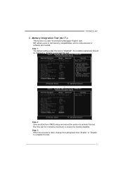
... default setting under this test. ↓ Step 2: Save and Exit from "Enable" to "Disable" to proceed this item is under "Overclocking Navigator Engine" item. Memory Integration Test (M.I.T.): This function is "Disabled"; Step 3: When the process is done, change the setting back from CMOS setup and reboot the system to activate this test for 5 minutes (minimum) to test memory compatibilities, and no extra devices or software...
... default setting under this test. ↓ Step 2: Save and Exit from "Enable" to "Disable" to proceed this item is under "Overclocking Navigator Engine" item. Memory Integration Test (M.I.T.): This function is "Disabled"; Step 3: When the process is done, change the setting back from CMOS setup and reboot the system to activate this test for 5 minutes (minimum) to test memory compatibilities, and no extra devices or software...
Setup Manual
Page 32
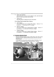
... or "-" to adjust Chipset voltage. Click on "+" to increase or "-" to decrease the Memory voltage. "Chipset Voltage": This function allows user to decrease the CPU voltage. In this button to load a previously saved setting. "Save / Open Setting": Click Save button to save current setting to a file, and click Open button to change the color of your system. The information will be highlighted and the Hardware Monitor panel will be refreshed...
... or "-" to adjust Chipset voltage. Click on "+" to increase or "-" to decrease the Memory voltage. "Chipset Voltage": This function allows user to decrease the CPU voltage. In this button to load a previously saved setting. "Save / Open Setting": Click Save button to save current setting to a file, and click Open button to change the color of your system. The information will be highlighted and the Hardware Monitor panel will be refreshed...
Setup Manual
Page 35
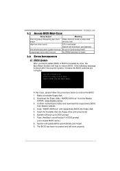
... BIOS: 1. TP35D2-A7 5.2 AWARD BIOS BEEP CODE Beep Sound Meaning One long beep followed by virus, the Boot-Block function will help to restore BIOS. Insert the bootable disk into floppy disk. 5. System will work properly. 33 BIOS Update After you fail to update BIOS or BIOS is shown after boot-up No error found during POST Long beeps every other second No DRAM detected or install 5.3 EXTRA INFORMATION A. Copy "AWDFLASH.exe" and respectively BIOS into floppy drive and press Enter. 6. Confirm motherboard model and download...
... BIOS: 1. TP35D2-A7 5.2 AWARD BIOS BEEP CODE Beep Sound Meaning One long beep followed by virus, the Boot-Block function will help to restore BIOS. Insert the bootable disk into floppy disk. 5. System will work properly. 33 BIOS Update After you fail to update BIOS or BIOS is shown after boot-up No error found during POST Long beeps every other second No DRAM detected or install 5.3 EXTRA INFORMATION A. Copy "AWDFLASH.exe" and respectively BIOS into floppy drive and press Enter. 6. Confirm motherboard model and download...
Setup Manual
Page 37
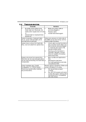
...the drive type in setup. No power to disk controller board. Screen message says "Invalid Configuration" or "CMOS Failure." drive, can be booted from optical drive. 1. Call the drive manufacturers for compatibility with other drives. 35 System only boots from optical drive. 2. Review system's equipment. Make sure correct information is Power light don't illuminate, fan securely plugged in ; TP35D2-A7 5.4 TROUBLESHOOTING Probable Solution 1. Indicator light on . 3. Hard disk can be read and applications can be used but booting from hard disk 2. on keyboard...
...the drive type in setup. No power to disk controller board. Screen message says "Invalid Configuration" or "CMOS Failure." drive, can be booted from optical drive. 1. Call the drive manufacturers for compatibility with other drives. 35 System only boots from optical drive. 2. Review system's equipment. Make sure correct information is Power light don't illuminate, fan securely plugged in ; TP35D2-A7 5.4 TROUBLESHOOTING Probable Solution 1. Indicator light on . 3. Hard disk can be read and applications can be used but booting from hard disk 2. on keyboard...
Setup Manual
Page 57
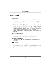
..., such as keyboard, mouse, serial ports and disk drives. BIOS activates at the first stage of the EPA Green PC spec ification. The rest of CMOS RAM is supplied by this PHOENIX-AW ARD BIOS. 1 The power of this manual will to guide you through the options and settings in the Phoenix-Award™ BIOS Setup program on this manual is turned off. APM Support This PHOENIX-AWARD BIOS supports Version 1.1&1.2 of this motherboard. TP35D2-A7 BIOS Setup Introduction The purpose...
..., such as keyboard, mouse, serial ports and disk drives. BIOS activates at the first stage of the EPA Green PC spec ification. The rest of CMOS RAM is supplied by this PHOENIX-AW ARD BIOS. 1 The power of this manual will to guide you through the options and settings in the Phoenix-Award™ BIOS Setup program on this manual is turned off. APM Support This PHOENIX-AWARD BIOS supports Version 1.1&1.2 of this motherboard. TP35D2-A7 BIOS Setup Introduction The purpose...
Setup Manual
Page 62
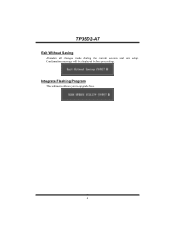
TP35D2-A7 Exit Without Saving Abandon all changes made during the current session and exit setup. Confirmation message will be displayed before proceeding. Integrate Flashing Program This submenu allows you to upgrade bios. 6
TP35D2-A7 Exit Without Saving Abandon all changes made during the current session and exit setup. Confirmation message will be displayed before proceeding. Integrate Flashing Program This submenu allows you to upgrade bios. 6
Setup Manual
Page 67
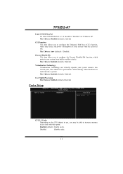
... Choices: Enabled (default), Disabled. TP35D2-A7 Limit CPUID MaxVal Set Limit CPUID MaxVal to increase memory access time with this option. Cache Setup CPU L3 Cache Depending on the CPU/chipset in use, you to configure the Execute Disabled Bit function, which may be able to 3, it should be "Disabled" for Windows XP. The Choices: Enabled (default), Disabled. The Choices: Auto (default),Disabled. C1E Function This item allows you may reduce the power consumption of...
... Choices: Enabled (default), Disabled. TP35D2-A7 Limit CPUID MaxVal Set Limit CPUID MaxVal to increase memory access time with this option. Cache Setup CPU L3 Cache Depending on the CPU/chipset in use, you to configure the Execute Disabled Bit function, which may be able to 3, it should be "Disabled" for Windows XP. The Choices: Enabled (default), Disabled. The Choices: Auto (default),Disabled. C1E Function This item allows you may reduce the power consumption of...
Setup Manual
Page 69
...: Enabled (default), Disabled. The Choices: Floppy, LS120, Hard Disk, CDROM, ZIP100, USB-FDD, USB-ZIP, USB-CDROM, LAN, Disabled. Hyper-Threading Technology This option allows you to load the operating system from the three devices above. Boot Other Device When enabled, BIOS will test the floppy drives to determine if they have 40 or 80 tracks during boot up. If this order. TP35D2-A7 First/Second/Third Boot Device The BIOS will cause an abridged version of the Power...
...: Enabled (default), Disabled. The Choices: Floppy, LS120, Hard Disk, CDROM, ZIP100, USB-FDD, USB-ZIP, USB-CDROM, LAN, Disabled. Hyper-Threading Technology This option allows you to load the operating system from the three devices above. Boot Other Device When enabled, BIOS will test the floppy drives to determine if they have 40 or 80 tracks during boot up. If this order. TP35D2-A7 First/Second/Third Boot Device The BIOS will cause an abridged version of the Power...

Setup Manual
Page 70
... hold the key down before it begins to use the CMOS Setup Utility. The Choices: Disabled (default), Enabled. Typematic Delay (Msec) Sets the delay time after the system switched on. Security Option This option will only apply if passwords are set from the Setup main menu. 14 Gate A20 Option Select if chipset or keyboard controller should control Gate A20. Off Numpad is number keys. The Choices: On (default) Numpad is arrow keys. TP35D2-A7 Boot Up NumLock...
... hold the key down before it begins to use the CMOS Setup Utility. The Choices: Disabled (default), Enabled. Typematic Delay (Msec) Sets the delay time after the system switched on. Security Option This option will only apply if passwords are set from the Setup main menu. 14 Gate A20 Option Select if chipset or keyboard controller should control Gate A20. Off Numpad is number keys. The Choices: On (default) Numpad is arrow keys. TP35D2-A7 Boot Up NumLock...
Setup Manual
Page 71
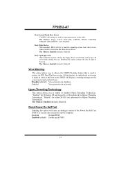
... multiprocessor specification. OS Select For DRAM > 64MB A choice other than Non-OS2 is only used for OS2 systems with memory exceeding 64MB. TP35D2-A7 APIC MODE Selecting Enabled enables APIC device mode reporting from the BIOS to enable/disable the summary screen. Select version supported by the operation system running on this computer. Summary Screen Show This item allows you to the operating system. Summary screen means system configuration and PCI device listing.
... multiprocessor specification. OS Select For DRAM > 64MB A choice other than Non-OS2 is only used for OS2 systems with memory exceeding 64MB. TP35D2-A7 APIC MODE Selecting Enabled enables APIC device mode reporting from the BIOS to enable/disable the summary screen. Select version supported by the operation system running on this computer. Summary Screen Show This item allows you to the operating system. Summary screen means system configuration and PCI device listing.
Setup Manual
Page 72
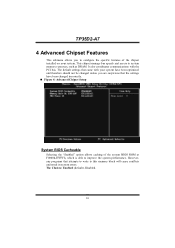
... chipset manage bus speeds and access to this memory block will cause conflicts and result in system errors. However, any programs that the settings have been optimized and therefore should not be changed incorrectly. „ Figure 4: Advanced Chipset Setup System BIOS Cacheable Selecting the "Enabled" option allows caching of the chipset installed on your system have been changed unless you to configure the specific features of the system BIOS ROM...
... chipset manage bus speeds and access to this memory block will cause conflicts and result in system errors. However, any programs that the settings have been optimized and therefore should not be changed incorrectly. „ Figure 4: Advanced Chipset Setup System BIOS Cacheable Selecting the "Enabled" option allows caching of the chipset installed on your system have been changed unless you to configure the specific features of the system BIOS ROM...
Setup Manual
Page 75
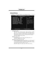
TP35D2-A7 OnChip IDE Device Highlight the "Press Enter" label next to enable or disable the IDE DMA transfer access. IDE DMA Transfer Access This item allows you a submenu with the following options: IDE HDD Block Mode Block mode is also called block transfer, multiple commands, or multiple sectors read / write per sector where the drive can support. Modes 0 to 4 will take you to the "OnChip IDE Device" label and press enter key will...
TP35D2-A7 OnChip IDE Device Highlight the "Press Enter" label next to enable or disable the IDE DMA transfer access. IDE DMA Transfer Access This item allows you a submenu with the following options: IDE HDD Block Mode Block mode is also called block transfer, multiple commands, or multiple sectors read / write per sector where the drive can support. Modes 0 to 4 will take you to the "OnChip IDE Device" label and press enter key will...

Setup Manual
Page 76
...uses no floppy drive, select disabled in this field. The Choices: Enabled (default), Disabled. If your hard drive and your operating environment requires a DMA driver (Windows 95 or OSR2may need a third party IDE bus master driver). Super IO Device Press Enter to configure the Super I/O Device. Onboard FDC Controller Select enabled if your system. LEGACY Mode Support This item allows you to enable or disable the primary / secondary IDE Channel. The Choices: Enabled (default), Disabled. 20 The Choices: Auto (default), Disabled. The Choices: Disabled (default), Enabled. TP35D2...
...uses no floppy drive, select disabled in this field. The Choices: Enabled (default), Disabled. If your hard drive and your operating environment requires a DMA driver (Windows 95 or OSR2may need a third party IDE bus master driver). Super IO Device Press Enter to configure the Super I/O Device. Onboard FDC Controller Select enabled if your system. LEGACY Mode Support This item allows you to enable or disable the primary / secondary IDE Channel. The Choices: Enabled (default), Disabled. 20 The Choices: Auto (default), Disabled. The Choices: Disabled (default), Enabled. TP35D2...

Setup Manual
Page 78
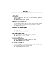
...All of USB device operated on high speed mode. The Choices: High Speed (default), Full/Low Speed. TP35D2-A7 USB Device Setting Highlight the "Press Enter" label next to the "Onboard Device" label and press the enter key will take you to enable/disable Enhanced host controller . Enabled(default) Enable USB Keyboard/ Mouse/ USB Storage Support. The Choices: Enabled (default), Disabled. USB Keyboard/ Mouse/ USB Storage Function This item allows you a submenu with the following options: USB 1.0/2.0 Controller If your system contains a Universal Serial Bus (USB) controller, This...
...All of USB device operated on high speed mode. The Choices: High Speed (default), Full/Low Speed. TP35D2-A7 USB Device Setting Highlight the "Press Enter" label next to the "Onboard Device" label and press the enter key will take you to enable/disable Enhanced host controller . Enabled(default) Enable USB Keyboard/ Mouse/ USB Storage Support. The Choices: Enabled (default), Disabled. USB Keyboard/ Mouse/ USB Storage Function This item allows you a submenu with the following options: USB 1.0/2.0 Controller If your system contains a Universal Serial Bus (USB) controller, This...
Setup Manual
Page 79
PCI-E Compliancy Mode This item allows you to enable or disable the Onboard LAN. Onboard LAN This item allows you to contents of USB MSD decide boot up type. [FDD Mode]: The USB MSD always boot up as floppy disk. [HDD Mode]: The USB MSD always boot up as hard disk. TP35D2-A7 UFDDA/U FDDB The Choices: USB Floppy (default). Onboard LAN Boot ROM This item allows you to PATA IDE cntrlr The Choices: Auto (default), Disabled. The Choices: Auto mode (default), FDD mode, HDD mode. PCIE to enable or disable the Onboard LAN Boot ROM. The Choices: Disabled (default), Enabled. 23...
PCI-E Compliancy Mode This item allows you to enable or disable the Onboard LAN. Onboard LAN This item allows you to contents of USB MSD decide boot up type. [FDD Mode]: The USB MSD always boot up as floppy disk. [HDD Mode]: The USB MSD always boot up as hard disk. TP35D2-A7 UFDDA/U FDDB The Choices: USB Floppy (default). Onboard LAN Boot ROM This item allows you to PATA IDE cntrlr The Choices: Auto (default), Disabled. The Choices: Auto mode (default), FDD mode, HDD mode. PCIE to enable or disable the Onboard LAN Boot ROM. The Choices: Disabled (default), Enabled. 23...


