
TForce 6100 user's manual
Page 2
... ...22 ii User's Manual DDR Installation Notice...3 D. BIOS Update...12 B. About FAN Headers ...2 2.2 SYSTEM MEMORY...2 A. Know your CPU version ...3 2.3 PERIPHERALS ...4 A. Card and I CHAPTER 1: INTRODUCTION ...1 1.1 MOTHERBOARD FEATURES ...1 1.2 LAYOUT AND COMPONENTS: TFORCE 6100-939...2 1.3 LAYOUT AND COMPONENTS: TFORCE 6100 ...3 CHAPTER 2: HARDWARE INSTALLATIONS ...1 2.1 CPU ASSEMBLY ...1 A. DDR Modules ...3 B. Biostar T-Series TForce 6100-939/ TForce 6100 PACKAGE CHECKLIST ...I /O Slots:...4 B. Central Processing Unit (CPU) for Socket 754...1 C.
... ...22 ii User's Manual DDR Installation Notice...3 D. BIOS Update...12 B. About FAN Headers ...2 2.2 SYSTEM MEMORY...2 A. Know your CPU version ...3 2.3 PERIPHERALS ...4 A. Card and I CHAPTER 1: INTRODUCTION ...1 1.1 MOTHERBOARD FEATURES ...1 1.2 LAYOUT AND COMPONENTS: TFORCE 6100-939...2 1.3 LAYOUT AND COMPONENTS: TFORCE 6100 ...3 CHAPTER 2: HARDWARE INSTALLATIONS ...1 2.1 CPU ASSEMBLY ...1 A. DDR Modules ...3 B. Biostar T-Series TForce 6100-939/ TForce 6100 PACKAGE CHECKLIST ...I /O Slots:...4 B. Central Processing Unit (CPU) for Socket 754...1 C.
TForce 6100 user's manual
Page 3
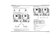
...data transfer rates up to 3Gb/s. One SPDIF-Out connector. Two Ultra DMA 133/100/66/33 IDE connectors. TForce 6100-939/ TForce 6100 Chipset North Bridge: NVIDIA Geforce6100. Supports PIO mode 0~4, Block Mode and Ultra DMA 33/66/100/133 bus ... Fan Speed Controller ITE's "Smart Guardian" function IDE 2 on-board connectors support 4 IDE disk drives. Biostar T-Series Chapter 1: Introduction 1.1 MOTHERBOARD FEATURES TForce 6100-939 CPU Supports Socket 939. Maximum memory space is 4GB, supporting 4 DIMM sockets. Dimensions Micro ATX Form Factor: 24.5cm (W) x 24....
...data transfer rates up to 3Gb/s. One SPDIF-Out connector. Two Ultra DMA 133/100/66/33 IDE connectors. TForce 6100-939/ TForce 6100 Chipset North Bridge: NVIDIA Geforce6100. Supports PIO mode 0~4, Block Mode and Ultra DMA 33/66/100/133 bus ... Fan Speed Controller ITE's "Smart Guardian" function IDE 2 on-board connectors support 4 IDE disk drives. Biostar T-Series Chapter 1: Introduction 1.1 MOTHERBOARD FEATURES TForce 6100-939 CPU Supports Socket 939. Maximum memory space is 4GB, supporting 4 DIMM sockets. Dimensions Micro ATX Form Factor: 24.5cm (W) x 24....
TForce 6100 user's manual
Page 9
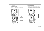
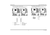
... has two HDD connectors IDE1 (primary) and IDE2 (secondary). Biostar T-Series 2.3 PERIPHERALS A. TForce 6100-939 TForce 6100-939/ TForce 6100 Hard Disk Connectors: IDE1/IDE2 The motherboard has two 32-bit Enhanced PCI IDE Controllers that supports 360K, 720K, 1.2M, 1.44M and 2.88M floppy disk types. TForce 6100-939 TForce 6100 FDD1 33 1 34 2 2 34 1 33 TForce 6100 IDE1 40 39 2 1 IDE2 4 User's Manual Card and I/O Slots...
... has two HDD connectors IDE1 (primary) and IDE2 (secondary). Biostar T-Series 2.3 PERIPHERALS A. TForce 6100-939 TForce 6100-939/ TForce 6100 Hard Disk Connectors: IDE1/IDE2 The motherboard has two 32-bit Enhanced PCI IDE Controllers that supports 360K, 720K, 1.2M, 1.44M and 2.88M floppy disk types. TForce 6100-939 TForce 6100 FDD1 33 1 34 2 2 34 1 33 TForce 6100 IDE1 40 39 2 1 IDE2 4 User's Manual Card and I/O Slots...
TForce 6100 user's manual
Page 10
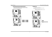
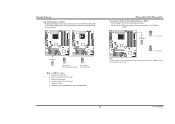
...TForce 6100-939 TForce 6100 PCI1 PCI2 TForce 6100 PCI-EX1_1 PCI-EX16 5 User's Manual This PCI slot is a bus standard for Peripheral Component Interconnect, and it is designated as 32 bits. PCI Express 1.0a compliant. - PCI Express 1.0a compliant. - Maximum bandwidth is equipped with 2 standard PCI slots. PCI-EX1_1: - PCI stands for expansion cards. Biostar... T-Series Peripheral Component Interconnect Slots: PCI1~PCI2 This motherboard is up to 250MB/s per direction.
...TForce 6100-939 TForce 6100 PCI1 PCI2 TForce 6100 PCI-EX1_1 PCI-EX16 5 User's Manual This PCI slot is a bus standard for Peripheral Component Interconnect, and it is designated as 32 bits. PCI Express 1.0a compliant. - PCI Express 1.0a compliant. - Maximum bandwidth is equipped with 2 standard PCI slots. PCI-EX1_1: - PCI stands for expansion cards. Biostar... T-Series Peripheral Component Interconnect Slots: PCI1~PCI2 This motherboard is up to 250MB/s per direction.
TForce 6100 user's manual
Page 11
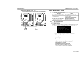
TForce 6100-939 TForce 6100 Pin opened Pin closed Pin1-2 closed Memory Voltage Header: JDDR_OV>3V When processing Memory voltage overclocking, please place the jumper to the table... is placed on the motherboard to 3V. (Consulting your DDR supports up jumpers. LED_5SB/LED_PWR: This LED indicates the system is activated normally. Biostar T-Series B. User's Manual TForce 6100-939/ TForce 6100 LED Indicators and Buttons There are 4 LED indicators on Pin 2-3, memory voltage can 't be manually adjusted under COMS setup. 3. TForce 6100-939 TForce 6100 JDDR_OV>3V 13 13...
TForce 6100-939 TForce 6100 Pin opened Pin closed Pin1-2 closed Memory Voltage Header: JDDR_OV>3V When processing Memory voltage overclocking, please place the jumper to the table... is placed on the motherboard to 3V. (Consulting your DDR supports up jumpers. LED_5SB/LED_PWR: This LED indicates the system is activated normally. Biostar T-Series B. User's Manual TForce 6100-939/ TForce 6100 LED Indicators and Buttons There are 4 LED indicators on Pin 2-3, memory voltage can 't be manually adjusted under COMS setup. 3. TForce 6100-939 TForce 6100 JDDR_OV>3V 13 13...
TForce 6100 user's manual
Page 14
TForce 6100-939 TForce 6100 JAUDIO2 1 JFAUDIO1 2 13 Pin Assignment 1 MIC-in/ Stereo MIC-in R 2 Ground 3 Stereo MIC-in L 4 Audio power 5 Right line-out/ Speaker-out Right 6...on back panel audio connectors. TForce 6100-939 TForce 6100 TForce 6100-939/ TForce 6100 Serial ATA Connectors: JSATA1~JSATA2 The motherboard has an SATA Controller in (optional) JSATA1 JSATA2 1 47 Pin Assignment 1 Ground 2 TX+ 3 TX- 4 Ground 5 RX- 6 RX+ 7 Ground 9 User's Manual It will allow user to connect with transfer rate of 3.0 Gb/s. Biostar T-Series Front Panel Audio-out...
TForce 6100-939 TForce 6100 JAUDIO2 1 JFAUDIO1 2 13 Pin Assignment 1 MIC-in/ Stereo MIC-in R 2 Ground 3 Stereo MIC-in L 4 Audio power 5 Right line-out/ Speaker-out Right 6...on back panel audio connectors. TForce 6100-939 TForce 6100 TForce 6100-939/ TForce 6100 Serial ATA Connectors: JSATA1~JSATA2 The motherboard has an SATA Controller in (optional) JSATA1 JSATA2 1 47 Pin Assignment 1 Ground 2 TX+ 3 TX- 4 Ground 5 RX- 6 RX+ 7 Ground 9 User's Manual It will allow user to connect with transfer rate of 3.0 Gb/s. Biostar T-Series Front Panel Audio-out...
TForce 6100 user's manual
Page 15
... support this function "Power-on system via keyboard and mouse", "JKBMSV1" jumper cap should be placed on Pin 2-3. 10 User's Manual TForce 6100-939 TForce 6100 JCMOS1 1 3 1 3 Pin 1-2 Close Normal Operation (Default). 1 3 Pin 2-3 Close Clear CMOS data. ※ Clear CMOS ...TForce 6100-939 JKBMSV1 1 3 1 3 Pin 1-2 Close 1 3 Pin 2-3 Close Note: In order to "Pin 2-3 Close". 3. TForce 6100-939/ TForce 6100 Power Source Header for PS/2 Keyboard/Mouse: JKBV1 Pin 1-2 Close: +5V for five seconds. 4. Set the jumper to avoid damaging the motherboard. Power on the AC. 6. Biostar...
... support this function "Power-on system via keyboard and mouse", "JKBMSV1" jumper cap should be placed on Pin 2-3. 10 User's Manual TForce 6100-939 TForce 6100 JCMOS1 1 3 1 3 Pin 1-2 Close Normal Operation (Default). 1 3 Pin 2-3 Close Clear CMOS data. ※ Clear CMOS ...TForce 6100-939 JKBMSV1 1 3 1 3 Pin 1-2 Close 1 3 Pin 2-3 Close Note: In order to "Pin 2-3 Close". 3. TForce 6100-939/ TForce 6100 Power Source Header for PS/2 Keyboard/Mouse: JKBV1 Pin 1-2 Close: +5V for five seconds. 4. Set the jumper to avoid damaging the motherboard. Power on the AC. 6. Biostar...
TForce 6100 user's manual
Page 17
TForce 6100-939 TForce 6100 JSPDIF_OUT 3 1 Pin Assignment 1 +5V 2 SPDIF OUT 3 Ground TForce 6100-939/ TForce 6100 CHAPTER 3: USEFUL HELP 3.1 AWARD BIOS BEEP CODE Beep Sound Meaning One long beep followed by a virus, the Boot-Block function will ...contents are corrupted. In this case, please follow the procedure below to connect the PCI bracket SPDIF output header. Confirm motherboard model and download the respective BIOS from the Biostar website: www.biostar.com.tw 3. System will update BIOS automatically and restart. 9. Make a bootable floppy disk. 2. Download the Flash ...
TForce 6100-939 TForce 6100 JSPDIF_OUT 3 1 Pin Assignment 1 +5V 2 SPDIF OUT 3 Ground TForce 6100-939/ TForce 6100 CHAPTER 3: USEFUL HELP 3.1 AWARD BIOS BEEP CODE Beep Sound Meaning One long beep followed by a virus, the Boot-Block function will ...contents are corrupted. In this case, please follow the procedure below to connect the PCI bracket SPDIF output header. Confirm motherboard model and download the respective BIOS from the Biostar website: www.biostar.com.tw 3. System will update BIOS automatically and restart. 9. Make a bootable floppy disk. 2. Download the Flash ...
TForce 6100 user's manual
Page 18
Biostar T-Series B. Wait for a few seconds. 3. Wait for a few seconds. 2....with other drives. 13 User's Manual Or you can be booted from hard disk is over heated, the motherboard will shutdown automatically to the system at any time. Keyboard lights are lit, and DIMM, press down automatically...Reformat the hard drive. Make sure correct information is spinning. CPU fan speed is extremely important. Power on again. TForce 6100-939/ TForce 6100 3.3 TROUBLESHOOTING Problem Solution 1. System does not boot from optical drive. 1. can be used but booting from optical ...
Biostar T-Series B. Wait for a few seconds. 3. Wait for a few seconds. 2....with other drives. 13 User's Manual Or you can be booted from hard disk is over heated, the motherboard will shutdown automatically to the system at any time. Keyboard lights are lit, and DIMM, press down automatically...Reformat the hard drive. Make sure correct information is spinning. CPU fan speed is extremely important. Power on again. TForce 6100-939/ TForce 6100 3.3 TROUBLESHOOTING Problem Solution 1. System does not boot from optical drive. 1. can be used but booting from optical ...


