
TForce 6100 user's manual
Page 1
Biostar T-Series TForce 6100-939/ TForce 6100 FCC Information and Copyright This equipment has been tested and found in a particular installation. PACKAGE CHECKLIST FDD Cable x 1 HDD Cable x 1 SPDIF Cable x 1 User's Manual x 1 Overclock ...
Biostar T-Series TForce 6100-939/ TForce 6100 FCC Information and Copyright This equipment has been tested and found in a particular installation. PACKAGE CHECKLIST FDD Cable x 1 HDD Cable x 1 SPDIF Cable x 1 User's Manual x 1 Overclock ...
TForce 6100 user's manual
Page 2
... and I CHAPTER 1: INTRODUCTION ...1 1.1 MOTHERBOARD FEATURES ...1 1.2 LAYOUT AND COMPONENTS: TFORCE 6100-939...2 1.3 LAYOUT AND COMPONENTS: TFORCE 6100 ...3 CHAPTER 2: HARDWARE INSTALLATIONS ...1 2.1 CPU ASSEMBLY ...1 A. Central Processing Unit (CPU) for Socket 939...1 B. Connectors and Headers:...6 CHAPTER 3: USEFUL HELP...12 3.1 AWARD BIOS BEEP CODE...12 3.2 EXTRA INFORMATION ...12 A. Biostar T-Series TForce 6100-939/ TForce 6100 PACKAGE CHECKLIST ...I /O Slots:...4 B. Central Processing Unit (CPU) for Socket...
... and I CHAPTER 1: INTRODUCTION ...1 1.1 MOTHERBOARD FEATURES ...1 1.2 LAYOUT AND COMPONENTS: TFORCE 6100-939...2 1.3 LAYOUT AND COMPONENTS: TFORCE 6100 ...3 CHAPTER 2: HARDWARE INSTALLATIONS ...1 2.1 CPU ASSEMBLY ...1 A. Central Processing Unit (CPU) for Socket 939...1 B. Connectors and Headers:...6 CHAPTER 3: USEFUL HELP...12 3.1 AWARD BIOS BEEP CODE...12 3.2 EXTRA INFORMATION ...12 A. Biostar T-Series TForce 6100-939/ TForce 6100 PACKAGE CHECKLIST ...I /O Slots:...4 B. Central Processing Unit (CPU) for Socket...
TForce 6100 user's manual
Page 3
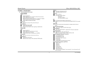
...: Does not support Windows 98SE and Windows ME. Supports AMD Sempron processor. Supports AMD Cool'n'Quiet Technology. Supports HyperTransport Technlology up to 2000MT/s. Biostar T-Series Chapter 1: Introduction 1.1 MOTHERBOARD FEATURES TForce 6100-939 CPU Supports Socket 939. One CD-ROM audio-in connector. 1 User's Manual Supports PIO mode 0~4, Block Mode and Ultra DMA 33...
...: Does not support Windows 98SE and Windows ME. Supports AMD Sempron processor. Supports AMD Cool'n'Quiet Technology. Supports HyperTransport Technlology up to 2000MT/s. Biostar T-Series Chapter 1: Introduction 1.1 MOTHERBOARD FEATURES TForce 6100-939 CPU Supports Socket 939. One CD-ROM audio-in connector. 1 User's Manual Supports PIO mode 0~4, Block Mode and Ultra DMA 33...
TForce 6100 user's manual
Page 4
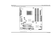
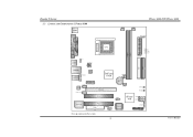
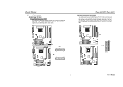
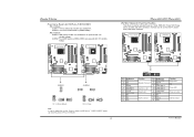
Biostar T-Series 1.2 LAYOUT AND COMPONENTS: TFORCE 6100-939 JKBMS1 JKBV1 J CFAN 1 CPU1 TForce 6100-939/ TForce 6100 J DDR _0V> 3V JCOM1 Socket 939 JPRNT1 DIMMB1 DIMMB2 DIMMA1 DIMMA2 JVGA1 JUSB1 JUS BV1 JATXPWR2 JUSBLAN1 JAUDIO1 JAUDIO2 LAN PHY JNFAN1 J CD IN1 PCI-EX1_1 GeForce 6100 BAT1 Codec JSPDIF_O UT1 PCI-EX16 PCI1 J US BV2 JUS B2 JUSB3 Super I/O PCI2...
Biostar T-Series 1.2 LAYOUT AND COMPONENTS: TFORCE 6100-939 JKBMS1 JKBV1 J CFAN 1 CPU1 TForce 6100-939/ TForce 6100 J DDR _0V> 3V JCOM1 Socket 939 JPRNT1 DIMMB1 DIMMB2 DIMMA1 DIMMA2 JVGA1 JUSB1 JUS BV1 JATXPWR2 JUSBLAN1 JAUDIO1 JAUDIO2 LAN PHY JNFAN1 J CD IN1 PCI-EX1_1 GeForce 6100 BAT1 Codec JSPDIF_O UT1 PCI-EX16 PCI1 J US BV2 JUS B2 JUSB3 Super I/O PCI2...
TForce 6100 user's manual
Page 5
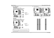
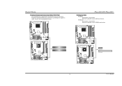
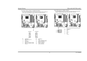
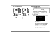
JUS B3 JUS BV2 JUS B2 BIOS nForce 410 JSATA 2 JSATA 1 JCI1 JCMOS 1 J PANEL 1 3 User's Manual Biostar T-Series 1.3 LAYOUT AND COMPONENTS: TFORCE 6100 JKBMS1 TForce 6100-939/ TForce 6100 JCFAN1 J SFAN 2 J DD R_0V> 3V JCOM1 Socket 754 JPRNT1 JVGA1 JUSB1 JUS BV1 JATXPWR2 CPU1 DIMM2 DIMM1 JATXPWR1 L ED _D 1 L ED _D 2 L ED_DI MM L ED_P W R IDE1 IDE2 JUSBLAN1 JAUDIO1 J FAU D IO1 LAN PHY PCI-EX1_1 JCD I N1 Codec JSPDIF_O UT1 GeForce 6100 JNB FAN1 BAT1 PCI-EX16 JSFAN1 RSTSW2 PW R SW 1 PCI1 Super I/O PCI2 FDD1 Note: ■ represents the 1st pin.
JUS B3 JUS BV2 JUS B2 BIOS nForce 410 JSATA 2 JSATA 1 JCI1 JCMOS 1 J PANEL 1 3 User's Manual Biostar T-Series 1.3 LAYOUT AND COMPONENTS: TFORCE 6100 JKBMS1 TForce 6100-939/ TForce 6100 JCFAN1 J SFAN 2 J DD R_0V> 3V JCOM1 Socket 754 JPRNT1 JVGA1 JUSB1 JUS BV1 JATXPWR2 CPU1 DIMM2 DIMM1 JATXPWR1 L ED _D 1 L ED _D 2 L ED_DI MM L ED_P W R IDE1 IDE2 JUSBLAN1 JAUDIO1 J FAU D IO1 LAN PHY PCI-EX1_1 JCD I N1 Codec JSPDIF_O UT1 GeForce 6100 JNB FAN1 BAT1 PCI-EX16 JSFAN1 RSTSW2 PW R SW 1 PCI1 Super I/O PCI2 FDD1 Note: ■ represents the 1st pin.
TForce 6100 user's manual
Page 6
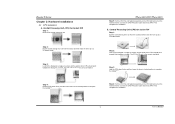
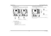
... assembly on the CPU and buckle it on the retention frame. This completes the installation. B. This completes the installation. 1 User's Manual Biostar T-Series Chapter 2: Hardware Installations 2.1 CPU ASSEMBLY A. Step 2: Pull the socket locking lever out from the socket and then raise the lever...Step 2: Look for the triangular cut edge on socket, and the white dot on CPU should point towards this triangular cut edge. TForce 6100-939/ TForce 6100 Step 5: Put the CPU Fan and heatsink assembly on the CPU and buckle it on the retention frame. Central Processing Unit (CPU...
... assembly on the CPU and buckle it on the retention frame. This completes the installation. B. This completes the installation. 1 User's Manual Biostar T-Series Chapter 2: Hardware Installations 2.1 CPU ASSEMBLY A. Step 2: Pull the socket locking lever out from the socket and then raise the lever...Step 2: Look for the triangular cut edge on socket, and the white dot on CPU should point towards this triangular cut edge. TForce 6100-939/ TForce 6100 Step 5: Put the CPU Fan and heatsink assembly on the CPU and buckle it on the retention frame. Central Processing Unit (CPU...
TForce 6100 user's manual
Page 7
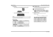
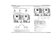
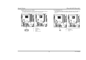
It supports 3 pin head connector. When connecting with Smart Fan Control utilities. Biostar T-Series C. About FAN Headers TForce 6100-939 CPU Fan Power Header: JCFAN1 System Fan Power Headers: JSFAN1/JSFAN2 North Bridge Fan Power Header: JNFAN1 JCFAN1 31 JNFAN1 3 Pin ...Assignment 1 1 Ground 2 +12V 3 FAN RPM rate sense JSFAN1 (Does not support JSFAN2.) 13 JSFAN2 3 1 TForce 6100 CPU Fan Power Header: JCFAN1 System Fan Power Headers: JSFAN1/JSFAN2 North Bridge Fan Power Header: JNBFAN1 JCFAN1 JSFAN2 31 JNBFAN1 1 3 Pin Assignment 1 Ground ...
It supports 3 pin head connector. When connecting with Smart Fan Control utilities. Biostar T-Series C. About FAN Headers TForce 6100-939 CPU Fan Power Header: JCFAN1 System Fan Power Headers: JSFAN1/JSFAN2 North Bridge Fan Power Header: JNFAN1 JCFAN1 31 JNFAN1 3 Pin ...Assignment 1 1 Ground 2 +12V 3 FAN RPM rate sense JSFAN1 (Does not support JSFAN2.) 13 JSFAN2 3 1 TForce 6100 CPU Fan Power Header: JCFAN1 System Fan Power Headers: JSFAN1/JSFAN2 North Bridge Fan Power Header: JNBFAN1 JCFAN1 JSFAN2 31 JNBFAN1 1 3 Pin Assignment 1 Ground ...
TForce 6100 user's manual
Page 8
...remove the DDR modules, push the ejector tabs at both sides of the slot outward at the same time, and pull the modules out vertically. TForce 6100-939/ TForce 6100 C. "DS" represents Double Side DDR memory module. Know your DDR memory module, or the system may not boot up or may not function ... "*" represents leave the DIMM socket empty. Align a DIMM on the slot such that the notch on the DIMM matches the break on the slot. 2. Biostar T-Series A. Insert the DIMM vertically and firmly into the slot until the retaining chip snaps back in place and the DIMM is properly seated. DDR...
...remove the DDR modules, push the ejector tabs at both sides of the slot outward at the same time, and pull the modules out vertically. TForce 6100-939/ TForce 6100 C. "DS" represents Double Side DDR memory module. Know your DDR memory module, or the system may not boot up or may not function ... "*" represents leave the DIMM socket empty. Align a DIMM on the slot such that the notch on the DIMM matches the break on the slot. 2. Biostar T-Series A. Insert the DIMM vertically and firmly into the slot until the retaining chip snaps back in place and the DIMM is properly seated. DDR...
TForce 6100 user's manual
Page 9
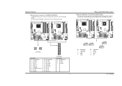
This connector supports the provided floppy drive ribbon cables. Biostar T-Series 2.3 PERIPHERALS A. TForce 6100-939 TForce 6100 FDD1 33 1 34 2 2 34 1 33 TForce 6100 IDE1 40 39 2 1 IDE2 4 User's Manual It has two HDD connectors IDE1 (primary) and IDE2 (secondary... provides a standard floppy disk connector that provide PIO Mode 0~4, Bus Master, and Ultra DMA 33/66/100/133 functionality. TForce 6100-939 TForce 6100-939/ TForce 6100 Hard Disk Connectors: IDE1/IDE2 The motherboard has two 32-bit Enhanced PCI IDE Controllers that supports 360K, 720K, 1.2M,...
This connector supports the provided floppy drive ribbon cables. Biostar T-Series 2.3 PERIPHERALS A. TForce 6100-939 TForce 6100 FDD1 33 1 34 2 2 34 1 33 TForce 6100 IDE1 40 39 2 1 IDE2 4 User's Manual It has two HDD connectors IDE1 (primary) and IDE2 (secondary... provides a standard floppy disk connector that provide PIO Mode 0~4, Bus Master, and Ultra DMA 33/66/100/133 functionality. TForce 6100-939 TForce 6100-939/ TForce 6100 Hard Disk Connectors: IDE1/IDE2 The motherboard has two 32-bit Enhanced PCI IDE Controllers that supports 360K, 720K, 1.2M,...
TForce 6100 user's manual
Page 10
... up to 4GB/s per direction. PCI Express 1.0a compliant. - PCI-EX1_1: - TForce 6100-939 TForce 6100-939/ TForce 6100 PCI-Express Slots PCI-EX16: - Maximum bandwidth is a bus standard for Peripheral Component Interconnect, and it is up to 250MB/s per direction. PCI Express 1.0a compliant. - Biostar T-Series Peripheral Component Interconnect Slots: PCI1~PCI2 This motherboard is designated...
... up to 4GB/s per direction. PCI Express 1.0a compliant. - PCI-EX1_1: - TForce 6100-939 TForce 6100-939/ TForce 6100 PCI-Express Slots PCI-EX16: - Maximum bandwidth is a bus standard for Peripheral Component Interconnect, and it is up to 250MB/s per direction. PCI Express 1.0a compliant. - Biostar T-Series Peripheral Component Interconnect Slots: PCI1~PCI2 This motherboard is designated...
TForce 6100 user's manual
Page 11
...PWRSW1 RSTSW2 RSTSW2 PWRSW1 LED_D1 LED_D2 LED_DIMM LED_PWR LED_D1 and LED_D2: These 2 LED indicate system power on diagnostics. TForce 6100-939 TForce 6100 JDDR_OV>3V 13 13 31 31 13 31 Pin 1-2 Close Pin 2-3 Close (Default) Note: 1. Please ...pin1-2 closed . RSTSW2: This is pin2-3 closed . The default setting is an on . User's Manual TForce 6100-939 TForce 6100 Pin opened Pin closed Pin1-2 closed ", if not, that your DDR supports up jumpers. When the jumper ... on Pin 2-3, memory voltage can 't be manually adjusted under COMS setup. 3. Biostar T-Series B.
...PWRSW1 RSTSW2 RSTSW2 PWRSW1 LED_D1 LED_D2 LED_DIMM LED_PWR LED_D1 and LED_D2: These 2 LED indicate system power on diagnostics. TForce 6100-939 TForce 6100 JDDR_OV>3V 13 13 31 31 13 31 Pin 1-2 Close Pin 2-3 Close (Default) Note: 1. Please ...pin1-2 closed . RSTSW2: This is pin2-3 closed . The default setting is an on . User's Manual TForce 6100-939 TForce 6100 Pin opened Pin closed Pin1-2 closed ", if not, that your DDR supports up jumpers. When the jumper ... on Pin 2-3, memory voltage can 't be manually adjusted under COMS setup. 3. Biostar T-Series B.
TForce 6100 user's manual
Page 12
TForce 6100-939 TForce 6100 TForce 6100-939/ TForce 6100 Headers for USB Ports at Front Panel: JUSB2~JUSB3 This connector allows user to connect 24-pin power connector on the ATX power supply. Biostar T-Series ATX Power Source Connectors: JATXPWR1/JATXPWR2 JATXPWR1 allows user to connect additional USB cables at PC front panel, and also can be connected with...
TForce 6100-939 TForce 6100 TForce 6100-939/ TForce 6100 Headers for USB Ports at Front Panel: JUSB2~JUSB3 This connector allows user to connect 24-pin power connector on the ATX power supply. Biostar T-Series ATX Power Source Connectors: JATXPWR1/JATXPWR2 JATXPWR1 allows user to connect additional USB cables at PC front panel, and also can be connected with...
TForce 6100 user's manual
Page 13
...: JUSBV1: USB ports at JUSB1 and JUSBLAN1. TForce 6100-939 TForce 6100 TForce 6100-939/ TForce 6100 JPANEL1: Header for front USB headers (JUSB2/JUSB3). TForce 6100-939 TForce 6100 JUSBV1 1 3 JUSBV2 31 13 1 31 3 13 Pin 1-2 Close (Default) 1 31 3 Pin 2-3 Close 13 Note: In order to connect the PC case's front panel switch functions. Biostar T-Series Power Source Headers for USB Ports...
...: JUSBV1: USB ports at JUSB1 and JUSBLAN1. TForce 6100-939 TForce 6100 TForce 6100-939/ TForce 6100 JPANEL1: Header for front USB headers (JUSB2/JUSB3). TForce 6100-939 TForce 6100 JUSBV1 1 3 JUSBV2 31 13 1 31 3 13 Pin 1-2 Close (Default) 1 31 3 Pin 2-3 Close 13 Note: In order to connect the PC case's front panel switch functions. Biostar T-Series Power Source Headers for USB Ports...
TForce 6100 user's manual
Page 14
Biostar T-Series Front Panel Audio-out Header: JAUDIO2/JFAUDIO1 This connector will disable the output on the PC case. TForce 6100-939 TForce 6100 TForce 6100-939/ TForce 6100 Serial ATA Connectors: JSATA1~JSATA2 The motherboard has an SATA Controller in (optional) JSATA1 JSATA2 1 47 Pin Assignment 1 Ground 2 TX+ 3 TX- 4 Ground 5 RX- 6 RX+ 7 Ground 9 User's Manual TForce 6100-939 TForce 6100 JAUDIO2 1 JFAUDIO1 2 13...
Biostar T-Series Front Panel Audio-out Header: JAUDIO2/JFAUDIO1 This connector will disable the output on the PC case. TForce 6100-939 TForce 6100 TForce 6100-939/ TForce 6100 Serial ATA Connectors: JSATA1~JSATA2 The motherboard has an SATA Controller in (optional) JSATA1 JSATA2 1 47 Pin Assignment 1 Ground 2 TX+ 3 TX- 4 Ground 5 RX- 6 RX+ 7 Ground 9 User's Manual TForce 6100-939 TForce 6100 JAUDIO2 1 JFAUDIO1 2 13...
TForce 6100 user's manual
Page 15
...Biostar T-Series Clear CMOS Header: JCMOS1 By placing the jumper on the AC. 6. Remove AC power line. 2. Power on pin 2-3, it allows user to restore the BIOS safe setting and the CMOS data, please carefully follow the procedures to "Pin 2-3 Close". 3. Reset your desired password or clear the CMOS data. TForce 6100... placed on Pin 2-3. 10 User's Manual TForce 6100-939 TForce 6100 JCMOS1 1 3 1 3 Pin 1-2 Close Normal Operation (Default). 1 3 Pin 2-3 Close Clear CMOS data. ※ Clear CMOS Procedures: 1. TForce 6100-939/ TForce 6100 Power Source Header for PS/2 Keyboard/Mouse:...
...Biostar T-Series Clear CMOS Header: JCMOS1 By placing the jumper on the AC. 6. Remove AC power line. 2. Power on pin 2-3, it allows user to restore the BIOS safe setting and the CMOS data, please carefully follow the procedures to "Pin 2-3 Close". 3. Reset your desired password or clear the CMOS data. TForce 6100... placed on Pin 2-3. 10 User's Manual TForce 6100-939 TForce 6100 JCMOS1 1 3 1 3 Pin 1-2 Close Normal Operation (Default). 1 3 Pin 2-3 Close Clear CMOS data. ※ Clear CMOS Procedures: 1. TForce 6100-939/ TForce 6100 Power Source Header for PS/2 Keyboard/Mouse:...
TForce 6100 user's manual
Page 16
TForce 6100-939 TForce 6100 TForce 6100-939/ TForce 6100 Case Open Header: JCI1 This connector allows system to monitor PC case open signal 2 Ground 11 User's Manual Biostar T-Series CD-ROM Audio-in Connector: JCDIN1 This connector allows user to the CMOS and show the message on next boot-up. TForce 6100-939 TForce 6100 JCDIN1 1 4 Pin Assignment 1 Left channel input 2 Ground 3 Ground...
TForce 6100-939 TForce 6100 TForce 6100-939/ TForce 6100 Case Open Header: JCI1 This connector allows system to monitor PC case open signal 2 Ground 11 User's Manual Biostar T-Series CD-ROM Audio-in Connector: JCDIN1 This connector allows user to the CMOS and show the message on next boot-up. TForce 6100-939 TForce 6100 JCDIN1 1 4 Pin Assignment 1 Left channel input 2 Ground 3 Ground...
TForce 6100 user's manual
Page 17
... DOS prompt. 7. System will work properly. 12 User's Manual Confirm motherboard model and download the respective BIOS from the Biostar website: www.biostar.com.tw 3. TForce 6100-939 TForce 6100 JSPDIF_OUT 3 1 Pin Assignment 1 +5V 2 SPDIF OUT 3 Ground TForce 6100-939/ TForce 6100 CHAPTER 3: USEFUL HELP 3.1 AWARD BIOS BEEP CODE Beep Sound Meaning One long beep followed by a virus, the Boot...
... DOS prompt. 7. System will work properly. 12 User's Manual Confirm motherboard model and download the respective BIOS from the Biostar website: www.biostar.com.tw 3. TForce 6100-939 TForce 6100 JSPDIF_OUT 3 1 Pin Assignment 1 +5V 2 SPDIF OUT 3 Ground TForce 6100-939/ TForce 6100 CHAPTER 3: USEFUL HELP 3.1 AWARD BIOS BEEP CODE Beep Sound Meaning One long beep followed by a virus, the Boot...
TForce 6100 user's manual
Page 18
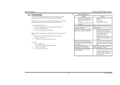
CPU Overheated If the system shuts down automatically after installing second hard drive. 1. Plug in . TForce 6100-939/ TForce 6100 3.3 TROUBLESHOOTING Problem Solution 1. Indicator light on keyboard does not turn on the system again. Backing up data and ...at any time. Clear the CMOS data. (See "JCMOS1: Clear CMOS Header" section) 2. No power to relieve the CPU protection function. 1. Biostar T-Series B. CPU fan speed is in setup. Replace cable. Contact technical support. 2. System inoperative. All hard disks are securely plugged in the...
CPU Overheated If the system shuts down automatically after installing second hard drive. 1. Plug in . TForce 6100-939/ TForce 6100 3.3 TROUBLESHOOTING Problem Solution 1. Indicator light on keyboard does not turn on the system again. Backing up data and ...at any time. Clear the CMOS data. (See "JCMOS1: Clear CMOS Header" section) 2. No power to relieve the CPU protection function. 1. Biostar T-Series B. CPU fan speed is in setup. Replace cable. Contact technical support. 2. System inoperative. All hard disks are securely plugged in the...


