
TForce 6100 user's manual
Page 1
... Part 15 of the FCC Rules. PACKAGE CHECKLIST FDD Cable x 1 HDD Cable x 1 SPDIF Cable x 1 User's Manual x 1 Overclock Guide x 1 Serial ATA Cable x 2 Fully Setup Driver CD x 1 Rear I/O Panel for any implied warranties of merchantability or fitness for ATX Case x 1 USB 2.0 Cable x 1 (optional) i User's Manual Further the vendor reserves the right to revise this user's manual is no representations or warranties with respect to the contents here and specially disclaims any purpose. Duplication of this user's manual. Biostar T-Series TForce 6100-939/ TForce 6100...
... Part 15 of the FCC Rules. PACKAGE CHECKLIST FDD Cable x 1 HDD Cable x 1 SPDIF Cable x 1 User's Manual x 1 Overclock Guide x 1 Serial ATA Cable x 2 Fully Setup Driver CD x 1 Rear I/O Panel for any implied warranties of merchantability or fitness for ATX Case x 1 USB 2.0 Cable x 1 (optional) i User's Manual Further the vendor reserves the right to revise this user's manual is no representations or warranties with respect to the contents here and specially disclaims any purpose. Duplication of this user's manual. Biostar T-Series TForce 6100-939/ TForce 6100...
TForce 6100 user's manual
Page 2
... AND COMPONENTS: TFORCE 6100-939...2 1.3 LAYOUT AND COMPONENTS: TFORCE 6100 ...3 CHAPTER 2: HARDWARE INSTALLATIONS ...1 2.1 CPU ASSEMBLY ...1 A. BIOS Update...12 B. Central Processing Unit (CPU) for Socket 754...1 C. Connectors and Headers:...6 CHAPTER 3: USEFUL HELP...12 3.1 AWARD BIOS BEEP CODE...12 3.2 EXTRA INFORMATION ...12 A. DDR Modules ...3 B. Memory Space...3 C. Know your CPU version ...3 2.3 PERIPHERALS ...4 A. Biostar T-Series TForce 6100-939/ TForce 6100 PACKAGE CHECKLIST ...I /O Slots:...4 B. CPU Overheated...13 3.3 TROUBLESHOOTING ...13 GERMAN...
... AND COMPONENTS: TFORCE 6100-939...2 1.3 LAYOUT AND COMPONENTS: TFORCE 6100 ...3 CHAPTER 2: HARDWARE INSTALLATIONS ...1 2.1 CPU ASSEMBLY ...1 A. BIOS Update...12 B. Central Processing Unit (CPU) for Socket 754...1 C. Connectors and Headers:...6 CHAPTER 3: USEFUL HELP...12 3.1 AWARD BIOS BEEP CODE...12 3.2 EXTRA INFORMATION ...12 A. DDR Modules ...3 B. Memory Space...3 C. Know your CPU version ...3 2.3 PERIPHERALS ...4 A. Biostar T-Series TForce 6100-939/ TForce 6100 PACKAGE CHECKLIST ...I /O Slots:...4 B. CPU Overheated...13 3.3 TROUBLESHOOTING ...13 GERMAN...
TForce 6100 user's manual
Page 3
...CD-ROM audio-in connector. 1 User's Manual Two SATA ports. Maximum memory space is 2GB, supporting 2 DIMM sockets. TForce 6100 CPU Supports Socket 754. Supports HyperTransport Technology up to 1600MT/s. TForce 6100-939/ TForce 6100 Chipset North Bridge: NVIDIA Geforce6100. Environment Control initiatives, H/W Monitor Fan Speed Controller ITE's "Smart Guardian" function IDE 2 on-board connectors support 4 IDE disk drives. AC'97 Audio Sound Codec Chip: ALC655, supports 6 channels audio output. 10/100 LAN PHY PHY: RTL8201BL/RTL8201CL, supports ACPI, PCI...
...CD-ROM audio-in connector. 1 User's Manual Two SATA ports. Maximum memory space is 2GB, supporting 2 DIMM sockets. TForce 6100 CPU Supports Socket 754. Supports HyperTransport Technology up to 1600MT/s. TForce 6100-939/ TForce 6100 Chipset North Bridge: NVIDIA Geforce6100. Environment Control initiatives, H/W Monitor Fan Speed Controller ITE's "Smart Guardian" function IDE 2 on-board connectors support 4 IDE disk drives. AC'97 Audio Sound Codec Chip: ALC655, supports 6 channels audio output. 10/100 LAN PHY PHY: RTL8201BL/RTL8201CL, supports ACPI, PCI...
TForce 6100 user's manual
Page 4
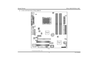
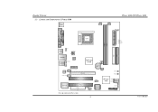
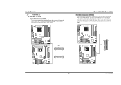
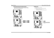
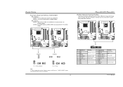
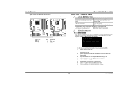
... JATXPWR2 JUSBLAN1 JAUDIO1 JAUDIO2 LAN PHY JNFAN1 J CD IN1 PCI-EX1_1 GeForce 6100 BAT1 Codec JSPDIF_O UT1 PCI-EX16 PCI1 J US BV2 JUS B2 JUSB3 Super I/O PCI2 FDD1 J SFAN 2 BIOS L ED_5 SB L ED_DI MM L ED_D2 L ED_D1 Note: ■ represents the 1st pin. 2 JATXPWR1 IDE2 IDE1 J SFAN 1 PWRSW1 R ST SW 2 nForce 410 J SATA 2 J SATA 1 J CI 1 J CM OS 1 J PAN EL 1 User's Manual
... JATXPWR2 JUSBLAN1 JAUDIO1 JAUDIO2 LAN PHY JNFAN1 J CD IN1 PCI-EX1_1 GeForce 6100 BAT1 Codec JSPDIF_O UT1 PCI-EX16 PCI1 J US BV2 JUS B2 JUSB3 Super I/O PCI2 FDD1 J SFAN 2 BIOS L ED_5 SB L ED_DI MM L ED_D2 L ED_D1 Note: ■ represents the 1st pin. 2 JATXPWR1 IDE2 IDE1 J SFAN 1 PWRSW1 R ST SW 2 nForce 410 J SATA 2 J SATA 1 J CI 1 J CM OS 1 J PAN EL 1 User's Manual
TForce 6100 user's manual
Page 5
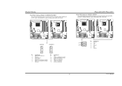
JUS B3 JUS BV2 JUS B2 BIOS nForce 410 JSATA 2 JSATA 1 JCI1 JCMOS 1 J PANEL 1 3 User's Manual Biostar T-Series 1.3 LAYOUT AND COMPONENTS: TFORCE 6100 JKBMS1 TForce 6100-939/ TForce 6100 JCFAN1 J SFAN 2 J DD R_0V> 3V JCOM1 Socket 754 JPRNT1 JVGA1 JUSB1 JUS BV1 JATXPWR2 CPU1 DIMM2 DIMM1 JATXPWR1 L ED _D 1 L ED _D 2 L ED_DI MM L ED_P W R IDE1 IDE2 JUSBLAN1 JAUDIO1 J FAU D IO1 LAN PHY PCI-EX1_1 JCD I N1 Codec JSPDIF_O UT1 GeForce 6100 JNB FAN1 BAT1 PCI-EX16 JSFAN1 RSTSW2 PW R SW 1 PCI1 Super I/O PCI2 FDD1 Note: ■ represents the 1st pin.
JUS B3 JUS BV2 JUS B2 BIOS nForce 410 JSATA 2 JSATA 1 JCI1 JCMOS 1 J PANEL 1 3 User's Manual Biostar T-Series 1.3 LAYOUT AND COMPONENTS: TFORCE 6100 JKBMS1 TForce 6100-939/ TForce 6100 JCFAN1 J SFAN 2 J DD R_0V> 3V JCOM1 Socket 754 JPRNT1 JVGA1 JUSB1 JUS BV1 JATXPWR2 CPU1 DIMM2 DIMM1 JATXPWR1 L ED _D 1 L ED _D 2 L ED_DI MM L ED_P W R IDE1 IDE2 JUSBLAN1 JAUDIO1 J FAU D IO1 LAN PHY PCI-EX1_1 JCD I N1 Codec JSPDIF_O UT1 GeForce 6100 JNB FAN1 BAT1 PCI-EX16 JSFAN1 RSTSW2 PW R SW 1 PCI1 Super I/O PCI2 FDD1 Note: ■ represents the 1st pin.
TForce 6100 user's manual
Page 6
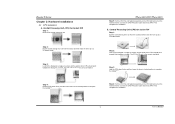
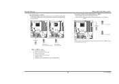
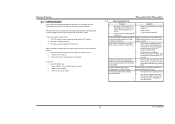
Biostar T-Series Chapter 2: Hardware Installations 2.1 CPU ASSEMBLY A. B. Step 3: Hold the CPU down firmly, and then lower the lever to locked position to a 90-degree angle. Connect the CPU FAN power cable into the JCFAN1. TForce 6100-939/ TForce 6100 Step 5: Put the CPU Fan and heatsink assembly on the CPU and buckle it on the retention frame. Step 4: Put the CPU Fan and heatsink assembly on the CPU and buckle it on the...
Biostar T-Series Chapter 2: Hardware Installations 2.1 CPU ASSEMBLY A. B. Step 3: Hold the CPU down firmly, and then lower the lever to locked position to a 90-degree angle. Connect the CPU FAN power cable into the JCFAN1. TForce 6100-939/ TForce 6100 Step 5: Put the CPU Fan and heatsink assembly on the CPU and buckle it on the retention frame. Step 4: Put the CPU Fan and heatsink assembly on the CPU and buckle it on the...
TForce 6100 user's manual
Page 7
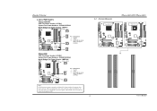
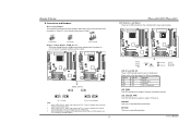
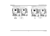
... 2 +12V 3 FAN RPM rate sense (Does not support JSFAN2.) JSFAN1 1 3 Note: JCFAN1 reserves system cooling fan with wires onto connectors, please note that the red wire is the positive and should be connected to pin#2, and the black wire is Ground and should be connected to GND. 2.2 SYSTEM MEMORY TForce 6100-939 2 DIMMB2 DIMMB1 DIMMA2 DIMMA1 DIMMB2 DIMMB1 TForce 6100-939/ TForce 6100 TForce 6100 User's Manual When connecting with Smart Fan Control utilities. It supports 3 pin head connector. Biostar T-Series C.
... 2 +12V 3 FAN RPM rate sense (Does not support JSFAN2.) JSFAN1 1 3 Note: JCFAN1 reserves system cooling fan with wires onto connectors, please note that the red wire is the positive and should be connected to pin#2, and the black wire is Ground and should be connected to GND. 2.2 SYSTEM MEMORY TForce 6100-939 2 DIMMB2 DIMMB1 DIMMA2 DIMMA1 DIMMB2 DIMMB1 TForce 6100-939/ TForce 6100 TForce 6100 User's Manual When connecting with Smart Fan Control utilities. It supports 3 pin head connector. Biostar T-Series C.
TForce 6100 user's manual
Page 8
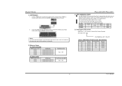
... slot. 2. B. Total Memory Size (MB) Max is 4 GB. "DS" represents Double Side DDR memory module. Biostar T-Series A. Insert the DIMM vertically and firmly into the slot until the retaining chip snaps back in place and the DIMM is properly seated. Know your DDR memory module, or the system may not boot up or may not function properly. (Please refer to install your CPU version AMD...
... slot. 2. B. Total Memory Size (MB) Max is 4 GB. "DS" represents Double Side DDR memory module. Biostar T-Series A. Insert the DIMM vertically and firmly into the slot until the retaining chip snaps back in place and the DIMM is properly seated. Know your DDR memory module, or the system may not boot up or may not function properly. (Please refer to install your CPU version AMD...
TForce 6100 user's manual
Page 9
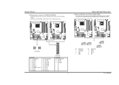
Biostar T-Series 2.3 PERIPHERALS A. TForce 6100-939 TForce 6100-939/ TForce 6100 Hard Disk Connectors: IDE1/IDE2 The motherboard has two 32-bit Enhanced PCI IDE Controllers that supports 360K, 720K, 1.2M, 1.44M and 2.88M floppy disk types. The IDE connectors can connect a master and a slave drive, so you can connect up to IDE1. This connector supports the provided floppy drive ribbon cables. It has two HDD connectors IDE1 (primary) and IDE2 (secondary). The first hard drive should always be connected to four hard disk drives. TForce 6100-939 TForce 6100 FDD1 33 1 34...
Biostar T-Series 2.3 PERIPHERALS A. TForce 6100-939 TForce 6100-939/ TForce 6100 Hard Disk Connectors: IDE1/IDE2 The motherboard has two 32-bit Enhanced PCI IDE Controllers that supports 360K, 720K, 1.2M, 1.44M and 2.88M floppy disk types. The IDE connectors can connect a master and a slave drive, so you can connect up to IDE1. This connector supports the provided floppy drive ribbon cables. It has two HDD connectors IDE1 (primary) and IDE2 (secondary). The first hard drive should always be connected to four hard disk drives. TForce 6100-939 TForce 6100 FDD1 33 1 34...
TForce 6100 user's manual
Page 10
... is up to 250MB/s per direction. TForce 6100-939 TForce 6100 PCI1 PCI2 TForce 6100 PCI-EX1_1 PCI-EX16 5 User's Manual PCI Express 1.0a compliant. - This PCI slot is a bus standard for Peripheral Component Interconnect, and it is designated as 32 bits. Maximum bandwidth is equipped with 2 standard PCI slots. PCI stands for expansion cards. TForce 6100-939 TForce 6100-939/ TForce 6100 PCI-Express Slots PCI-EX16: - Biostar T-Series Peripheral Component Interconnect Slots: PCI1~PCI2 This motherboard is up to 4GB/s per direction.
... is up to 250MB/s per direction. TForce 6100-939 TForce 6100 PCI1 PCI2 TForce 6100 PCI-EX1_1 PCI-EX16 5 User's Manual PCI Express 1.0a compliant. - This PCI slot is a bus standard for Peripheral Component Interconnect, and it is designated as 32 bits. Maximum bandwidth is equipped with 2 standard PCI slots. PCI stands for expansion cards. TForce 6100-939 TForce 6100-939/ TForce 6100 PCI-Express Slots PCI-EX16: - Biostar T-Series Peripheral Component Interconnect Slots: PCI1~PCI2 This motherboard is up to 4GB/s per direction.
TForce 6100 user's manual
Page 11
... ON Normal ON OFF Memory Error OFF ON VGA Error OFF OFF CPU / Chipset Error LED_DIMM: This LED indicates the voltage of memory is placed on Pin 1-2, memory voltage will be fixed at 3.3V automatically, and can be adjusted under CMOS setup. 2. The default setting is placed on . User's Manual TForce 6100-939 TForce 6100 JDDR_OV>3V 13 13 31 31 13 31 Pin 1-2 Close Pin 2-3 Close (Default) Note: 1. Connectors and Headers: How to setup Jumpers The illustration shows how...
... ON Normal ON OFF Memory Error OFF ON VGA Error OFF OFF CPU / Chipset Error LED_DIMM: This LED indicates the voltage of memory is placed on Pin 1-2, memory voltage will be fixed at 3.3V automatically, and can be adjusted under CMOS setup. 2. The default setting is placed on . User's Manual TForce 6100-939 TForce 6100 JDDR_OV>3V 13 13 31 31 13 31 Pin 1-2 Close Pin 2-3 Close (Default) Note: 1. Connectors and Headers: How to setup Jumpers The illustration shows how...
TForce 6100 user's manual
Page 12
... Ground 1 12 JATXPWR1 JATXPWR2: Pin Assignment 1 +12V 2 +12V 3 Ground 4 Ground 7 JUSB2 2 1 Pin Assignment 1 +5V (fused) 2 +5V (fused) 3 USB- 4 USB- 5 USB+ JUSB3 10 9 Pin Assignment 6 USB+ 7 Ground 8 Ground 9 Key 10 NC JUSB3 2 1 JUSB2 10 9 User's Manual Biostar T-Series ATX Power Source Connectors: JATXPWR1/JATXPWR2 JATXPWR1 allows user to connect additional USB cables at Front Panel: JUSB2~JUSB3 This connector allows user to connect 24-pin power connector on the ATX power supply. By connecting JATXPWR2, it will provide +12V to CPU power circuit.
... Ground 1 12 JATXPWR1 JATXPWR2: Pin Assignment 1 +12V 2 +12V 3 Ground 4 Ground 7 JUSB2 2 1 Pin Assignment 1 +5V (fused) 2 +5V (fused) 3 USB- 4 USB- 5 USB+ JUSB3 10 9 Pin Assignment 6 USB+ 7 Ground 8 Ground 9 Key 10 NC JUSB3 2 1 JUSB2 10 9 User's Manual Biostar T-Series ATX Power Source Connectors: JATXPWR1/JATXPWR2 JATXPWR1 allows user to connect additional USB cables at Front Panel: JUSB2~JUSB3 This connector allows user to connect 24-pin power connector on the ATX power supply. By connecting JATXPWR2, it will provide +12V to CPU power circuit.
TForce 6100 user's manual
Page 13
... panel switch functions. TForce 6100-939 TForce 6100 TForce 6100-939/ TForce 6100 JPANEL1: Header for front USB headers (JUSB2/JUSB3). JUSBV2: Front USB headers (JUSB2/JUSB3) are powered with +5V standby voltage. It allows user to support this function "Power-on system via USB device," "JUSBV1/JUSBV2" jumper cap should be placed on Pin 2-3 individually. 8 Pin Assignment 1 +5V 3 N/A 5 N/A 7 Speaker 9 HDD LED (+) 11 HDD LED (-) 13 Ground 15 Reset control 17 N/A 19 N/A 21 +5V 23 IRTX JPANEL1 2 24 1 23 Function Speaker Connector Hard drive LED Reset button IrDA Connector Pin...
... panel switch functions. TForce 6100-939 TForce 6100 TForce 6100-939/ TForce 6100 JPANEL1: Header for front USB headers (JUSB2/JUSB3). JUSBV2: Front USB headers (JUSB2/JUSB3) are powered with +5V standby voltage. It allows user to support this function "Power-on system via USB device," "JUSBV1/JUSBV2" jumper cap should be placed on Pin 2-3 individually. 8 Pin Assignment 1 +5V 3 N/A 5 N/A 7 Speaker 9 HDD LED (+) 11 HDD LED (-) 13 Ground 15 Reset control 17 N/A 19 N/A 21 +5V 23 IRTX JPANEL1 2 24 1 23 Function Speaker Connector Hard drive LED Reset button IrDA Connector Pin...
TForce 6100 user's manual
Page 14
... with 2 channels SATA interface, it satisfies SATA 2.0 spec with the front audio output headers on back panel audio connectors. It will allow user to connect with transfer rate of 3.0 Gb/s. TForce 6100-939 TForce 6100 TForce 6100-939/ TForce 6100 Serial ATA Connectors: JSATA1~JSATA2 The motherboard has an SATA Controller in (optional) JSATA1 JSATA2 1 47 Pin Assignment 1 Ground 2 TX+ 3 TX- 4 Ground 5 RX- 6 RX+ 7 Ground 9 User's Manual Biostar T-Series Front Panel Audio-out Header: JAUDIO2/JFAUDIO1 This connector will disable the output on the PC case.
... with 2 channels SATA interface, it satisfies SATA 2.0 spec with the front audio output headers on back panel audio connectors. It will allow user to connect with transfer rate of 3.0 Gb/s. TForce 6100-939 TForce 6100 TForce 6100-939/ TForce 6100 Serial ATA Connectors: JSATA1~JSATA2 The motherboard has an SATA Controller in (optional) JSATA1 JSATA2 1 47 Pin Assignment 1 Ground 2 TX+ 3 TX- 4 Ground 5 RX- 6 RX+ 7 Ground 9 User's Manual Biostar T-Series Front Panel Audio-out Header: JAUDIO2/JFAUDIO1 This connector will disable the output on the PC case.
TForce 6100 user's manual
Page 15
... BIOS safe setting and the CMOS data, please carefully follow the procedures to avoid damaging the motherboard. Biostar T-Series Clear CMOS Header: JCMOS1 By placing the jumper on Pin 2-3. 10 User's Manual Set the jumper to "Pin 1-2 Close". 5. Reset your desired password or clear the CMOS data. TForce 6100-939/ TForce 6100 Power Source Header for PS/2 Keyboard/Mouse: JKBV1 Pin 1-2 Close: +5V for five seconds. 4. Power on the AC. 6. Pin 2-3 Close: PS/2 keyboard and mouse are powered with +5V standby voltage. Set the jumper to "Pin...
... BIOS safe setting and the CMOS data, please carefully follow the procedures to avoid damaging the motherboard. Biostar T-Series Clear CMOS Header: JCMOS1 By placing the jumper on Pin 2-3. 10 User's Manual Set the jumper to "Pin 1-2 Close". 5. Reset your desired password or clear the CMOS data. TForce 6100-939/ TForce 6100 Power Source Header for PS/2 Keyboard/Mouse: JKBV1 Pin 1-2 Close: +5V for five seconds. 4. Power on the AC. 6. Pin 2-3 Close: PS/2 keyboard and mouse are powered with +5V standby voltage. Set the jumper to "Pin...
TForce 6100 user's manual
Page 16
... monitor PC case open signal 2 Ground 11 User's Manual TForce 6100-939 TForce 6100 TForce 6100-939/ TForce 6100 Case Open Header: JCI1 This connector allows system to the CMOS and show the message on next boot-up. TForce 6100-939 TForce 6100 JCDIN1 1 4 Pin Assignment 1 Left channel input 2 Ground 3 Ground 4 Right channel input JCI1 12 Pin Assignment 1 Case open status. Biostar T-Series CD-ROM Audio-in Connector: JCDIN1 This connector allows user to connect the audio source from a variety of devices, like CD-ROM, DVD-ROM, PCI sound card, PCI TV tuner card...
... monitor PC case open signal 2 Ground 11 User's Manual TForce 6100-939 TForce 6100 TForce 6100-939/ TForce 6100 Case Open Header: JCI1 This connector allows system to the CMOS and show the message on next boot-up. TForce 6100-939 TForce 6100 JCDIN1 1 4 Pin Assignment 1 Left channel input 2 Ground 3 Ground 4 Right channel input JCI1 12 Pin Assignment 1 Case open status. Biostar T-Series CD-ROM Audio-in Connector: JCDIN1 This connector allows user to connect the audio source from a variety of devices, like CD-ROM, DVD-ROM, PCI sound card, PCI TV tuner card...
TForce 6100 user's manual
Page 17
TForce 6100-939 TForce 6100 JSPDIF_OUT 3 1 Pin Assignment 1 +5V 2 SPDIF OUT 3 Ground TForce 6100-939/ TForce 6100 CHAPTER 3: USEFUL HELP 3.1 AWARD BIOS BEEP CODE Beep Sound Meaning One long beep followed by a virus, the Boot-Block function will shut down automatically One Short beep when system boots-up to DOS prompt. 7. Copy "AWDFLASH.exe" and respective BIOS onto floppy disk. 5. System will boot-up No error found or video card memory bad High-low siren sound CPU overheated System will help to update BIOS or BIOS is shown...
TForce 6100-939 TForce 6100 JSPDIF_OUT 3 1 Pin Assignment 1 +5V 2 SPDIF OUT 3 Ground TForce 6100-939/ TForce 6100 CHAPTER 3: USEFUL HELP 3.1 AWARD BIOS BEEP CODE Beep Sound Meaning One long beep followed by a virus, the Boot-Block function will shut down automatically One Short beep when system boots-up to DOS prompt. 7. Copy "AWDFLASH.exe" and respective BIOS onto floppy disk. 5. System will boot-up No error found or video card memory bad High-low siren sound CPU overheated System will help to update BIOS or BIOS is shown...
TForce 6100 user's manual
Page 18
... disk controller board. Replace cable. System only boots from hard disk 1. Cannot boot system after power on . 3. In this case, please double check: 1. Plug in the power cord and boot up data and application files. Make sure power cable is spinning. Make sure both ends of the on, power indicator lights are lit, and DIMM, press down automatically after installing second hard drive. 1. snaps into place. When the CPU is rotating normally. 3. TForce 6100-939/ TForce 6100 3.3 TROUBLESHOOTING Problem...
... disk controller board. Replace cable. System only boots from hard disk 1. Cannot boot system after power on . 3. In this case, please double check: 1. Plug in the power cord and boot up data and application files. Make sure power cable is spinning. Make sure both ends of the on, power indicator lights are lit, and DIMM, press down automatically after installing second hard drive. 1. snaps into place. When the CPU is rotating normally. 3. TForce 6100-939/ TForce 6100 3.3 TROUBLESHOOTING Problem...


