Bios Setup
Page 4
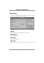
...Hard Drive C onfiguration [00: 00:00] [Tue 01/01/2008] S elect Screen S elect Item +- System Time Set the system internal clock. System Memory Shows system memory size. Use [+] or [-] to select a field. Main Advan ced BIOS SETU P U TILITY PCIPnP Boot Chipset T-Series Exit System Overvie w AMI BIOS ...Version :01. 01.01 Build Date:01/ 01/08 System Memory Size : Use [ENTER], [TAB] or [SHIFT-TAB] to configure system Time. AMI BIOS Shows system information, including BIOS version and built date. TA790GX A3+ BIOS Manual 1 Main Menu Once you set the date. 3
...Hard Drive C onfiguration [00: 00:00] [Tue 01/01/2008] S elect Screen S elect Item +- System Time Set the system internal clock. System Memory Shows system memory size. Use [+] or [-] to select a field. Main Advan ced BIOS SETU P U TILITY PCIPnP Boot Chipset T-Series Exit System Overvie w AMI BIOS ...Version :01. 01.01 Build Date:01/ 01/08 System Memory Size : Use [ENTER], [TAB] or [SHIFT-TAB] to configure system Time. AMI BIOS Shows system information, including BIOS version and built date. TA790GX A3+ BIOS Manual 1 Main Menu Once you set the date. 3

Bios Setup
Page 9
...Calibration (ACC) is made available to the operating system at boot time and uses the information to better allocate memory and schedule software threads for maximum perform ance. When enabled, it will improve the stability of your system ... +12% / -4% / -6% / -8% / -10% / -12% C1E Support T his item controls whether the SRAT is an enhanced technology fo r overclocking, needing support from both chipset and CPU. TA790GX A3+ BIOS Manual Secure Virtual Machine Mode Virtualization T echnology can virtually separate your system when the system is set to "All Cores" or "Per Core". Options...
...Calibration (ACC) is made available to the operating system at boot time and uses the information to better allocate memory and schedule software threads for maximum perform ance. When enabled, it will improve the stability of your system ... +12% / -4% / -6% / -8% / -10% / -12% C1E Support T his item controls whether the SRAT is an enhanced technology fo r overclocking, needing support from both chipset and CPU. TA790GX A3+ BIOS Manual Secure Virtual Machine Mode Virtualization T echnology can virtually separate your system when the system is set to "All Cores" or "Per Core". Options...
Bios Setup
Page 18
... allows such snooping to be used by Legacy ISA devices. DMA Channel 0 DMA Channel 1 DMA Channel 3 DMA Channel 5 DMA Channel 6 DMA Channel 7 Reserved Memory Size [Available] [Available] [Available] [Available] [Available] [Available] [Disabled] Select Screen Select Item +- Options: Yes (Default) / No Palette Snooping Some... Allocate IRQ to PCI V GA T his item controls how long a PCI device can retain control of the bus before another PCI device. TA790GX A3+ BIOS Manual PCI Latency Timer T his item allows BIOS to choose a IRQ to assign for the PCI VGA card. Reserved: Specified IRQ ...
... allows such snooping to be used by Legacy ISA devices. DMA Channel 0 DMA Channel 1 DMA Channel 3 DMA Channel 5 DMA Channel 6 DMA Channel 7 Reserved Memory Size [Available] [Available] [Available] [Available] [Available] [Available] [Disabled] Select Screen Select Item +- Options: Yes (Default) / No Palette Snooping Some... Allocate IRQ to PCI V GA T his item controls how long a PCI device can retain control of the bus before another PCI device. TA790GX A3+ BIOS Manual PCI Latency Timer T his item allows BIOS to choose a IRQ to assign for the PCI VGA card. Reserved: Specified IRQ ...
Bios Setup
Page 19
...Reserved DMA Channel 0/1/3/5/6/7 T hese items will allow you to assign each DMA channel a type, depending on the type of device using the interrupt. TA790GX A3+ BIOS Manual IRQ3/4/5/7/9/10/11/14/15 T hese items will allow you to assign each system interrupt a type, depending on the type of device ...using the channel. Options: Available (Default) / Reserved Reserved Memory Size T his item allows BIOS to assign automatically. T he option " Available" means the channel is going to reserve cert ain...
...Reserved DMA Channel 0/1/3/5/6/7 T hese items will allow you to assign each DMA channel a type, depending on the type of device using the interrupt. TA790GX A3+ BIOS Manual IRQ3/4/5/7/9/10/11/14/15 T hese items will allow you to assign each system interrupt a type, depending on the type of device ...using the channel. Options: Available (Default) / Reserved Reserved Memory Size T his item allows BIOS to assign automatically. T he option " Available" means the channel is going to reserve cert ain...
Bios Setup
Page 20
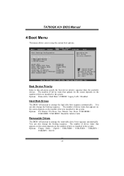
...Full Screen LOGO S how [ Enabled] AddOn ROM Display Mode [ Force BIOS] Bootu p Num-Lock [ ON] Inter rupt 19 Captu re [ Enabled] Ignor e Memory Erro r Messages [ Disabled] BOOT SUCCESS BEEP [ Enabled] Spec ifies the Boot Device Prio rity sequenc e. S elect Screen S elect Item En terG o to arrange ...een F1 G eneral Help F1 0 S ave and Exit ES C E xit vxx.xx (C)C opyright 198 5-200x, Amer ican Megatre nds, Inc. TA790GX A3+ BIOS Manual 4 Boot Menu T his menu allows you to arrange the removable drive boot sequence automatically. You can also change the booting sequence. Master /...
...Full Screen LOGO S how [ Enabled] AddOn ROM Display Mode [ Force BIOS] Bootu p Num-Lock [ ON] Inter rupt 19 Captu re [ Enabled] Ignor e Memory Erro r Messages [ Disabled] BOOT SUCCESS BEEP [ Enabled] Spec ifies the Boot Device Prio rity sequenc e. S elect Screen S elect Item En terG o to arrange ...een F1 G eneral Help F1 0 S ave and Exit ES C E xit vxx.xx (C)C opyright 198 5-200x, Amer ican Megatre nds, Inc. TA790GX A3+ BIOS Manual 4 Boot Menu T his menu allows you to arrange the removable drive boot sequence automatically. You can also change the booting sequence. Master /...

Bios Setup
Page 21
...Default) / Disabled Full Screen LOGO Show T his item sets the display mode for option ROM. Options: Enabled (Default) / Disabled Ignore Memory Error Messages When set to Enabled, BIOS will let user know boot success with beep. Options: Enabled (Default) / Disabled 20 Options: ...memory error messages. Slave / Sec. Options: ON (Default) / OFF Interrupt 19 Capture When set to Enabled, this option will attempt to arrange the CD/DVD drive boot sequence automatically. Slave / USB CDROM0 / USB CDROM 1 Quick Boot Enabling this item allows the option ROMs to trap interrupt 19. TA790GX A3...
...Default) / Disabled Full Screen LOGO Show T his item sets the display mode for option ROM. Options: Enabled (Default) / Disabled Ignore Memory Error Messages When set to Enabled, BIOS will let user know boot success with beep. Options: Enabled (Default) / Disabled 20 Options: ...memory error messages. Slave / Sec. Options: ON (Default) / OFF Interrupt 19 Capture When set to Enabled, this option will attempt to arrange the CD/DVD drive boot sequence automatically. Slave / USB CDROM0 / USB CDROM 1 Quick Boot Enabling this item allows the option ROMs to trap interrupt 19. TA790GX A3...
Bios Setup
Page 22
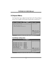
... Exit ES C E xit vxx.xx (C)C opyright 198 5-200x, Amer ican Megatre nds, Inc. T his submenu allows you to system memory resources, such as DRAM. It also coordinates communications with the PCI bus. TA790GX A3+ BIOS Manual 5 Chipset Menu T his chipset manage bus speeds and access to configure the speci fic features of the...
... Exit ES C E xit vxx.xx (C)C opyright 198 5-200x, Amer ican Megatre nds, Inc. T his submenu allows you to system memory resources, such as DRAM. It also coordinates communications with the PCI bus. TA790GX A3+ BIOS Manual 5 Chipset Menu T his chipset manage bus speeds and access to configure the speci fic features of the...
Bios Setup
Page 25
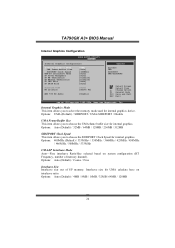
... / 32MB / 64MB / 128MB 24 Options: UMA (Default) / SIDEPORT / UMA+SIDEPORT / Disable UMA FrameBuffer Size T his item allows you to select the memory mode used for internal graphics. Options: 400MHz (Default) / 333MHz+ / 350MHz / 366MHz / 425MHz / 450MHz / 466MHz / 500MHz / 533MHz UMA-SP Interleave...allows you to choose the SIDEPORT Clock Speed for UMA calculate bas e on system configuration (HT Frequency, number o f memory channel). TA790GX A3+ BIOS Manual Internal Graphics Configuration BIOS S ETUP UTILITY Chips et Inter nal Graphics Configuratio n Inter nal Graphics Mode UMA ...
... / 32MB / 64MB / 128MB 24 Options: UMA (Default) / SIDEPORT / UMA+SIDEPORT / Disable UMA FrameBuffer Size T his item allows you to select the memory mode used for internal graphics. Options: 400MHz (Default) / 333MHz+ / 350MHz / 366MHz / 425MHz / 450MHz / 466MHz / 500MHz / 533MHz UMA-SP Interleave...allows you to choose the SIDEPORT Clock Speed for UMA calculate bas e on system configuration (HT Frequency, number o f memory channel). TA790GX A3+ BIOS Manual Internal Graphics Configuration BIOS S ETUP UTILITY Chips et Inter nal Graphics Configuratio n Inter nal Graphics Mode UMA ...
Bios Setup
Page 26
... location. Options: Enabled (Default) / Disabled 25 TA790GX A3+ BIOS Manual Interleave Ratio (SP:UMA) Options: Auto (Default) / 1:1 / 1:3 / 1:7 / 1:15 / 3:5 / 3:13 / 5:11 / 7:9 SP Power Managment T his item allows you to control SP NB/Memory Termination. Options: Auto (Default) / Dynamic CKE... / Dynamic CMD / Dynamic / CLK / Disabled SP NB/Memory Termination T his item allows you to select SP Power Managment fun ction. Options: Auto (Default) / Disabled ...
... location. Options: Enabled (Default) / Disabled 25 TA790GX A3+ BIOS Manual Interleave Ratio (SP:UMA) Options: Auto (Default) / 1:1 / 1:3 / 1:7 / 1:15 / 3:5 / 3:13 / 5:11 / 7:9 SP Power Managment T his item allows you to control SP NB/Memory Termination. Options: Auto (Default) / Dynamic CKE... / Dynamic CMD / Dynamic / CLK / Disabled SP NB/Memory Termination T his item allows you to select SP Power Managment fun ction. Options: Auto (Default) / Disabled ...
Bios Setup
Page 36
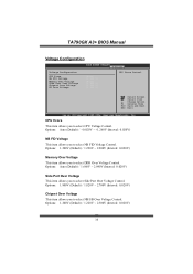
Options: 1.200V (Default) / 1.220V ~ 2.200V (Interval: 0.020V) Memory Over Voltage T his item allows you to select NB/SB Over Voltage Control. Options: 1.800V (Default) / 1.820V ~ 2.700V (Interval: 0.020V) Chipset Over Voltage T his item ... FID Voltage Control. Options: Auto (Default) / 1.660V ~ 2.840V (Interval: 0.020V) Side Port Over Voltage T his item allows you to select Side Port Over Voltage Control. TA790GX A3+ BIOS Manual Voltage Configuration Volta ge Configurat ion CPU V core NB FI D Voltage Memor y Over Volt age Side Port Over Vol tage Chips et Over...
Options: 1.200V (Default) / 1.220V ~ 2.200V (Interval: 0.020V) Memory Over Voltage T his item allows you to select NB/SB Over Voltage Control. Options: 1.800V (Default) / 1.820V ~ 2.700V (Interval: 0.020V) Chipset Over Voltage T his item ... FID Voltage Control. Options: Auto (Default) / 1.660V ~ 2.840V (Interval: 0.020V) Side Port Over Voltage T his item allows you to select Side Port Over Voltage Control. TA790GX A3+ BIOS Manual Voltage Configuration Volta ge Configurat ion CPU V core NB FI D Voltage Memor y Over Volt age Side Port Over Vol tage Chips et Over...

Bios Setup
Page 37
...DDR3-1066 / DDR3-1333 / DDR3-1600 / Auto DRAM Timing Mode T his item allows you to choose to control the Memory Clock. Memory Clock Mode T his item allows you to manually or automatically regul ate the DRAM T iming. TA790GX A3+ BIOS Manual HT Ov er Voltage T his item allows you to set the... Memory Clock. S elect Screen S elect Item +- Options: Auto (Default) / Manual / Limit Memclock Value T his item allows you to select ...
...DDR3-1066 / DDR3-1333 / DDR3-1600 / Auto DRAM Timing Mode T his item allows you to choose to control the Memory Clock. Memory Clock Mode T his item allows you to manually or automatically regul ate the DRAM T iming. TA790GX A3+ BIOS Manual HT Ov er Voltage T his item allows you to set the... Memory Clock. S elect Screen S elect Item +- Options: Auto (Default) / Manual / Limit Memclock Value T his item allows you to select ...
Bios Setup
Page 40
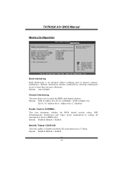
Memory interleaving increases bandwidth by turning off unoccupied or inactive DIMM slots. Options: Disabled (Default) / Enabled 39 Options: Disabled (Default) / Enabled MemClk Tristate C3/ATLVID T his ... Help F1 0 S ave and Exit ES C E xit vxx.xx (C)C opyright 198 5-200x, Amer ican Megatre nds, Inc. TA790GX A3+ BIOS Manual Memory Configuration Memor y Configurati on Bank Interleaving Chann el Interleavi ng Enabl e Clock to improve memory perform ance. Options: Auto (Default) Channel Interleaving T his item enables or disables the MemClk T ristate function in...
Memory interleaving increases bandwidth by turning off unoccupied or inactive DIMM slots. Options: Disabled (Default) / Enabled 39 Options: Disabled (Default) / Enabled MemClk Tristate C3/ATLVID T his ... Help F1 0 S ave and Exit ES C E xit vxx.xx (C)C opyright 198 5-200x, Amer ican Megatre nds, Inc. TA790GX A3+ BIOS Manual Memory Configuration Memor y Configurati on Bank Interleaving Chann el Interleavi ng Enabl e Clock to improve memory perform ance. Options: Auto (Default) Channel Interleaving T his item enables or disables the MemClk T ristate function in...
Bios Setup
Page 41
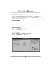
...hours. Options: Always (Default) / Auto Power Dow n Enable T his item allows you to enable or disable the remapping of ECC protection. TA790GX A3+ BIOS Manual Memory Hole Remapping T his item controls the DRAM power down function. Note: The Super ECC mode dynamically sets the DRAM scrub rate so all of... [Dis abled] [Dis abled] [Dis abled] [Dis abled] [Dis abled] [Dis abled] [Dis abled] Set the level of the overlapped PCI memory above the total physical memory. C hange Option F1 G eneral Help F10 S ave and Exit ESC E xit vxx .xx (C)Copyright 1985-200x, American Me gatrends, Inc. 40 ...
...hours. Options: Always (Default) / Auto Power Dow n Enable T his item allows you to enable or disable the remapping of ECC protection. TA790GX A3+ BIOS Manual Memory Hole Remapping T his item controls the DRAM power down function. Note: The Super ECC mode dynamically sets the DRAM scrub rate so all of... [Dis abled] [Dis abled] [Dis abled] [Dis abled] [Dis abled] [Dis abled] [Dis abled] Set the level of the overlapped PCI memory above the total physical memory. C hange Option F1 G eneral Help F10 S ave and Exit ESC E xit vxx .xx (C)Copyright 1985-200x, American Me gatrends, Inc. 40 ...

Bios Setup
Page 44
...iguration > Hyp er Transport Configuratio n > Mem ory Configura tion > EC Configuration GFX E ngine Clock O verride [ Disabled] Integ rated Memory Test [ Enabled] Options Enab led Disa bled S elect Screen S elect Item +- Main BIOS S ETUP UTILITY Advanced PCIPnP Boot Chips et ...Configura tion > EC Configuration GFX E ngine Clock O verride [ Disabled] Integ rated Memory Test [ Disabled] Options Enab led Disa bled S elect Screen S elect Item +- TA790GX A3+ BIOS Manual Integrated Memory Test Integrat ed Memory T est allows users to complete the test. C hange Option F1 G eneral ...
...iguration > Hyp er Transport Configuratio n > Mem ory Configura tion > EC Configuration GFX E ngine Clock O verride [ Disabled] Integ rated Memory Test [ Enabled] Options Enab led Disa bled S elect Screen S elect Item +- Main BIOS S ETUP UTILITY Advanced PCIPnP Boot Chips et ...Configura tion > EC Configuration GFX E ngine Clock O verride [ Disabled] Integ rated Memory Test [ Disabled] Options Enab led Disa bled S elect Screen S elect Item +- TA790GX A3+ BIOS Manual Integrated Memory Test Integrat ed Memory T est allows users to complete the test. C hange Option F1 G eneral ...
Setup Manual
Page 2
... 1: Introduction 1 1.1 Before You Start 1 1.2 Package Checklist 1 1.3 Motherboard Features 2 1.4 Rear Panel Connectors 3 1.5 Motherboard Layout 4 Chapter 2: Hardware Installation 5 2.1 Installing Central Processing Unit (CPU 5 2.2 FAN Headers 7 2.3 Installing System Memory 8 2.4 Connectors and Slots 10 Chapter 3: Headers & Jumpers Setup 13 3.1 How to Setup Jumpers 13 3.2 Detail Settings 13 Chapter 4: (Hybrid) CrossFireX Function 19 4.1 CrossFireX Requirements 19...
... 1: Introduction 1 1.1 Before You Start 1 1.2 Package Checklist 1 1.3 Motherboard Features 2 1.4 Rear Panel Connectors 3 1.5 Motherboard Layout 4 Chapter 2: Hardware Installation 5 2.1 Installing Central Processing Unit (CPU 5 2.2 FAN Headers 7 2.3 Installing System Memory 8 2.4 Connectors and Slots 10 Chapter 3: Headers & Jumpers Setup 13 3.1 How to Setup Jumpers 13 3.2 Detail Settings 13 Chapter 4: (Hybrid) CrossFireX Function 19 4.1 CrossFireX Requirements 19...
Setup Manual
Page 4
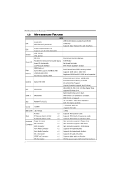
... Environment Control initiatives, H/W Monitor Fan Speed Controller ITE's "Smart Guardian" function Main Memory DIMM Slots x 4 Each DIMM supports 256MB/512MB/ 1GB/2GB/4GB DDR3 Max Memory Capicity 16GB Dual Channel Mode DDR3 memory module Supports DDR3 1333 / 1066 / 800 Registered DIMM and ECC DIMM is not supported... Graphics Radeon HD 3300 Onboard side port memory 128MB DDR2 Max Shared Video Memory is 512MB DX10/UVD/HDCP support (Hybrid) CrossFireX support (by ATI driver) IDE AMD SB750 Ultra DMA 33 / 66 / 100...
... Environment Control initiatives, H/W Monitor Fan Speed Controller ITE's "Smart Guardian" function Main Memory DIMM Slots x 4 Each DIMM supports 256MB/512MB/ 1GB/2GB/4GB DDR3 Max Memory Capicity 16GB Dual Channel Mode DDR3 memory module Supports DDR3 1333 / 1066 / 800 Registered DIMM and ECC DIMM is not supported... Graphics Radeon HD 3300 Onboard side port memory 128MB DDR2 Max Shared Video Memory is 512MB DX10/UVD/HDCP support (Hybrid) CrossFireX support (by ATI driver) IDE AMD SB750 Ultra DMA 33 / 66 / 100...
Setup Manual
Page 10
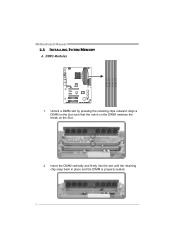
Insert the DIMM vertically and firmly into the slot until the retaining chip snap back in place and the DIMM is properly seated. 8 Unlock a DIMM slot by pressing the retaining clips outward. D D R 3_A1 D D R 3_B1 D D R 3_A2 D D R 3_B2 Motherboard Manual 2.3 INSTALLING SYSTEM MEMORY A. Align a DIMM on the slot such that the notch on the DIMM matches the break on the Slot. 2. DDR3 Modules 1.
Insert the DIMM vertically and firmly into the slot until the retaining chip snap back in place and the DIMM is properly seated. 8 Unlock a DIMM slot by pressing the retaining clips outward. D D R 3_A1 D D R 3_B1 D D R 3_A2 D D R 3_B2 Motherboard Manual 2.3 INSTALLING SYSTEM MEMORY A. Align a DIMM on the slot such that the notch on the DIMM matches the break on the Slot. 2. DDR3 Modules 1.

Setup Manual
Page 11
.../4GB 256MB/512MB/1GB/2GB/4GB 256MB/512MB/1GB/2GB/4GB 256MB/512MB/1GB/2GB/4GB Total Memory Size Max is 16GB. TA790GX A3+ B. Dual Channel Status DIMMA1 DIMMB1 DIMMA2 DIMMB2 Enabled O O X X Enabled X X O O Enabled O O O O (O means memory installed, X means memory not installed.) The DRAM bus width of the same density in pairs, shown in the table...
.../4GB 256MB/512MB/1GB/2GB/4GB 256MB/512MB/1GB/2GB/4GB 256MB/512MB/1GB/2GB/4GB Total Memory Size Max is 16GB. TA790GX A3+ B. Dual Channel Status DIMMA1 DIMMB1 DIMMA2 DIMMB2 Enabled O O X X Enabled X X O O Enabled O O O O (O means memory installed, X means memory not installed.) The DRAM bus width of the same density in pairs, shown in the table...
Setup Manual
Page 20
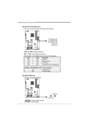
PWRSW1 RSTSW1 PWRSW1: Power Switch button. PHASE1_LED~PHASE4_LED ON OFF Phase Indicator Phase Active Phase Disable On-Board Buttons There are 6 LED indicators showing system status. Motherboard Manual On-Board LED Indicators There are 2 on-board buttons. RSTSW1: Reset button. 18 PHASE1_LED PHASE2_LED PHASE3_LED PHASE4_LED LED_D2 LED_D1 LED1 & LED2: Debug Indicators PH1 ~ PH4: Power Status Indicators Please refer to the tables below for specific messages: LED1 LED2 Message ON ON Normal ON OFF Memory Error OFF ON VGA Error OFF OFF Abnormal: CPU / Chipset error.
PWRSW1 RSTSW1 PWRSW1: Power Switch button. PHASE1_LED~PHASE4_LED ON OFF Phase Indicator Phase Active Phase Disable On-Board Buttons There are 6 LED indicators showing system status. Motherboard Manual On-Board LED Indicators There are 2 on-board buttons. RSTSW1: Reset button. 18 PHASE1_LED PHASE2_LED PHASE3_LED PHASE4_LED LED_D2 LED_D1 LED1 & LED2: Debug Indicators PH1 ~ PH4: Power Status Indicators Please refer to the tables below for specific messages: LED1 LED2 Message ON ON Normal ON OFF Memory Error OFF ON VGA Error OFF OFF Abnormal: CPU / Chipset error.
Setup Manual
Page 28
Motherboard Manual CHAPTER 6: T-SERIES BIOS & SOFTWARE 6.1 T-SERIES BIOS T-Series BIOS Features Overclocking Navigator Engine (O.N.E.) Memory Integration Test (M.I.T., under Overclock Navigator Engine) BIO-Flasher: Update BIOS file from this manual is being continuously updated. WARNING !! A. Change Option F1 General Help F10 ...
Motherboard Manual CHAPTER 6: T-SERIES BIOS & SOFTWARE 6.1 T-SERIES BIOS T-Series BIOS Features Overclocking Navigator Engine (O.N.E.) Memory Integration Test (M.I.T., under Overclock Navigator Engine) BIO-Flasher: Update BIOS file from this manual is being continuously updated. WARNING !! A. Change Option F1 General Help F10 ...


