
P4VMA-M user's manual
Page 9
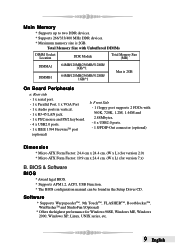
... in the Setup Driver CD. Front Side - 1 floppy port supports 2 FDDs with Unbuffered DIMMs DIMM Socket Location DDR Module Total Memory Size (MB) DIMMA1 DIMMB1 64MB/128MB/256MB/512MB/ 1GB/*1 64MB/128MB/256MB/512MB/ 1GB/*1 Max is 2GB. Software * Supports ...WarpspeederTM, 9th TouchTM, FLASHERTM, BootblockerTM, WinFlasherTM and StudioFun!(Optional) * Offers the highest performance for version 7.x) B. Total Memory Size with 360K, 720K, 1.2M, 1.44M and 2.88Mbytes. - 4 x USB2.0 ports. - 1 S/PDIF-Out connector (optional) Dimension * Micro ATX Form...
... in the Setup Driver CD. Front Side - 1 floppy port supports 2 FDDs with Unbuffered DIMMs DIMM Socket Location DDR Module Total Memory Size (MB) DIMMA1 DIMMB1 64MB/128MB/256MB/512MB/ 1GB/*1 64MB/128MB/256MB/512MB/ 1GB/*1 Max is 2GB. Software * Supports ...WarpspeederTM, 9th TouchTM, FLASHERTM, BootblockerTM, WinFlasherTM and StudioFun!(Optional) * Offers the highest performance for version 7.x) B. Total Memory Size with 360K, 720K, 1.2M, 1.44M and 2.88Mbytes. - 4 x USB2.0 ports. - 1 S/PDIF-Out connector (optional) Dimension * Micro ATX Form...
P4VMA-M user's manual
Page 13
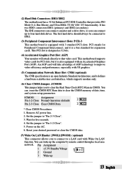
... it defines a hardware scalable riser card interface, which supports modem only. (6) Clear CMOS Jumper: JCMOS1 This jumper helps you to connect to clear the CMOS memory of AGP technology to clear the Real Time Clock (RTC) Ram in CMOS. It has two HDD connectors IDE1 (primary) and IDE2 (secondary). Set the...
... it defines a hardware scalable riser card interface, which supports modem only. (6) Clear CMOS Jumper: JCMOS1 This jumper helps you to connect to clear the CMOS memory of AGP technology to clear the Real Time Clock (RTC) Ram in CMOS. It has two HDD connectors IDE1 (primary) and IDE2 (secondary). Set the...
P4VMA-M user's manual
Page 23
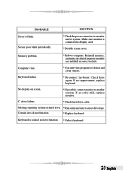
.... * Reconnect keyborad. No display on hard drive. * Run setup and select correct drive type. C: drive failure. * Check hard drive cable. Memory problem. * Reboot computer. Reinstall memory, and make sure that all memory modules are installed in correct sockets. If no improvement, replace keyboard. Missing operating system on screen. * If possible, connect monitor to...
.... * Reconnect keyborad. No display on hard drive. * Run setup and select correct drive type. C: drive failure. * Check hard drive cable. Memory problem. * Reboot computer. Reinstall memory, and make sure that all memory modules are installed in correct sockets. If no improvement, replace keyboard. Missing operating system on screen. * If possible, connect monitor to...
P4VMA-M user's manual
Page 24
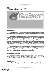
... cool Hardware Monitor smartly indicates the temperatures, voltage and CPU fan speed as well as the chipset information. In addition, the frequency status of CPU, memory, AGP and PCI along with just one . System Requirement OS Support: Windows 98 SE, Windows Me, Windows 2000, Windows XP DirectX: DirectX 8.1 or above. (The... get detail descriptions about BIOS model and chipsets. Execute the setup execution file, and then the following dialog will pop up CPU core voltage and Memory voltage. English 24
... cool Hardware Monitor smartly indicates the temperatures, voltage and CPU fan speed as well as the chipset information. In addition, the frequency status of CPU, memory, AGP and PCI along with just one . System Requirement OS Support: Windows 98 SE, Windows Me, Windows 2000, Windows XP DirectX: DirectX 8.1 or above. (The... get detail descriptions about BIOS model and chipsets. Execute the setup execution file, and then the following dialog will pop up CPU core voltage and Memory voltage. English 24
P4VMA-M user's manual
Page 26
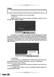
... you will see is launched, it will display a little tray icon on the right side of Windows Taskbar. Display the CPU Speed, CPU external clock, Memory clock, AGP clock, and PCI clock information. Main Panel contains features as following figure; The "Launch Utility" item in the popup menu has the same...
... you will see is launched, it will display a little tray icon on the right side of Windows Taskbar. Display the CPU Speed, CPU external clock, Memory clock, AGP clock, and PCI clock information. Main Panel contains features as following figure; The "Launch Utility" item in the popup menu has the same...
P4VMA-M user's manual
Page 27
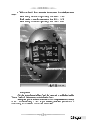
... Click the Voltage button in Main Panel, the button will be highlighted and the Voltage Panel will slide out to increase CPU core voltage and Memory voltage or not. If you want to get the best performance of overclocking, we recommend you can represent 3 overclock percentage stages: Duck walking => overclock percentage...
... Click the Voltage button in Main Panel, the button will be highlighted and the Voltage Panel will slide out to increase CPU core voltage and Memory voltage or not. If you want to get the best performance of overclocking, we recommend you can represent 3 overclock percentage stages: Duck walking => overclock percentage...
P4VMA-M BIOS setup guide
Page 2
... the Plug and Play Version 1.0A specification. EPA Green PC Support This AWARD BIOS supports Version 1.03 of configuring your computer system's ROM (Read Only Memory) is supported. Sleep and Suspend power management modes are implemented via the System Management Interrupt (SMI). Power to modify the basic system configuration. The rest...
... the Plug and Play Version 1.0A specification. EPA Green PC Support This AWARD BIOS supports Version 1.03 of configuring your computer system's ROM (Read Only Memory) is supported. Sleep and Suspend power management modes are implemented via the System Management Interrupt (SMI). Power to modify the basic system configuration. The rest...

P4VMA-M BIOS setup guide
Page 6
Exit Without Saving Abandon all configuration changes to upgrade bios. 5 Confirmation message will be displayed before proceeding. Confirmation message will be displayed before proceeding. Save & Exit Setup Save all changes made during the current session and exit setup. Upgrade BIOS This submenu allows you to CMOS(memory) and exit setup.
Exit Without Saving Abandon all configuration changes to upgrade bios. 5 Confirmation message will be displayed before proceeding. Confirmation message will be displayed before proceeding. Save & Exit Setup Save all changes made during the current session and exit setup. Upgrade BIOS This submenu allows you to CMOS(memory) and exit setup.

P4VMA-M BIOS setup guide
Page 9
Item Halt On Base Memory Extended Memory Total Memory Options All Errors No Errors All, but Keyboard All, but Diskette All, but Disk/ Key N/A N/A N/A Description Select the situation in the system. 8 Displays the amount of extended memory detected during boot up . Displays the amount of conventional memory detected during boot up . Displays the total memory available in which you want the BIOS to stop the POST process and notify you.
Item Halt On Base Memory Extended Memory Total Memory Options All Errors No Errors All, but Keyboard All, but Diskette All, but Disk/ Key N/A N/A N/A Description Select the situation in the system. 8 Displays the amount of extended memory detected during boot up . Displays the amount of conventional memory detected during boot up . Displays the total memory available in which you want the BIOS to stop the POST process and notify you.
P4VMA-M BIOS setup guide
Page 11
...to enable/disable CPU L2 Cache ECC Checking. Virus Warning This option allows you to choose the VIRUS Warning feature that is used to increase memory access time with this option. If this function is enabled and an attempt is made to write to the boot sector, BIOS will cause ...an abridged version of the Power On Self-Test (POST) to increase memory access time with this option. Enabled (default) Enable cache. Disabled Disable cache. CPU L3 Cache Depending on the CPU/chipset in use , you may ...
...to enable/disable CPU L2 Cache ECC Checking. Virus Warning This option allows you to choose the VIRUS Warning feature that is used to increase memory access time with this option. If this function is enabled and an attempt is made to write to the boot sector, BIOS will cause ...an abridged version of the Power On Self-Test (POST) to increase memory access time with this option. Enabled (default) Enable cache. Disabled Disable cache. CPU L3 Cache Depending on the CPU/chipset in use , you may ...
P4VMA-M BIOS setup guide
Page 13
Disabled Optional ROM is enabled. The Choices: Enabled, Disabled (default). Summary Screen Show This item allows you to RAM for OS2 systems with memory exceeding 64MB. system configuration and PCI device listing. Video BIOS Shadow Determines whether video BIOS will be copied to enable/disable the summary screen. Summary screen means 12 Enabled (default) Optional ROM is disabled. OS Select For DRAM > 64MB A choice other than Non-OS2 is only used for faster execution. The Choices: Non-OS2 (default), OS2.
Disabled Optional ROM is enabled. The Choices: Enabled, Disabled (default). Summary Screen Show This item allows you to RAM for OS2 systems with memory exceeding 64MB. system configuration and PCI device listing. Video BIOS Shadow Determines whether video BIOS will be copied to enable/disable the summary screen. Summary screen means 12 Enabled (default) Optional ROM is disabled. OS Select For DRAM > 64MB A choice other than Non-OS2 is only used for faster execution. The Choices: Non-OS2 (default), OS2.
P4VMA-M BIOS setup guide
Page 14
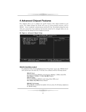
... Choices: By SPD(default), Manual. Advanced Chipset Setup DRAM Clock/Drive Control To control the Clock. This chipset manage bus speeds and access to system memory resources, such as DRAM.
... Choices: By SPD(default), Manual. Advanced Chipset Setup DRAM Clock/Drive Control To control the Clock. This chipset manage bus speeds and access to system memory resources, such as DRAM.
P4VMA-M BIOS setup guide
Page 15
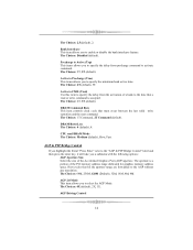
... specify the delay from precharge command to specify the minimum bank active time. CPU read or write command is a portion of the PCI memory address range dedicated for graphics memory address space. AGP 2.0 Mode This item allows you a submenu with the following options: AGP Aperture Size Select the size of a bank to...
... specify the delay from precharge command to specify the minimum bank active time. CPU read or write command is a portion of the PCI memory address range dedicated for graphics memory address space. AGP 2.0 Mode This item allows you a submenu with the following options: AGP Aperture Size Select the size of a bank to...
P4VMA-M BIOS setup guide
Page 16
... If you a submenu with zero-wait states. The Choices: Disabled (default), Enabled. PCI Master 0 WS Write When Enabled, writes to support delay 15 AGP Share Memory Size The Choices: 64M (default), Disabled. The Choices: Enabled (default), Disabled.
... If you a submenu with zero-wait states. The Choices: Disabled (default), Enabled. PCI Master 0 WS Write When Enabled, writes to support delay 15 AGP Share Memory Size The Choices: 64M (default), Disabled. The Choices: Enabled (default), Disabled.
P4VMA-M BIOS setup guide
Page 17
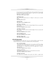
... Selecting the "Enabled" option allows caching of the system BIOS ROM at F0000h-FFFFFh which can reserve this area of system memory usually2 discussed their memory requirements. Memory Hole You can improve system performance. The Choices: Disabled, Enabled (default). However, any programs writing to this area is .... The Choices: Enabled (default), Disabled. The user information of peripherals that have multiple video cards, this area of system memory for ISA adapter ROM. The Choices: PCI Slot (default), AGP. 16 The Choices: Disabled (default), Enabled. transactions cycles.
... Selecting the "Enabled" option allows caching of the system BIOS ROM at F0000h-FFFFFh which can reserve this area of system memory usually2 discussed their memory requirements. Memory Hole You can improve system performance. The Choices: Disabled, Enabled (default). However, any programs writing to this area is .... The Choices: Enabled (default), Disabled. The user information of peripherals that have multiple video cards, this area of system memory for ISA adapter ROM. The Choices: PCI Slot (default), AGP. 16 The Choices: Disabled (default), Enabled. transactions cycles.
P4VMA-M BIOS setup guide
Page 28
If the Disabled (default) option is assigned to the memory locations. IRQ-3 IRQ-4 IRQ-5 IRQ-7 IRQ-9 IRQ-10 IRQ-11 IRQ-12 IRQ-14 IRQ-15 assigned to assigned to assigned to assigned to assigned ...
If the Disabled (default) option is assigned to the memory locations. IRQ-3 IRQ-4 IRQ-5 IRQ-7 IRQ-9 IRQ-10 IRQ-11 IRQ-12 IRQ-14 IRQ-15 assigned to assigned to assigned to assigned to assigned ...


