Setup Manual
Page 3
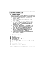
... the rear side of the board unless necessary. Before you start installing the motherboard, please make sure you follow the instructions below: „ Prepare a dry and stable working environment with sufficient lighting. „ Always disconnect ... ATX Case X 1 Installation Guide X 1 Fully Setup Driver CD X 1 (full version manual files inside the case after installation. CHAPTER 1: INTRODUCTION MCP6PB M2+ 1.1 BEFORE YOU START Thank you take the motherboard out from dangerous area, such as heat source, humid air and water. 1.2 PACKAGE CHECKLIST IDE Cable X 1 Serial ATA Cable X 1 Rear I/O...
... the rear side of the board unless necessary. Before you start installing the motherboard, please make sure you follow the instructions below: „ Prepare a dry and stable working environment with sufficient lighting. „ Always disconnect ... ATX Case X 1 Installation Guide X 1 Fully Setup Driver CD X 1 (full version manual files inside the case after installation. CHAPTER 1: INTRODUCTION MCP6PB M2+ 1.1 BEFORE YOU START Thank you take the motherboard out from dangerous area, such as heat source, humid air and water. 1.2 PACKAGE CHECKLIST IDE Cable X 1 Serial ATA Cable X 1 Rear I/O...
Setup Manual
Page 11
Memory Capacity DIMM Socket Location DDR2 Module DIMMA1 256MB/512MB/1GB/2GB DIMMB1 256MB/512MB/1GB/2GB MCP6PB M2+ Total Memory Size Max is 4GB. Dual Channel Status DIMMA1 DIMMB1 Disabled O X Disabled X O Enabled O O (O means memory installed, X means memory not installed.) The DRAM bus width ... Channel Memory installation To trigger the Dual Channel function of the same density in pairs, shown in the following requirements: Install memory module of the motherboard, the memory module must be the same (x8 or x16) 9 B.
Memory Capacity DIMM Socket Location DDR2 Module DIMMA1 256MB/512MB/1GB/2GB DIMMB1 256MB/512MB/1GB/2GB MCP6PB M2+ Total Memory Size Max is 4GB. Dual Channel Status DIMMA1 DIMMB1 Disabled O X Disabled X O Enabled O O (O means memory installed, X means memory not installed.) The DRAM bus width ... Channel Memory installation To trigger the Dual Channel function of the same density in pairs, shown in the following requirements: Install memory module of the motherboard, the memory module must be the same (x8 or x16) 9 B.
Setup Manual
Page 13
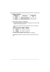
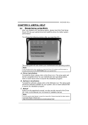
PCI-Express supports a raw bit-rate of 8GB/s totally. - PCI1 11 PEX16_1 PCI1: Peripheral Component Interconnect Slot This motherboard is a bus standard for expansion cards. PCI-Express 1.0a compliant. - Maximum theoretical realized bandwidth of 4GB/s simultaneously per direction, for Peripheral Component Interconnect, and it is equipped with 1 standard PCI slot. PCI stands for an aggregate of 2.5Gb/s on the data pins. - 2X bandwidth over the traditional PCI architecture. MCP6PB M2+ PEX16_1: PCI-Express Gen2 x16 Slot - This PCI slot is designated as 32 bits.
PCI-Express supports a raw bit-rate of 8GB/s totally. - PCI1 11 PEX16_1 PCI1: Peripheral Component Interconnect Slot This motherboard is a bus standard for expansion cards. PCI-Express 1.0a compliant. - Maximum theoretical realized bandwidth of 4GB/s simultaneously per direction, for Peripheral Component Interconnect, and it is equipped with 1 standard PCI slot. PCI stands for an aggregate of 2.5Gb/s on the data pins. - 2X bandwidth over the traditional PCI architecture. MCP6PB M2+ PEX16_1: PCI-Express Gen2 x16 Slot - This PCI slot is designated as 32 bits.
Setup Manual
Page 17
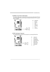
MCP6PB M2+ JAUDIOF: Front Panel Audio Header This header allows user to send 9 Ring indicator 10 NC 15 AC'97 connector is not acceptable. 2 10 Pin Assignment 1 ... in 2 Ground 3 Mic Right in 4 GPIO 5 Right line in 6 Jack Sense 7 Front Sense 8 Key 9 Left line in 10 Jack Sense 1 9 JCOM: Serial port Connector The motherboard has a Serial Port Connector for connecting RS-232 Port. 2 10 1 9 Pin Assignment 1 Carrier detect 2 Received data 3 Transmitted data 4 Data terminal ready 5 Signal ground 6 Data set...
MCP6PB M2+ JAUDIOF: Front Panel Audio Header This header allows user to send 9 Ring indicator 10 NC 15 AC'97 connector is not acceptable. 2 10 Pin Assignment 1 ... in 2 Ground 3 Mic Right in 4 GPIO 5 Right line in 6 Jack Sense 7 Front Sense 8 Key 9 Left line in 10 Jack Sense 1 9 JCOM: Serial port Connector The motherboard has a Serial Port Connector for connecting RS-232 Port. 2 10 1 9 Pin Assignment 1 Carrier detect 2 Received data 3 Transmitted data 4 Data terminal ready 5 Signal ground 6 Data set...
Setup Manual
Page 23
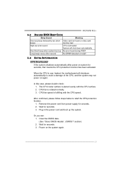
...also provide manual in the Driver CD. The setup guide will need Acrobat Reader to locate and execute the file SETUP.EXE under your motherboard and operating system. Driver Installation To install the driver, please click on each software title to launch the installation program. C. Note:... Aside from http://www.adobe.com /produ cts/a crobat /reads tep2 .html 21 B. Click on the Software icon. CHAPTER 5: USEFUL HELP MCP6PB M2+ 5.1 DRIVER INSTALLATION NOTE After you installed your operating system, please insert the Fully Setup Driver CD into your system, click on each device ...
...also provide manual in the Driver CD. The setup guide will need Acrobat Reader to locate and execute the file SETUP.EXE under your motherboard and operating system. Driver Installation To install the driver, please click on each software title to launch the installation program. C. Note:... Aside from http://www.adobe.com /produ cts/a crobat /reads tep2 .html 21 B. Click on the Software icon. CHAPTER 5: USEFUL HELP MCP6PB M2+ 5.1 DRIVER INSTALLATION NOTE After you installed your operating system, please insert the Fully Setup Driver CD into your system, click on each device ...
Setup Manual
Page 25
...surface. 2. Wait for seconds. 2. Clear the CMOS data. (See "Close CMOS Header: JCMOS1" section) 2. The CPU cooler surface is over heated, the motherboard will shut down automatically One Short beep when system boot-up the system. Remove the power cord from power supply for seconds. 3. When the CPU... After confirmed, please follow steps below to avoid a damage of the CPU, and the system may not power on the system again. 23 MCP6PB M2+ 5.3 AWARD BIOS BEEP CODE Beep Sound Meaning One long beep followed by two short Video card not found or video card beeps memory bad High...
...surface. 2. Wait for seconds. 2. Clear the CMOS data. (See "Close CMOS Header: JCMOS1" section) 2. The CPU cooler surface is over heated, the motherboard will shut down automatically One Short beep when system boot-up the system. Remove the power cord from power supply for seconds. 3. When the CPU... After confirmed, please follow steps below to avoid a damage of the CPU, and the system may not power on the system again. 23 MCP6PB M2+ 5.3 AWARD BIOS BEEP CODE Beep Sound Meaning One long beep followed by two short Video card not found or video card beeps memory bad High...
Bios Manual
Page 2
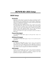
... settings in the Phoenix-Award™ BIOS Setup program on this motherboard. The power of CMOS RAM is supplied by this PHOENIX-AWARD BIOS. Power to the hard disk drives and video monitors can do without accessing programs from a disk. MCP6PB M2+ BIOS Setup BIOS Setup Introduction The purpose of this manual is...
... settings in the Phoenix-Award™ BIOS Setup program on this motherboard. The power of CMOS RAM is supplied by this PHOENIX-AWARD BIOS. Power to the hard disk drives and video monitors can do without accessing programs from a disk. MCP6PB M2+ BIOS Setup BIOS Setup Introduction The purpose of this manual is...

Bios Manual
Page 19
... disable RAID function. Select "Enabled" to enable or disable SATA Primary/Secondary RAID. The Choices: Disabled (default), Enabled. On-chip IDE Channel 0 The motherboard chipset contains a PCI IDE interface with support for two IDE channels. The Choices: Enabled (default), Disabled. Select "Disabled" to deactivate an interface if you... for each of the IDE devices that the onboard IDE interface supports. The Choices: Auto (default), Mode0, Mode1, Mode2, Mode3, Mode4. 19 MCP6PB M2+ BIOS Setup RAID Config RAID Enable This option allows you set a PIO mode (0-4) for each device.
... disable RAID function. Select "Enabled" to enable or disable SATA Primary/Secondary RAID. The Choices: Disabled (default), Enabled. On-chip IDE Channel 0 The motherboard chipset contains a PCI IDE interface with support for two IDE channels. The Choices: Enabled (default), Disabled. Select "Disabled" to deactivate an interface if you... for each of the IDE devices that the onboard IDE interface supports. The Choices: Auto (default), Mode0, Mode1, Mode2, Mode3, Mode4. 19 MCP6PB M2+ BIOS Setup RAID Config RAID Enable This option allows you set a PIO mode (0-4) for each device.


