Update Manual
Page 1
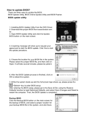
... your backup BIOS file in the system. There are three ways to start the BIOS update. Click Yes to update the BIOS: BIOS Update Utility, BIOS Online Update Utility and BIOS Flasher. Choose the location for your BIOS file in the system, and click Save. After entering the BIOS setup, please go to the Save & Exit, using the Restore Defaults function to load Optimized Defaults, and select Save Changes and Reset to restart the computer. tw . 3. BIOS update utility 1.
... your backup BIOS file in the system. There are three ways to start the BIOS update. Click Yes to update the BIOS: BIOS Update Utility, BIOS Online Update Utility and BIOS Flasher. Choose the location for your BIOS file in the system, and click Save. After entering the BIOS setup, please go to the Save & Exit, using the Restore Defaults function to load Optimized Defaults, and select Save Changes and Reset to restart the computer. tw . 3. BIOS update utility 1.
Update Manual
Page 2
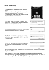
... download it. Click Yes to start the BIOS update. After the download is connected to the internet before using the Restore Defaults function to load Optimized Defaults, and select Save Changes and Reset to program (update) the BIOS or not. After the updating process is completed. Open BIOS Update Utility and click the Online Update button on the main screen. 4. After entering the BIOS setup, please go to enter BIOS setup. Online Update Utility 1. Click Yes to proceed. 6. Installing BIOS Update Utility from the DVD Driver...
... download it. Click Yes to start the BIOS update. After the download is connected to the internet before using the Restore Defaults function to load Optimized Defaults, and select Save Changes and Reset to program (update) the BIOS or not. After the updating process is completed. Open BIOS Update Utility and click the Online Update button on the main screen. 4. After entering the BIOS setup, please go to enter BIOS setup. Online Update Utility 1. Click Yes to proceed. 6. Installing BIOS Update Utility from the DVD Driver...
Update Manual
Page 3
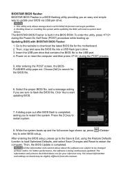
... the software are for your BIOS via USB pen drive. 1. Press the [Y] key to the USB port. 4. Then, copy and save the BIOS file into a USB flash (pen) drive. 3. Click Yes to restart the computer. Power on board may be changed without notice. After entering the BIOS setup, please go to the Save & Exit, using the Restore Defaults function to load Optimized Defaults, and select Save Changes and Reset to start updating BIOS. 7. Shutting down or resetting the...
... the software are for your BIOS via USB pen drive. 1. Press the [Y] key to the USB port. 4. Then, copy and save the BIOS file into a USB flash (pen) drive. 3. Click Yes to restart the computer. Power on board may be changed without notice. After entering the BIOS setup, please go to the Save & Exit, using the Restore Defaults function to load Optimized Defaults, and select Save Changes and Reset to start updating BIOS. 7. Shutting down or resetting the...
Setup Manual
Page 4
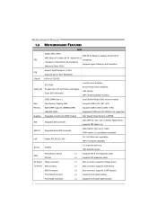
... Max Shared Video Memory is 256MB IDE Integrated IDE Controller Ultra DMA 33 / 66 / 100 / 133 Bus Master Mode supports PIO Mode 0~4, SATA II Integrated Serial ATA Controller Data transfer rates up to 3 Gb/s SATA Version 2.0 specification compliant LAN Realtek RTL 8201CL PHY 10 / 100 Mb/s auto negotiation Half / Full duplex capability Sound ALC662 5.1 channels audio out High Definition Audio Slots PCI Express x16 slot PCI slot x1 Supports PCI-E x16 expansion cards x1 Supports PCI expansion cards On Board Floppy connector x1 Each connector supports 2 Floppy drives Connector...
... Max Shared Video Memory is 256MB IDE Integrated IDE Controller Ultra DMA 33 / 66 / 100 / 133 Bus Master Mode supports PIO Mode 0~4, SATA II Integrated Serial ATA Controller Data transfer rates up to 3 Gb/s SATA Version 2.0 specification compliant LAN Realtek RTL 8201CL PHY 10 / 100 Mb/s auto negotiation Half / Full duplex capability Sound ALC662 5.1 channels audio out High Definition Audio Slots PCI Express x16 slot PCI slot x1 Supports PCI-E x16 expansion cards x1 Supports PCI expansion cards On Board Floppy connector x1 Each connector supports 2 Floppy drives Connector...
Setup Manual
Page 5
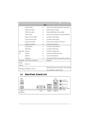
... Fan header System Fan header CMOS clear header USB connector Power Connector (24pin) Power Connector (4pin) Printer Port Connector Serial port Connector PS/2 Keyboard PS/2 Mouse Back Panel VGA port I/O LAN port USB Port Audio Jack Board Size 170 mm(W) x 235 mm(L) Special Features RAID 0 / 1 OS Support Windows XP / Vista / 7 MCP6PB M2+ SPEC x1 CPU Fan power supply (with Smart Fan function) x1 System Fan Power supply x1 Restore CMOS data to factory default x2 Each connector supports 2 front panel USB ports x1 Connects to Power supply x1 Connects to Power supply...
... Fan header System Fan header CMOS clear header USB connector Power Connector (24pin) Power Connector (4pin) Printer Port Connector Serial port Connector PS/2 Keyboard PS/2 Mouse Back Panel VGA port I/O LAN port USB Port Audio Jack Board Size 170 mm(W) x 235 mm(L) Special Features RAID 0 / 1 OS Support Windows XP / Vista / 7 MCP6PB M2+ SPEC x1 CPU Fan power supply (with Smart Fan function) x1 System Fan Power supply x1 Restore CMOS data to factory default x2 Each connector supports 2 front panel USB ports x1 Connects to Power supply x1 Connects to Power supply...
Setup Manual
Page 14
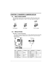
... Panel Header This 16-pin connector includes Power-on pins, the jumper is "close", if not, that means the jumper is placed on , Reset, HDD LED, Power LED, Sleep, and speaker connection. It allows user to set up jumpers. PWR_LED On/Off ++ - 9 16 1 +- 8 SPK RST HLED Pin Assignment 1 +5V 2 N/A 3 N/A 4 Speaker 5 HDD LED (+) 6 HDD LED (-) 7 Ground 8 Reset control Function Pin 9 Speaker 10 Connector 11 12 Hard drive 13 LED 14 Reset button 15 16 Assignment N/A N/A N/A Power LED (+) Power LED (+) Power LED (-) Power button Ground Function N/A N/A Power LED Power...
... Panel Header This 16-pin connector includes Power-on pins, the jumper is "close", if not, that means the jumper is placed on , Reset, HDD LED, Power LED, Sleep, and speaker connection. It allows user to set up jumpers. PWR_LED On/Off ++ - 9 16 1 +- 8 SPK RST HLED Pin Assignment 1 +5V 2 N/A 3 N/A 4 Speaker 5 HDD LED (+) 6 HDD LED (-) 7 Ground 8 Reset control Function Pin 9 Speaker 10 Connector 11 12 Hard drive 13 LED 14 Reset button 15 16 Assignment N/A N/A N/A Power LED (+) Power LED (+) Power LED (-) Power button Ground Function N/A N/A Power LED Power...
Setup Manual
Page 25
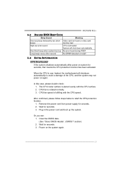
.... CPU fan is fulfilling with the CPU surface. 2. Remove the power cord from power supply for seconds. 3. Plug in the power cord and boot up No error found or video card beeps memory bad High-low siren sound CPU overheated System will shutdown automatically to relief the CPU protection function. 1. Wait for seconds. 2. MCP6PB M2+ 5.3 AWARD BIOS BEEP CODE Beep Sound Meaning One long beep followed by two short Video card not found during POST Long beeps every other second No DRAM detected or install...
.... CPU fan is fulfilling with the CPU surface. 2. Remove the power cord from power supply for seconds. 3. Plug in the power cord and boot up No error found or video card beeps memory bad High-low siren sound CPU overheated System will shutdown automatically to relief the CPU protection function. 1. Wait for seconds. 2. MCP6PB M2+ 5.3 AWARD BIOS BEEP CODE Beep Sound Meaning One long beep followed by two short Video card not found during POST Long beeps every other second No DRAM detected or install...
Setup Manual
Page 26
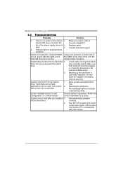
... cannot boot after user installs a 1. work 3. Indicator light on , power indicator lights are lit, the DIMM, press down at any time. Set master/slave jumpers correctly. Call the drive manufacturers for compatibility with other drives. 24 All hard disks are on keyboard does not shine. fails to disk controller board. Back up the hard drive is Power LED does not shine; Run SETUP program and select correct drive types. the securely plugged in the standard CMOS setup. Keyboard lights Using even...
... cannot boot after user installs a 1. work 3. Indicator light on , power indicator lights are lit, the DIMM, press down at any time. Set master/slave jumpers correctly. Call the drive manufacturers for compatibility with other drives. 24 All hard disks are on keyboard does not shine. fails to disk controller board. Back up the hard drive is Power LED does not shine; Run SETUP program and select correct drive types. the securely plugged in the standard CMOS setup. Keyboard lights Using even...
Bios Manual
Page 2
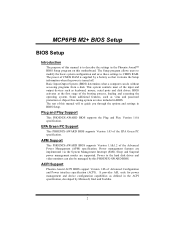
... guide you through the options and settings in the Phoenix-Award™ BIOS Setup program on this motherboard. This system controls most of Advanced Configuration and Power interface specification (ACPI). It provides ASL code for power management and device configuration capabilities as keyboard, mouse, serial ports and disk drives. ACPI Support Phoenix-Award ACPI BIOS support Version 1.0b of the input and output devices such as defined in BIOS. Plug and Play Support This PHOENIX-AWARD BIOS supports the Plug and Play Version 1.0A spec ification. The power of CMOS RAM...
... guide you through the options and settings in the Phoenix-Award™ BIOS Setup program on this motherboard. This system controls most of Advanced Configuration and Power interface specification (ACPI). It provides ASL code for power management and device configuration capabilities as keyboard, mouse, serial ports and disk drives. ACPI Support Phoenix-Award ACPI BIOS support Version 1.0b of the input and output devices such as defined in BIOS. Plug and Play Support This PHOENIX-AWARD BIOS supports the Plug and Play Version 1.0A spec ification. The power of CMOS RAM...
Bios Manual
Page 12
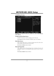
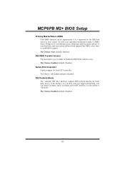
.... Slave, USB-CDROM0, USB-CDROM1. The Choices: Removable, Hard Disk, CDROM, Legacy LAN, Disabled. Disabling this order. The Choices: Enabled (default), Disabled. 12 The Choices: Enabled (default), Disabled Boot Up Floppy Seek When enabled, System will attempt to load the operating system in this option reduces the time it failed to load from the three devices above. MCP6PB M2+ BIOS Setup CD-ROM Boot Priority TheChoices: Pri. First/Second/Third Boot Device The BIOS will test the floppy drives to boot-up...
.... Slave, USB-CDROM0, USB-CDROM1. The Choices: Removable, Hard Disk, CDROM, Legacy LAN, Disabled. Disabling this order. The Choices: Enabled (default), Disabled. 12 The Choices: Enabled (default), Disabled Boot Up Floppy Seek When enabled, System will attempt to load the operating system in this option reduces the time it failed to load from the three devices above. MCP6PB M2+ BIOS Setup CD-ROM Boot Priority TheChoices: Pri. First/Second/Third Boot Device The BIOS will test the floppy drives to boot-up...
Bios Manual
Page 14
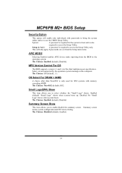
... configuration and PCI device listing. Setup (default): A password is also required to access the Setup Utility. APIC MODE Selecting Enabled enables APIC device mode reporting from the Setup main menu. The Choices: Enabled (default), Disabled. Enabled (default) "Small Logo" shows when system boots up. MCP6PB M2+ BIOS Setup Security Option This option will only apply if passwords are set from the BIOS to the operating system. Select version supported by the operation system running on this computer. The Choices: Non-OS2 (default), OS2. MPS Version Control...
... configuration and PCI device listing. Setup (default): A password is also required to access the Setup Utility. APIC MODE Selecting Enabled enables APIC device mode reporting from the Setup main menu. The Choices: Enabled (default), Disabled. Enabled (default) "Small Logo" shows when system boots up. MCP6PB M2+ BIOS Setup Security Option This option will only apply if passwords are set from the BIOS to the operating system. Select version supported by the operation system running on this computer. The Choices: Non-OS2 (default), OS2. MPS Version Control...

Bios Manual
Page 15
The default settings that came with the PCI bus. PCIE / SATA Spread Spectrum This item allows you to choose the frame buffer size of the chipset installed on -chip VGA. GPU Bank Flip The Choices: Disabled (default), Enabled. MCP6PB M2+ BIOS Setup 4 Advanced Chipset Features This submenu allows you to configure the specific features of on your system have been optimized and therefore should not be changed unless you are suspicious...
The default settings that came with the PCI bus. PCIE / SATA Spread Spectrum This item allows you to choose the frame buffer size of the chipset installed on -chip VGA. GPU Bank Flip The Choices: Disabled (default), Enabled. MCP6PB M2+ BIOS Setup 4 Advanced Chipset Features This submenu allows you to configure the specific features of on your system have been optimized and therefore should not be changed unless you are suspicious...

Bios Manual
Page 16
... function. The Choices: Auto (default), Disabled. 16 AMD K8 Cool&Quiet control The item allows you select K8 Cool'n'Quiet control. The Choices: Enabled (default), Disabled. CPU Feature Virtualization Virtualization Technology can virtually separate your system resource into several parts, thus enhance the performance when running virtual machines or multi interface systems. The Choices: Enabled (default), Disabled. MCP6PB M2+ BIOS Setup HT Spread Spectrum This item allows you to enable/disable SSE/SSE2 instruction.
... function. The Choices: Auto (default), Disabled. 16 AMD K8 Cool&Quiet control The item allows you select K8 Cool'n'Quiet control. The Choices: Enabled (default), Disabled. CPU Feature Virtualization Virtualization Technology can virtually separate your system resource into several parts, thus enhance the performance when running virtual machines or multi interface systems. The Choices: Enabled (default), Disabled. MCP6PB M2+ BIOS Setup HT Spread Spectrum This item allows you to enable/disable SSE/SSE2 instruction.

Bios Manual
Page 19
...: Auto (default), Mode0, Mode1, Mode2, Mode3, Mode4. 19 On-chip IDE Channel 0 The motherboard chipset contains a PCI IDE interface with support for each of the IDE devices that the onboard IDE interface supports. The Choices: Disabled (default), Enabled. Primary Master/Slave PIO The IDE PIO (Programmed Input / Output) fields let you are going to install a primary and/or secondary add-in IDE interface. MCP6PB M2+ BIOS Setup RAID Config RAID Enable This option allows you to enable or disable SATA Primary...
...: Auto (default), Mode0, Mode1, Mode2, Mode3, Mode4. 19 On-chip IDE Channel 0 The motherboard chipset contains a PCI IDE interface with support for each of the IDE devices that the onboard IDE interface supports. The Choices: Disabled (default), Enabled. Primary Master/Slave PIO The IDE PIO (Programmed Input / Output) fields let you are going to install a primary and/or secondary add-in IDE interface. MCP6PB M2+ BIOS Setup RAID Config RAID Enable This option allows you to enable or disable SATA Primary...
Bios Manual
Page 20
... Enabled (default), Disabled IDE Prefetch Mode The "onboard" IDE drive interfaces supports IDE prefetch function for Serial-ATA controller. The Choices: Enabled (default), Disabled. The Choices: Enabled (default), Disabled. 20 MCP6PB M2+ BIOS Setup Primary Master/Slave UDMA Ultra DMA function can be implemented if it is supported by the IDE hard drives in IDE interface, set this option to "Disab led". If the interface on your operating environment requires a DMA driver (Windows 95 or OSR2may need a third party IDE bus master driver...
... Enabled (default), Disabled IDE Prefetch Mode The "onboard" IDE drive interfaces supports IDE prefetch function for Serial-ATA controller. The Choices: Enabled (default), Disabled. The Choices: Enabled (default), Disabled. 20 MCP6PB M2+ BIOS Setup Primary Master/Slave UDMA Ultra DMA function can be implemented if it is supported by the IDE hard drives in IDE interface, set this option to "Disab led". If the interface on your operating environment requires a DMA driver (Windows 95 or OSR2may need a third party IDE bus master driver...

Bios Manual
Page 22
... has a floppy disk controller (FDC) installed on the system board and you to control the onboard MAC Media Interface. The Choices: Disabled (default), Enabled. The Choices: Enabled (default), Disabled. 22 MCP6PB M2+ BIOS Setup MAC Media Interface This option allows you wish to use it. If you to enable or disable the Onboard LAN Boot ROM. The Choices: Pin Strap (default), MII, RGMII Onboard LAN Boot ROM This item allows you installed another FDC or the system uses no floppy drive, select disabled in...
... has a floppy disk controller (FDC) installed on the system board and you to control the onboard MAC Media Interface. The Choices: Disabled (default), Enabled. The Choices: Enabled (default), Disabled. 22 MCP6PB M2+ BIOS Setup MAC Media Interface This option allows you wish to use it. If you to enable or disable the Onboard LAN Boot ROM. The Choices: Pin Strap (default), MII, RGMII Onboard LAN Boot ROM This item allows you installed another FDC or the system uses no floppy drive, select disabled in...
Bios Manual
Page 26
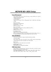
... 1 min. HDD Power Down When enabled, the hard-disk drives will cause the system to turn off the vertical and horizontal synchronization ports and write blanks to set time of which ranges from 1 min. Power Saving Maximum power management only available for HDD Power Down which have fixed mode settings Min. User Define (default) Allow you to the video buffer. HDD Power Down. 2. Suspend Mode = 1 hr. to 1 hr. All other devices remain...
... 1 min. HDD Power Down When enabled, the hard-disk drives will cause the system to turn off the vertical and horizontal synchronization ports and write blanks to set time of which ranges from 1 min. Power Saving Maximum power management only available for HDD Power Down which have fixed mode settings Min. User Define (default) Allow you to the video buffer. HDD Power Down. 2. Suspend Mode = 1 hr. to 1 hr. All other devices remain...
Bios Manual
Page 30
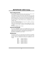
... the PCI Bus or provides for the resources controlled by function. These locations are no IRQ/DMA and I/O port conflicts. Legacy is the term, which resources are assigned to the memory locations. If the Enabled option is chosen, the system is forced to update ESCDs and then is set to the ISA Bus and provides non-PnP ISA add-on cards. Every peripheral device has...
... the PCI Bus or provides for the resources controlled by function. These locations are no IRQ/DMA and I/O port conflicts. Legacy is the term, which resources are assigned to the memory locations. If the Enabled option is chosen, the system is forced to update ESCDs and then is set to the ISA Bus and provides non-PnP ISA add-on cards. Every peripheral device has...

Bios Manual
Page 33
... H/W Monitor in POST If you to work under Windows 98 ACPI mode. PWM Duty Start CPU fan starts to set value, FAN will work under smart fan function when arrive this item and then the BIOS will show CPU fan speed. Start PWM Value When CPU temperature arrives to control the CPU Fan. This item is only effective under Smart Fan Function mode. The Choices: Disabled (default), Auto, 4-pin, 3-pin.. CPU Vcore, Chipset Volt, +3.3V, +5.0V, +12.0V, DDR/HT Voltage, 5V (SB), Voltage Battery Detect the system's voltage...
... H/W Monitor in POST If you to work under Windows 98 ACPI mode. PWM Duty Start CPU fan starts to set value, FAN will work under smart fan function when arrive this item and then the BIOS will show CPU fan speed. Start PWM Value When CPU temperature arrives to control the CPU Fan. This item is only effective under Smart Fan Function mode. The Choices: Disabled (default), Auto, 4-pin, 3-pin.. CPU Vcore, Chipset Volt, +3.3V, +5.0V, +12.0V, DDR/HT Voltage, 5V (SB), Voltage Battery Detect the system's voltage...

Bios Manual
Page 38
MCP6PB M2+ BIOS Setup Memory Hole Remapping The Choices: Enabled (default), Disabled. Auto Optimize Bottom IO The Choices: Enabled (default), Disabled. Bottom of [31:24] IO space The Choices: Min=0000 Max=00FF; Key in a HEX number. Precharge Time The Choices: 3 clocks (default), 2 clocks. Trfc0 for DIMM1 The Choices: 75ns (default) , 105ns, 127.5ns, 195ns, 327.5ns. Trfc1 for DIMM0 The Choices: 75ns (default), 105ns, 127.5ns, 195ns...
MCP6PB M2+ BIOS Setup Memory Hole Remapping The Choices: Enabled (default), Disabled. Auto Optimize Bottom IO The Choices: Enabled (default), Disabled. Bottom of [31:24] IO space The Choices: Min=0000 Max=00FF; Key in a HEX number. Precharge Time The Choices: 3 clocks (default), 2 clocks. Trfc0 for DIMM1 The Choices: 75ns (default) , 105ns, 127.5ns, 195ns, 327.5ns. Trfc1 for DIMM0 The Choices: 75ns (default), 105ns, 127.5ns, 195ns...


