Manual
Page 2
Basic Input-Output System (BIOS) determines what a computer can also be managed by this motherboard. BIOS activates at the first stag e o f the booting process, loading and executing the operating system. Some additional features, such as defined in the ACPI ...specification, developed by a battery so that it retains theSetup information when the power is turned off. Power management features are supported. G41-M 7 BIOS Manual BIOS Setup Introduction T he purpose of this manual is to guide you through the options and settings in BIOS Setup. Sleep and ...
Basic Input-Output System (BIOS) determines what a computer can also be managed by this motherboard. BIOS activates at the first stag e o f the booting process, loading and executing the operating system. Some additional features, such as defined in the ACPI ...specification, developed by a battery so that it retains theSetup information when the power is turned off. Power management features are supported. G41-M 7 BIOS Manual BIOS Setup Introduction T he purpose of this manual is to guide you through the options and settings in BIOS Setup. Sleep and ...
Manual
Page 3
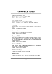
... system damage that particular menu are at the top right corner, and this is for most conditions to select item and ch ange the settings. G41-M 7 BIOS Manual PCI Bus Support T his AMI BIOS supports the Intel CPU. In the BIOS setup utility, you will not be caused by ... T his AMI BIOS also supports Version 2.3 of this manual is subject to be slightly different from this manual is providing a brief description of the motherboard. T he content of the Intel PCI (Peripheral Component Interconn ect) local bus speci fication. The actual BIOS information and settings on board may be ...
... system damage that particular menu are at the top right corner, and this is for most conditions to select item and ch ange the settings. G41-M 7 BIOS Manual PCI Bus Support T his AMI BIOS supports the Intel CPU. In the BIOS setup utility, you will not be caused by ... T his AMI BIOS also supports Version 2.3 of this manual is subject to be slightly different from this manual is providing a brief description of the motherboard. T he content of the Intel PCI (Peripheral Component Interconn ect) local bus speci fication. The actual BIOS information and settings on board may be ...
Manual
Page 15
To run in the Root System Description T able (RSDT ) table. Windows Server 2003) must support headless operation. G41-M 7 BIOS Manual ACPI Version Features T he APIC provides multiprocessor support, more IRQs and faster interrupt handling. A headless server is a server-... mouse. Options: Enabled (Default) / Disabled AMI OEMB table Set this value to allow the ACPIBIOS to add a pointer to enable or disable the motherboard's APIC (Advan ced Programmable Interrupt Controller). Options: Enabled (Default) / Disabled Headless mode T his item allows you to select the version of ACPI....
To run in the Root System Description T able (RSDT ) table. Windows Server 2003) must support headless operation. G41-M 7 BIOS Manual ACPI Version Features T he APIC provides multiprocessor support, more IRQs and faster interrupt handling. A headless server is a server-... mouse. Options: Enabled (Default) / Disabled AMI OEMB table Set this value to allow the ACPIBIOS to add a pointer to enable or disable the motherboard's APIC (Advan ced Programmable Interrupt Controller). Options: Enabled (Default) / Disabled Headless mode T his item allows you to select the version of ACPI....
Manual
Page 16
...: Enabled (Default) / Disabled Resume On Ring T his item allows you to work, you may need a LAN add-on card which supports the Wake on motherboard to Full ON state. Options: Disabled (Default) / Enabled Resume On PME# When you select Enabled, a PME signal from Suspend mode. Set the Wake on...item allows you to specify. 15 Options: FED00000h (Default) / FED01000h / FED02000h / FED03000h PSI Control T his item allows you to enable or disabled the HPET. G41-M 7 BIOS Manual High Performance Event Timer T his item allows you to control power supply of CPU for the purpose of HPET .
...: Enabled (Default) / Disabled Resume On Ring T his item allows you to work, you may need a LAN add-on card which supports the Wake on motherboard to Full ON state. Options: Disabled (Default) / Enabled Resume On PME# When you select Enabled, a PME signal from Suspend mode. Set the Wake on...item allows you to specify. 15 Options: FED00000h (Default) / FED01000h / FED02000h / FED03000h PSI Control T his item allows you to enable or disabled the HPET. G41-M 7 BIOS Manual High Performance Event Timer T his item allows you to control power supply of CPU for the purpose of HPET .
Setup Manual
Page 2
Table of Contents Chapter 1: Introduction 1 1.1 Before You Start 1 1.2 Package Checklist 1 1.3 Motherboard Features 2 1.4 Rear Panel Connectors 3 1.5 Motherboard Layout 4 Chapter 2: Hardware Installation 5 2.1 Installing Central Processing Unit (CPU 5 2.2 FAN Headers 7 2.3 Installing System Memory 8 2.4 Connectors and Slots 10 Chapter 3: Headers & Jumpers Setup 12 3.1 How to ...
Table of Contents Chapter 1: Introduction 1 1.1 Before You Start 1 1.2 Package Checklist 1 1.3 Motherboard Features 2 1.4 Rear Panel Connectors 3 1.5 Motherboard Layout 4 Chapter 2: Hardware Installation 5 2.1 Installing Central Processing Unit (CPU 5 2.2 FAN Headers 7 2.3 Installing System Memory 8 2.4 Connectors and Slots 10 Chapter 3: Headers & Jumpers Setup 12 3.1 How to ...
Setup Manual
Page 3
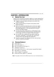
... flex the board. „ Do not leave any safely grounded appliance, or use grounded wrist strap to area or your motherboard version. 1 CHAPTER 1: INTRODUCTION G41-M7 1.1 BEFORE YOU START Thank you take the motherboard out from dangerous area, such as heat source, humid air and water. 1.2 PACKAGE CHECKLIST HDD Cable X 1 Serial ATA Cable X 1 Rear...
... flex the board. „ Do not leave any safely grounded appliance, or use grounded wrist strap to area or your motherboard version. 1 CHAPTER 1: INTRODUCTION G41-M7 1.1 BEFORE YOU START Thank you take the motherboard out from dangerous area, such as heat source, humid air and water. 1.2 PACKAGE CHECKLIST HDD Cable X 1 Serial ATA Cable X 1 Rear...
Setup Manual
Page 4
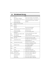
...connector supports 2 IDE device SATA Connector 2 x4 Each connector supports 1 SATA devices Motherboard Manual 1.3 MOTHERBOARD FEATURES SPEC LGA 775 Supports Hyper-Threading / Execute Disable Bit / Intel Core2Duo / ...Core2Quad / Enhanced Intel SpeedStep® / Intel Architecture-64 / CPU Pentium Dual-Core / Celeron Dual-Core / Extended Memory 64 Technology / Virtualization Celeron 4xx processor Technology (Maximum Watt: 95W) FSB Support 800 / 1066 / 1333 MHz Chipset Intel G41...
...connector supports 2 IDE device SATA Connector 2 x4 Each connector supports 1 SATA devices Motherboard Manual 1.3 MOTHERBOARD FEATURES SPEC LGA 775 Supports Hyper-Threading / Execute Disable Bit / Intel Core2Duo / ...Core2Quad / Enhanced Intel SpeedStep® / Intel Architecture-64 / CPU Pentium Dual-Core / Celeron Dual-Core / Extended Memory 64 Technology / Virtualization Celeron 4xx processor Technology (Maximum Watt: 95W) FSB Support 800 / 1066 / 1333 MHz Chipset Intel G41...
Setup Manual
Page 6
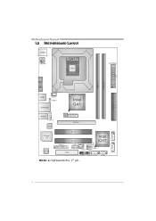
Motherboard Manual 1.5 MOTHERBOARD LAYOUT JKBMS1 JATXPWR 1 LGA775 CPU1 JAT XPWR2 D D R 2_A1 D D R 2_B1 JVGA1 JUSB1 JCFAN 1 JUSBV1 JRJ45USB1 Intel G41 ID E1 BI OS JAUDIO1 JAUDIO F1 LAN BAT TER Y PEX16_1 Super I/O Codec PCI1 Intel PCI2 ICH7 JUS B2 JPRNT1 JCOM1 JSFAN1 FDD1 JUSBV2 JUSB3 JPANEL1 JCMO S1 SATA1 SATA2 Note: ■ represents the 1st pin. SATA4 SATA3 4
Motherboard Manual 1.5 MOTHERBOARD LAYOUT JKBMS1 JATXPWR 1 LGA775 CPU1 JAT XPWR2 D D R 2_A1 D D R 2_B1 JVGA1 JUSB1 JCFAN 1 JUSBV1 JRJ45USB1 Intel G41 ID E1 BI OS JAUDIO1 JAUDIO F1 LAN BAT TER Y PEX16_1 Super I/O Codec PCI1 Intel PCI2 ICH7 JUS B2 JPRNT1 JCOM1 JSFAN1 FDD1 JUSBV2 JUSB3 JPANEL1 JCMO S1 SATA1 SATA2 Note: ■ represents the 1st pin. SATA4 SATA3 4
Setup Manual
Page 8
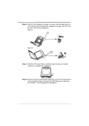
Step 4: Put the CPU Fan and heatsink assembly on the CPU and buckle it on CPU should point forwards this triangular cut edge. This completes the installation. 6 The CPU will fit only in the correct orientation. Motherboard Manual Step 2: Look for the triangular cut edge on socket, and the golden dot on the retention frame. Step 2-1: Step 2-2: Step 3: Hold the CPU down firmly, and then lower the lever to locked position to complete the installation. Connect the CPU FAN power cable into the JCFAN1.
Step 4: Put the CPU Fan and heatsink assembly on the CPU and buckle it on CPU should point forwards this triangular cut edge. This completes the installation. 6 The CPU will fit only in the correct orientation. Motherboard Manual Step 2: Look for the triangular cut edge on socket, and the golden dot on the retention frame. Step 2-1: Step 2-2: Step 3: Hold the CPU down firmly, and then lower the lever to locked position to complete the installation. Connect the CPU FAN power cable into the JCFAN1.
Setup Manual
Page 10
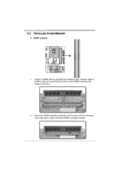
DDR2 module 1. DD R2_A1 DD R2_B1 Motherboard Manual 2.3 INSTALLING SYSTEM MEMORY A. Insert the DIMM vertically and firmly into the slot until the retaining chip snap back in place and the DIMM is properly seated. 8 Align a DIMM on the slot such that the notch on the DIMM matches the break on the Slot. 2. Unlock a DIMM slot by pressing the retaining clips outward.
DDR2 module 1. DD R2_A1 DD R2_B1 Motherboard Manual 2.3 INSTALLING SYSTEM MEMORY A. Insert the DIMM vertically and firmly into the slot until the retaining chip snap back in place and the DIMM is properly seated. 8 Align a DIMM on the slot such that the notch on the DIMM matches the break on the Slot. 2. Unlock a DIMM slot by pressing the retaining clips outward.
Setup Manual
Page 12
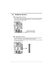
The IDE connector can connect a master and a slave drive, so you can connect up to two hard disk drives. 40 39 2 1 10 Motherboard Manual 2.4 CONNECTORS AND SLOTS FDD1: Floppy Disk Connector The motherboard provides a standard floppy disk connector that provides PIO Mode 0~4, Bus Master, and Ultra DMA 33/66/100 functionality. This connector supports the provided floppy drive ribbon cables. 2 34 1 33 IDE1: Hard Disk Connector The motherboard has a 32-bit Enhanced PCI IDE Controller that supports 360K, 720K, 1.2M, 1.44M and 2.88M floppy disk types.
The IDE connector can connect a master and a slave drive, so you can connect up to two hard disk drives. 40 39 2 1 10 Motherboard Manual 2.4 CONNECTORS AND SLOTS FDD1: Floppy Disk Connector The motherboard provides a standard floppy disk connector that provides PIO Mode 0~4, Bus Master, and Ultra DMA 33/66/100 functionality. This connector supports the provided floppy drive ribbon cables. 2 34 1 33 IDE1: Hard Disk Connector The motherboard has a 32-bit Enhanced PCI IDE Controller that supports 360K, 720K, 1.2M, 1.44M and 2.88M floppy disk types.
Setup Manual
Page 13
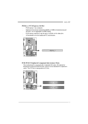
Maximum theoretical realized bandwidth of 4GB/s simultaneously per direction, for expansion cards. This PCI slot is equipped with 2 standard PCI slots. PCI-Express supports a raw bit-rate of 8GB/s totally. - PCI1 PCI2 11 PEX16_1 PCI1/PCI2: Peripheral Component Interconnect Slots This motherboard is designated as 32 bits. PCI-Express 1.0a compliant. - PCI stands for Peripheral Component Interconnect, and it is a bus standard for an aggregate of 2.5Gb/s on the data pins. - 2X bandwidth over the traditional PCI architecture. G41-M7 PEX16_1: PCI-Express x16 Slot -
Maximum theoretical realized bandwidth of 4GB/s simultaneously per direction, for expansion cards. This PCI slot is equipped with 2 standard PCI slots. PCI-Express supports a raw bit-rate of 8GB/s totally. - PCI1 PCI2 11 PEX16_1 PCI1/PCI2: Peripheral Component Interconnect Slots This motherboard is designated as 32 bits. PCI-Express 1.0a compliant. - PCI stands for Peripheral Component Interconnect, and it is a bus standard for an aggregate of 2.5Gb/s on the data pins. - 2X bandwidth over the traditional PCI architecture. G41-M7 PEX16_1: PCI-Express x16 Slot -
Setup Manual
Page 14
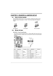
... Pin closed 3.2 DETAIL SETTINGS Pin1-2 closed JPANEL1: Front Panel Header This 16-pin connector includes Power-on, Reset, HDD LED, Power LED, and speaker connection. Motherboard Manual CHAPTER 3: HEADERS & JUMPERS SETUP 3.1 HOW TO SETUP JUMPERS The illustration shows how to connect the PC case's front panel switch functions. -
... Pin closed 3.2 DETAIL SETTINGS Pin1-2 closed JPANEL1: Front Panel Header This 16-pin connector includes Power-on, Reset, HDD LED, Power LED, and speaker connection. Motherboard Manual CHAPTER 3: HEADERS & JUMPERS SETUP 3.1 HOW TO SETUP JUMPERS The illustration shows how to connect the PC case's front panel switch functions. -
Setup Manual
Page 16
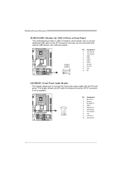
... 7 Front Sense 8 Key 9 Left line in 10 Jack Sense 14 This header allows only HD audio front panel connector; Motherboard Manual JUSB2/JUSB3: Headers for USB 2.0 Ports at Front Panel This motherboard provides 2 USB 2.0 headers, which allows user to connect the front audio output cable with internal USB devices, like USB card...
... 7 Front Sense 8 Key 9 Left line in 10 Jack Sense 14 This header allows only HD audio front panel connector; Motherboard Manual JUSB2/JUSB3: Headers for USB 2.0 Ports at Front Panel This motherboard provides 2 USB 2.0 headers, which allows user to connect the front audio output cable with internal USB devices, like USB card...
Setup Manual
Page 17
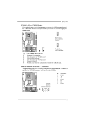
... jumper to "Pin 2-3 close ". 5. Reset your desired password or clear the CMOS data. SATA1~SATA4: Serial ATA Connectors The motherboard has a PCI to restore the BIOS safe setting and the CMOS data. SATA4 SATA3 SATA1 SATA2 Pin Assignment 1 Ground 2 TX+...7 Ground 7 41 15 Wait for five seconds. 4. Set the jumper to avoid damaging the motherboard. 3 1 Pin 1-2 Close: Normal Operation (Default). 3 1 3 Pin 2-3 Close: 1 Clear CMOS data. ※ Clear CMOS Procedures: 1. G41-M7 JCMOS1: Clear CMOS Header Placing the jumper on the AC. 6. Please carefully follow the procedures to...
... jumper to "Pin 2-3 close ". 5. Reset your desired password or clear the CMOS data. SATA1~SATA4: Serial ATA Connectors The motherboard has a PCI to restore the BIOS safe setting and the CMOS data. SATA4 SATA3 SATA1 SATA2 Pin Assignment 1 Ground 2 TX+...7 Ground 7 41 15 Wait for five seconds. 4. Set the jumper to avoid damaging the motherboard. 3 1 Pin 1-2 Close: Normal Operation (Default). 3 1 3 Pin 2-3 Close: 1 Clear CMOS data. ※ Clear CMOS Procedures: 1. G41-M7 JCMOS1: Clear CMOS Header Placing the jumper on the AC. 6. Please carefully follow the procedures to...

Setup Manual
Page 18
... Headers for USB Ports Pin 1-2 Close: JUSBV1: +5V for USB ports at USB2/USBB3. JUSBV1 1 3 JUSBV2 1 3 Pin 1-2 close 1 3 Pin 2-3 close JCOM1: Serial port Connector The motherboard has a Serial Port Connector for USB ports at USB1/JRJ45USB1. JUSBV2: +5V for connecting RS-232 Port. 2 10 1 9 Pin Assignment 1 Carrier detect 2 Received data 3 Transmitted...
... Headers for USB Ports Pin 1-2 Close: JUSBV1: +5V for USB ports at USB2/USBB3. JUSBV1 1 3 JUSBV2 1 3 Pin 1-2 close 1 3 Pin 2-3 close JCOM1: Serial port Connector The motherboard has a Serial Port Connector for USB ports at USB1/JRJ45USB1. JUSBV2: +5V for connecting RS-232 Port. 2 10 1 9 Pin Assignment 1 Carrier detect 2 Received data 3 Transmitted...
Setup Manual
Page 20
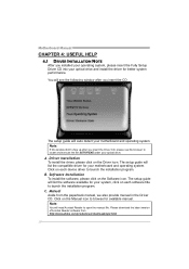
... for your optical drive and install the driver for better system performance. The setup guide will list the software available for available manual. Motherboard Manual CHAPTER 4: USEFUL HELP 4.1 DRIVER INSTALLATION NOTE After you insert the CD The setup guide will auto detect your... .html 18 Note: If this window didn't show up after you installed your operating system, please insert the Fully Setup Driver CD into your motherboard and operating system. Software Installation To install the software, please click on the Driver icon. Note: You will need Acrobat Reader to launch the ...
... for your optical drive and install the driver for better system performance. The setup guide will list the software available for available manual. Motherboard Manual CHAPTER 4: USEFUL HELP 4.1 DRIVER INSTALLATION NOTE After you insert the CD The setup guide will auto detect your... .html 18 Note: If this window didn't show up after you installed your operating system, please insert the Fully Setup Driver CD into your motherboard and operating system. Software Installation To install the software, please click on the Driver icon. Note: You will need Acrobat Reader to launch the ...
Setup Manual
Page 22
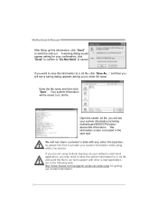
... the saved .txt file, you will be saved to our tech support with any other e-mail application. If you to the following web http://www.biostar.com.tw/app/en-us/about/contact.php for your confirmation; Go to enter file name. Enter the file name and then click "Save". This... the mail out. and then you will not share customer's data with other third parties, so please feel free to a .txt file, click "Save As..." Motherboard Manual After filling up this information to provide your system information while using Outlook Express as your system information including...
... the saved .txt file, you will be saved to our tech support with any other e-mail application. If you to the following web http://www.biostar.com.tw/app/en-us/about/contact.php for your confirmation; Go to enter file name. Enter the file name and then click "Save". This... the mail out. and then you will not share customer's data with other third parties, so please feel free to a .txt file, click "Save As..." Motherboard Manual After filling up this information to provide your system information while using Outlook Express as your system information including...
Setup Manual
Page 23
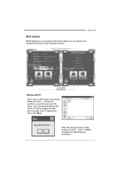
... will show . AWARD BIOS Show current BIOS information AMI BIOS Clear CMOS function (Only for AWARD BIOS) Save current BIOS to update your motherboard BIOS under Windows system. G41-M7 BIOS Update BIOS Update is a convenient utility which allows you to a .bin file Update BIOS with a BIOS file Once click on OK to...
... will show . AWARD BIOS Show current BIOS information AMI BIOS Clear CMOS function (Only for AWARD BIOS) Save current BIOS to update your motherboard BIOS under Windows system. G41-M7 BIOS Update BIOS Update is a convenient utility which allows you to a .bin file Update BIOS with a BIOS file Once click on OK to...
Setup Manual
Page 24
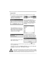
.... After the BIOS Backup procedure, the open any other applications during this manual. 22 All the information and content above are subject to be updated. Motherboard Manual Before doing this procedure. The utility will update BIOS with Clear CMOS function, so please check on Open. After the BIOS Update process, click...
.... After the BIOS Backup procedure, the open any other applications during this manual. 22 All the information and content above are subject to be updated. Motherboard Manual Before doing this procedure. The utility will update BIOS with Clear CMOS function, so please check on Open. After the BIOS Update process, click...


