Setup Manual
Page 2
... 1: Introduction 1 1.1 Before You Start 1 1.2 Package Checklist 1 1.3 Motherboard Features 2 1.4 Rear Panel Connectors 3 1.5 Motherboard Layout 4 Chapter 2: Hardware Installation 5 2.1 Installing Central Processing Unit (CPU 5 2.2 FAN Headers 6 2.3 Installing System Memory 7 2.4 Connectors and Slots 9 Chapter 3: Headers & Jumpers Setup 12 3.1 How to Setup Jumpers 12 3.2 Detail Settings 12 Chapter 4: Useful Help 16 4.1 Driver Installation Note 16 4.2 Software...
... 1: Introduction 1 1.1 Before You Start 1 1.2 Package Checklist 1 1.3 Motherboard Features 2 1.4 Rear Panel Connectors 3 1.5 Motherboard Layout 4 Chapter 2: Hardware Installation 5 2.1 Installing Central Processing Unit (CPU 5 2.2 FAN Headers 6 2.3 Installing System Memory 7 2.4 Connectors and Slots 9 Chapter 3: Headers & Jumpers Setup 12 3.1 How to Setup Jumpers 12 3.2 Detail Settings 12 Chapter 4: Useful Help 16 4.1 Driver Installation Note 16 4.2 Software...
Setup Manual
Page 4
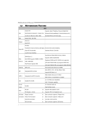
...533 MHz only supports DDR2 533) (CPU with FSB 800 MHz only supports DDR2 667/800) Graphics GMA 3100 Max Shared Video Memory is 256MB IDE Integrated IDE Controller Ultra DMA 33 / 66 / 100 Bus Master Mode supports PIO Mode 0~4 SATA 2 Integrated ... CPU Intel Pentium4 /Celeron D / Celeron 3xx Enhanced Intel SpeedStep® / Intel Architecture-64 / processors (Maximum Watt: 95W) Extended Memory 64 Technology FSB Support 800 / 533 MHz Chipset Intel G31 Intel ICH7 ITE 8721 Super I/O Provides the most commonly used legacy Environment Control initiatives, Super I/O functionality.
...533 MHz only supports DDR2 533) (CPU with FSB 800 MHz only supports DDR2 667/800) Graphics GMA 3100 Max Shared Video Memory is 256MB IDE Integrated IDE Controller Ultra DMA 33 / 66 / 100 Bus Master Mode supports PIO Mode 0~4 SATA 2 Integrated ... CPU Intel Pentium4 /Celeron D / Celeron 3xx Enhanced Intel SpeedStep® / Intel Architecture-64 / processors (Maximum Watt: 95W) Extended Memory 64 Technology FSB Support 800 / 533 MHz Chipset Intel G31 Intel ICH7 ITE 8721 Super I/O Provides the most commonly used legacy Environment Control initiatives, Super I/O functionality.

Setup Manual
Page 9
2.3 INSTALLING SYSTEM MEMORY A. Insert the DIMM vertically and firmly into the slot until the retaining chip snap back in place and the DIMM is properly seated. 7 DDR2 module G31-M4 DDR 2 _A1 DDR 2 _B1 1. Align a DIMM on the slot such that the notch on the DIMM matches the break on the Slot. 2. Unlock a DIMM slot by pressing the retaining clips outward.
2.3 INSTALLING SYSTEM MEMORY A. Insert the DIMM vertically and firmly into the slot until the retaining chip snap back in place and the DIMM is properly seated. 7 DDR2 module G31-M4 DDR 2 _A1 DDR 2 _B1 1. Align a DIMM on the slot such that the notch on the DIMM matches the break on the Slot. 2. Unlock a DIMM slot by pressing the retaining clips outward.
Setup Manual
Page 10
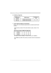
Motherboard Manual B. Dual Channel Status DDR2_A1 DDR2_B1 Disabled O X Disabled X O Enabled O O (O means memory installed, X means memory not installed.) The DRAM bus width of the same density in pairs, shown in the table. Memory Capacity DIMM Socket Location DDR2_A1 DDR2_B1 DDR2 Module 256MB/512MB/1GB/2GB 256MB/512MB/1GB/2GB Total Memory Size Max is 4GB. C. Dual Channel Memory Installation Please refer to the following requirements to activate Dual Channel function: Install memory module of the memory module must be the same(x8 or x16) 8
Motherboard Manual B. Dual Channel Status DDR2_A1 DDR2_B1 Disabled O X Disabled X O Enabled O O (O means memory installed, X means memory not installed.) The DRAM bus width of the same density in pairs, shown in the table. Memory Capacity DIMM Socket Location DDR2_A1 DDR2_B1 DDR2 Module 256MB/512MB/1GB/2GB 256MB/512MB/1GB/2GB Total Memory Size Max is 4GB. C. Dual Channel Memory Installation Please refer to the following requirements to activate Dual Channel function: Install memory module of the memory module must be the same(x8 or x16) 8
Setup Manual
Page 25
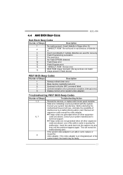
... the problem happens again. Insert the cards back into the system one of interference by a malfunctioning add-in card. 4.4 AMI BIOS BEEP CODE G31-M4 Boot Block Beep Codes Number of Beeps Description 1 No media present. (Insert diskette in floppy drive A:) 2 "AMIBOOT.ROM" file not found ... (file layout does not match image present in flash device) POST BIOS Beep Codes Number of Beeps Description 1 Memory refresh timer error 3 Base memory read/write test error 6 Keyboard controller BAT command failed 7 General exception error (processor exception interrupt error) 8 Display...
... the problem happens again. Insert the cards back into the system one of interference by a malfunctioning add-in card. 4.4 AMI BIOS BEEP CODE G31-M4 Boot Block Beep Codes Number of Beeps Description 1 No media present. (Insert diskette in floppy drive A:) 2 "AMIBOOT.ROM" file not found ... (file layout does not match image present in flash device) POST BIOS Beep Codes Number of Beeps Description 1 Memory refresh timer error 3 Base memory read/write test error 6 Keyboard controller BAT command failed 7 General exception error (processor exception interrupt error) 8 Display...
Setup Manual
Page 44
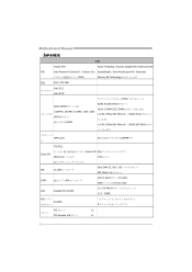
... 478 Hyper-Threading / Execute Disable Bit / Enhanced Intel CPU Intel Pentium4 /Celeron D / Celeron 3xx SpeedStep® / Intel Architecture-64 / Extended 95W) Memory 64 Technology FSB 800 / 533 MHz Intel G31 Intel ICH7 DDR2 DDR2 DIMM x 2 各DIMMは 256MB / 512MB / 1GB / 2GB DDR2 4GB DDR2 533/667/800 DIMMとECC DIMM...
... 478 Hyper-Threading / Execute Disable Bit / Enhanced Intel CPU Intel Pentium4 /Celeron D / Celeron 3xx SpeedStep® / Intel Architecture-64 / Extended 95W) Memory 64 Technology FSB 800 / 533 MHz Intel G31 Intel ICH7 DDR2 DDR2 DIMM x 2 各DIMMは 256MB / 512MB / 1GB / 2GB DDR2 4GB DDR2 533/667/800 DIMMとECC DIMM...
Bios Setup
Page 4
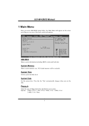
... Help F10 Save and Exit ESC Exit vxx.xx (C)Copyright 1985-200x, American Megatrends, Inc. G31-M4 BIOS Manual 1 Main Menu Once you set the date. System Memory Shows system memory size, VGA shard memory will appear on the screen providing an overview of floppy disk drive installed in / None 3... Main Advanced BIOS SETUP UTILITY PCIPnP Boot Chipset Performance Exit System Overview AMI BIOS Version :01.01.01 Build Date:01/01/10 System Memory Size : Use [ENTER], [TAB] or [SHIFT-TAB] to configure system Time. System Time System Date Floppy A > IDE/SATA Configuration [00:00...
... Help F10 Save and Exit ESC Exit vxx.xx (C)Copyright 1985-200x, American Megatrends, Inc. G31-M4 BIOS Manual 1 Main Menu Once you set the date. System Memory Shows system memory size, VGA shard memory will appear on the screen providing an overview of floppy disk drive installed in / None 3... Main Advanced BIOS SETUP UTILITY PCIPnP Boot Chipset Performance Exit System Overview AMI BIOS Version :01.01.01 Build Date:01/01/10 System Memory Size : Use [ENTER], [TAB] or [SHIFT-TAB] to configure system Time. System Time System Date Floppy A > IDE/SATA Configuration [00:00...
Bios Setup
Page 9
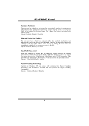
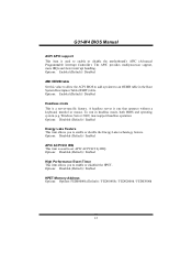
... for other OS (OS not optimized for a 64-byte cache line. Options: Enabled (Default) / Disabled 8 Before it as well. G31-M4 BIOS Manual Hardware Prefetcher The processor has a hardware prefetcher that automatically analyzes its capabilities. Options: Enabled (Default) / Disabled Adjacent Cache Line ... the operating system executes the CPUID instruction to identify the processor and its requirements and prefetches data and instructions from the memory into the Level 2 cache that automatically fetches an extra 64-byte cache line whenever the processor requests for Hyper Threading...
... for other OS (OS not optimized for a 64-byte cache line. Options: Enabled (Default) / Disabled 8 Before it as well. G31-M4 BIOS Manual Hardware Prefetcher The processor has a hardware prefetcher that automatically analyzes its capabilities. Options: Enabled (Default) / Disabled Adjacent Cache Line ... the operating system executes the CPUID instruction to identify the processor and its requirements and prefetches data and instructions from the memory into the Level 2 cache that automatically fetches an extra 64-byte cache line whenever the processor requests for Hyper Threading...
Bios Setup
Page 13
...to allow the ACPI BIOS to add a pointer to enable or disable the Energy Lake technology feature. Options: Disabled (Default) / Enabled HPET Memory Address Options: Options: FED00000h (Default) / FED01000h / FED02000h / FED03000h 12 Options: Disabled (Default) / Enabled Energy Lake Feature This item .../ Disabled Headless mode This is one that operates without a keyboard, monitor or mouse. Windows Server 2003) must support headless operation. G31-M4 BIOS Manual ACPI APIC support This item is used to enable or disabled the HPET. The APIC provides multiprocessor support, more IRQs and ...
...to allow the ACPI BIOS to add a pointer to enable or disable the Energy Lake technology feature. Options: Disabled (Default) / Enabled HPET Memory Address Options: Options: FED00000h (Default) / FED01000h / FED02000h / FED03000h 12 Options: Disabled (Default) / Enabled Energy Lake Feature This item .../ Disabled Headless mode This is one that operates without a keyboard, monitor or mouse. Windows Server 2003) must support headless operation. G31-M4 BIOS Manual ACPI APIC support This item is used to enable or disabled the HPET. The APIC provides multiprocessor support, more IRQs and ...
Bios Setup
Page 18
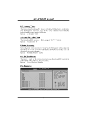
...) / Enabled PCI IDE BusMaster This item is available to another PCI device. Change Option F1 General Help F10 Save and Exit ESC Exit Reserved Memory Size [Disabled] vxx.xx (C)Copyright 1985-200x, American Megatrends, Inc. 17 Options: Enabled (Default) / Disabled PCI Resource BIOS SETUP UTILITY PCIPnP...the longer the PCI device can hold the PCI bus before handing it to their display as a way to perform DMA (Direct Memory Access) transfers. G31-M4 BIOS Manual PCI Latency Timer This item controls how long a PCI device can retain control of the bus before another takes over...
...) / Enabled PCI IDE BusMaster This item is available to another PCI device. Change Option F1 General Help F10 Save and Exit ESC Exit Reserved Memory Size [Disabled] vxx.xx (C)Copyright 1985-200x, American Megatrends, Inc. 17 Options: Enabled (Default) / Disabled PCI Resource BIOS SETUP UTILITY PCIPnP...the longer the PCI device can hold the PCI bus before handing it to their display as a way to perform DMA (Direct Memory Access) transfers. G31-M4 BIOS Manual PCI Latency Timer This item controls how long a PCI device can retain control of the bus before another takes over...
Bios Setup
Page 19
... states. Select Screen Select Item +- Options: Disabled (Default) / Enabled 18 Options: Available (Default) / Reserved Reserved Memory Size This item allows BIOS to reserve certain memory size for OS which does not support ASPM. Change Option F1 General Help F10 Save and Exit ESC Exit vxx.xx...configuration for the PCI Express devices before the operating system boots. The option "Available" means the channel is going to assign automatically. G31-M4 BIOS Manual IRQ3/4/5/7/9/10/11/14/15 These items will allow you to assign each system interrupt a type, depending on the type of...
... states. Select Screen Select Item +- Options: Disabled (Default) / Enabled 18 Options: Available (Default) / Reserved Reserved Memory Size This item allows BIOS to reserve certain memory size for OS which does not support ASPM. Change Option F1 General Help F10 Save and Exit ESC Exit vxx.xx...configuration for the PCI Express devices before the operating system boots. The option "Available" means the channel is going to assign automatically. G31-M4 BIOS Manual IRQ3/4/5/7/9/10/11/14/15 These items will allow you to assign each system interrupt a type, depending on the type of...
Bios Setup
Page 24
...PCI] Internal Graphics Mode Select [Enabled, 8MB] PEG Port Configuration PEG Port [Auto] > Video Function Configuration ENABLE: Allow remapping of memory. Select Screen Select Item +- It also coordinates communications with the PCI bus. This chipset manage bus speeds and access to Sub Screen F1...ESC Exit vxx.xx (C)Copyright 1985-200x, American Megatrends, Inc. DISABLE: Do not allow remapping of overlapped PCI memory above the total physical memory. G31-M4 BIOS Manual 5 Chipset Menu This submenu allows you to configure the specific features of the chipset installed on your ...
...PCI] Internal Graphics Mode Select [Enabled, 8MB] PEG Port Configuration PEG Port [Auto] > Video Function Configuration ENABLE: Allow remapping of memory. Select Screen Select Item +- It also coordinates communications with the PCI bus. This chipset manage bus speeds and access to Sub Screen F1...ESC Exit vxx.xx (C)Copyright 1985-200x, American Megatrends, Inc. DISABLE: Do not allow remapping of overlapped PCI memory above the total physical memory. G31-M4 BIOS Manual 5 Chipset Menu This submenu allows you to configure the specific features of the chipset installed on your ...
Bios Setup
Page 25
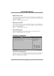
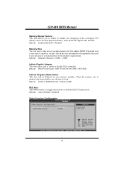
When this area is decided, this area of system memory for the memory requirements. Check the user information of the overlapped PCI memory above the total physical memory. G31-M4 BIOS Manual Memory Remap Feature This item allows you to enable or disable VGA controller. Options: Enabled, 8MB (... be fixed. Options: Auto (Default) / Disabled Video Function Configuration BIOS SETUP UTILITY Chipset Video Function Configuration DVMT Mode Select DVMT/FIXED Memory [DVMT Mode] [256MB] Options Fixed Mode DVMT Mode Select Screen Select Item +- Options: PEG/PCI (Default) / IGD / PCI...
When this area is decided, this area of system memory for the memory requirements. Check the user information of the overlapped PCI memory above the total physical memory. G31-M4 BIOS Manual Memory Remap Feature This item allows you to enable or disable VGA controller. Options: Enabled, 8MB (... be fixed. Options: Auto (Default) / Disabled Video Function Configuration BIOS SETUP UTILITY Chipset Video Function Configuration DVMT Mode Select DVMT/FIXED Memory [DVMT Mode] [256MB] Options Fixed Mode DVMT Mode Select Screen Select Item +- Options: PEG/PCI (Default) / IGD / PCI...
Bios Setup
Page 26
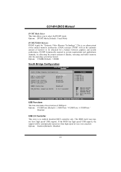
... Disabled 25 This is to enabled/ disabled EHCI controller only. DVMT dynamically respond to be automatically turned on when high speed devices were attached. G31-M4 BIOS Manual DVMT Mode Select This item allows you to 2 seconds] Options Disabled 2 USB Ports 4 USB Ports 6 USB Ports 8 USB ...Ports Select Screen Select Item +- USB Functions The item determines the activation of memory to system requirements and applications demands, by allocating the proper amount of the unified memory architecture (UMA) concept. If the BIOS has high speed USB support, the support will set ...
... Disabled 25 This is to enabled/ disabled EHCI controller only. DVMT dynamically respond to be automatically turned on when high speed devices were attached. G31-M4 BIOS Manual DVMT Mode Select This item allows you to 2 seconds] Options Disabled 2 USB Ports 4 USB Ports 6 USB Ports 8 USB ...Ports Select Screen Select Item +- USB Functions The item determines the activation of memory to system requirements and applications demands, by allocating the proper amount of the unified memory architecture (UMA) concept. If the BIOS has high speed USB support, the support will set ...

Bios Setup
Page 28
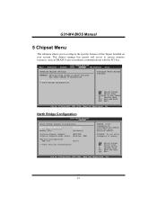
... +40mV +80mV +120mV DRAM Frequency [Auto] Configure DRAM Timing by SPD [Enabled] Select Screen Select Item EnterGo to select Memory Voltage Control. DRAM Frequency This item allows you use the default setting. G31-M4 BIOS Manual 6 Performance Menu This submenu allows you to change voltage and clock of this menu may cause system...
... +40mV +80mV +120mV DRAM Frequency [Auto] Configure DRAM Timing by SPD [Enabled] Select Screen Select Item EnterGo to select Memory Voltage Control. DRAM Frequency This item allows you use the default setting. G31-M4 BIOS Manual 6 Performance Menu This submenu allows you to change voltage and clock of this menu may cause system...


