Setup Manual
Page 2
Table of Contents Chapter 1: Introduction 1 1.1 Before You Start 1 1.2 Package Checklist 1 1.3 Motherboard Features 2 1.4 Rear Panel Connectors 3 1.5 Motherboard Layout 4 Chapter 2: Hardware Installation 5 2.1 Installing Central Processing Unit (CPU 5 2.2 FAN Headers 6 2.3 Installing System Memory 7 2.4 Connectors and Slots 9 Chapter 3: Headers & Jumpers Setup 12 3.1 How to Setup Jumpers 12 3.2 Detail Settings 12 Chapter 4: Useful Help 16 4.1 ...
Table of Contents Chapter 1: Introduction 1 1.1 Before You Start 1 1.2 Package Checklist 1 1.3 Motherboard Features 2 1.4 Rear Panel Connectors 3 1.5 Motherboard Layout 4 Chapter 2: Hardware Installation 5 2.1 Installing Central Processing Unit (CPU 5 2.2 FAN Headers 6 2.3 Installing System Memory 7 2.4 Connectors and Slots 9 Chapter 3: Headers & Jumpers Setup 12 3.1 How to Setup Jumpers 12 3.2 Detail Settings 12 Chapter 4: Useful Help 16 4.1 ...
Setup Manual
Page 4
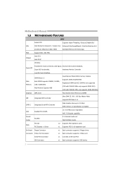
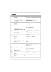
... Port Connector x1 Connects to 3.0 Gb/s. Motherboard Manual 1.3 MOTHERBOARD FEATURES SPEC Socket 478 Supports Hyper-Threading / Execute Disable Bit / CPU Intel Pentium4 /Celeron D / Celeron 3xx Enhanced Intel SpeedStep® / Intel Architecture-64 / processors (Maximum Watt: 95W) Extended... Memory 64 Technology FSB Support 800 / 533 MHz Chipset Intel G31 Intel ICH7 ITE 8721 Super I/O Provides the most commonly used legacy Environment Control initiatives, Super I/O functionality. Hardware Monitor Controller ...
... Port Connector x1 Connects to 3.0 Gb/s. Motherboard Manual 1.3 MOTHERBOARD FEATURES SPEC Socket 478 Supports Hyper-Threading / Execute Disable Bit / CPU Intel Pentium4 /Celeron D / Celeron 3xx Enhanced Intel SpeedStep® / Intel Architecture-64 / processors (Maximum Watt: 95W) Extended... Memory 64 Technology FSB Support 800 / 533 MHz Chipset Intel G31 Intel ICH7 ITE 8721 Super I/O Provides the most commonly used legacy Environment Control initiatives, Super I/O functionality. Hardware Monitor Controller ...
Setup Manual
Page 5
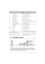
...Port Audio Jack Board Size 200 (W) x 235 (L) mm OS Support Windows 2000 / XP / Vista / 7 G31-M4 SPEC x4 Each connector supports 1 SATA devices x1 Supports front panel facilities x1 Supports front panel audio function x1 CPU Fan power supply x1 System Fan Power supply x1 Restore CMOS data to factory default x2... x1 Connect to D-SUB monitor x1 Connect to RJ-45 ethernet cable x4 Connect to USB devices x3 Provide Audio-In/Out and microphone connection Biostar reserves the right to the audio port, please use the Line In (blue) and Mic In (Pink) audio jack. 3 However, when connecting external ...
...Port Audio Jack Board Size 200 (W) x 235 (L) mm OS Support Windows 2000 / XP / Vista / 7 G31-M4 SPEC x4 Each connector supports 1 SATA devices x1 Supports front panel facilities x1 Supports front panel audio function x1 CPU Fan power supply x1 System Fan Power supply x1 Restore CMOS data to factory default x2... x1 Connect to D-SUB monitor x1 Connect to RJ-45 ethernet cable x4 Connect to USB devices x3 Provide Audio-In/Out and microphone connection Biostar reserves the right to the audio port, please use the Line In (blue) and Mic In (Pink) audio jack. 3 However, when connecting external ...

Setup Manual
Page 7
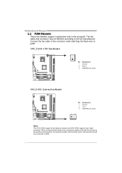
Step 3: Hold the CPU down firmly, and then close the lever to a 90-degree angle. This completes the installation. 5 Step 2: Look for the white dot/cut edge should point wards the lever pivot. G31-M4 CHAPTER 2: HARDWARE INSTALLATION 2.1 INSTALLING CENTRAL PROCESSING UNIT (CPU) Step 1: Pull the lever sideways away from the socket and then raise the lever up to complete the installation. Step 4: Put the CPU Fan on the CPU and buckle it. The white dot/cut edge. Connect the CPU FAN power cable to the CPU_FAN1. The CPU will fit only in the correct orientation.
Step 3: Hold the CPU down firmly, and then close the lever to a 90-degree angle. This completes the installation. 5 Step 2: Look for the white dot/cut edge should point wards the lever pivot. G31-M4 CHAPTER 2: HARDWARE INSTALLATION 2.1 INSTALLING CENTRAL PROCESSING UNIT (CPU) Step 1: Pull the lever sideways away from the socket and then raise the lever up to complete the installation. Step 4: Put the CPU Fan on the CPU and buckle it. The white dot/cut edge. Connect the CPU FAN power cable to the CPU_FAN1. The CPU will fit only in the correct orientation.
Setup Manual
Page 8
... is the positive and should be connected to pin#2, and the black wire is Ground and should be different according to the fan manufacturer. CPU_FAN1: CPU Fan Header 3 1 Pin Assignment 1 Ground 2 Power 3 FAN RPM rate sense SYS_FAN1: System Fan Header Pin Assignment 1 Ground 2 +12V 3 FAN RPM rate sense 13 Note: The...
... is the positive and should be connected to pin#2, and the black wire is Ground and should be different according to the fan manufacturer. CPU_FAN1: CPU Fan Header 3 1 Pin Assignment 1 Ground 2 Power 3 FAN RPM rate sense SYS_FAN1: System Fan Header Pin Assignment 1 Ground 2 +12V 3 FAN RPM rate sense 13 Note: The...
Setup Manual
Page 12
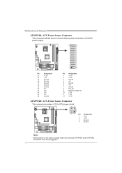
... 3 Ground 4 +5V 5 Ground 6 +5V 7 Ground 8 PW_OK 9 Standby Voltage+5V 10 +12V 11 +12V 12 +3.3V ATXPWR2: ATX Power Source Connector This connector provides +12V to CPU power circuit. 32 4 1 Pin Assignment 1 +12V 2 +12V 3 Ground 4 Ground Note: Before power on the system, please make sure that both ATXPWR1 and ATXPWR2 connectors have...
... 3 Ground 4 +5V 5 Ground 6 +5V 7 Ground 8 PW_OK 9 Standby Voltage+5V 10 +12V 11 +12V 12 +3.3V ATXPWR2: ATX Power Source Connector This connector provides +12V to CPU power circuit. 32 4 1 Pin Assignment 1 +12V 2 +12V 3 Ground 4 Ground Note: Before power on the system, please make sure that both ATXPWR1 and ATXPWR2 connectors have...
Setup Manual
Page 20
...saved .txt file, you may need to save this information, click "Send" to send the mail out. Go to the following web http://www.biostar.com.tw/app/en-us/about/contact.php for your default e-mail client application, you will not share customer's data with other third parties, ...so please feel free to provide your system information including motherboard/BIOS/CPU/video/ device/OS information. Enter the file name and then click "Save". If you want to save the system information to a .txt file ...
...saved .txt file, you may need to save this information, click "Send" to send the mail out. Go to the following web http://www.biostar.com.tw/app/en-us/about/contact.php for your default e-mail client application, you will not share customer's data with other third parties, ...so please feel free to provide your system information including motherboard/BIOS/CPU/video/ device/OS information. Enter the file name and then click "Save". If you want to save the system information to a .txt file ...
Setup Manual
Page 23
... avoid a damage of the CPU, and the system may not power on again. Remove the power cord from power supply for seconds. 3. In this case, please double check: 1. Power on the system again. 21 G31-M4 4.3 EXTRA INFORMATION CPU Overheated If the system shutdown ...automatically after power on system for seconds. 3. Or you can: 1. The CPU cooler surface is fulfilling with the CPU surface. 2. Wait for seconds, that means the...
... avoid a damage of the CPU, and the system may not power on again. Remove the power cord from power supply for seconds. 3. In this case, please double check: 1. Power on the system again. 21 G31-M4 4.3 EXTRA INFORMATION CPU Overheated If the system shutdown ...automatically after power on system for seconds. 3. Or you can: 1. The CPU cooler surface is fulfilling with the CPU surface. 2. Wait for seconds, that means the...
Setup Manual
Page 44
...仕様 Socket 478 Hyper-Threading / Execute Disable Bit / Enhanced Intel CPU Intel Pentium4 /Celeron D / Celeron 3xx SpeedStep® / Intel Architecture-64 / Extended 95W) Memory 64 Technology FSB 800 / 533 MHz Intel G31 Intel ICH7 DDR2 DDR2 DIMM x 2 各DIMMは 256MB / 512MB... / 1GB / 2GB DDR2 4GB DDR2 533/667/800 DIMMとECC DIMM CPUのFSBを533 MHzの唯一のDDR2 533...
...仕様 Socket 478 Hyper-Threading / Execute Disable Bit / Enhanced Intel CPU Intel Pentium4 /Celeron D / Celeron 3xx SpeedStep® / Intel Architecture-64 / Extended 95W) Memory 64 Technology FSB 800 / 533 MHz Intel G31 Intel ICH7 DDR2 DDR2 DIMM x 2 各DIMMは 256MB / 512MB... / 1GB / 2GB DDR2 4GB DDR2 533/667/800 DIMMとECC DIMM CPUのFSBを533 MHzの唯一のDDR2 533...
Bios Setup
Page 3
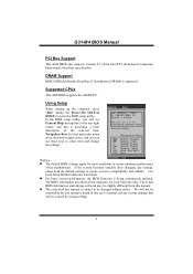
Supported CPUs This AMI BIOS supports the AMD CPU. In the BIOS setup utility, you can use these keys to select item and change the settings. The actual BIOS information and settings on board ..., the BIOS firmware is supported. We will see General Help description at the bottom right corner, and you will not be caused by wrong-settings. 2 G31-M4 BIOS Manual PCI Bus Support This AMI BIOS also supports Version 2.3 of this manual is for your reference only. Navigation Keys for that may be...
Supported CPUs This AMI BIOS supports the AMD CPU. In the BIOS setup utility, you can use these keys to select item and change the settings. The actual BIOS information and settings on board ..., the BIOS firmware is supported. We will see General Help description at the bottom right corner, and you will not be caused by wrong-settings. 2 G31-M4 BIOS Manual PCI Bus Support This AMI BIOS also supports Version 2.3 of this manual is for your reference only. Navigation Keys for that may be...
Bios Setup
Page 8
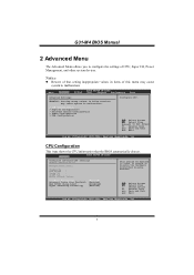
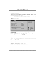
G31-M4 BIOS Manual 2 Advanced Menu The Advanced Menu allows you to configure the settings of this menu may cause system to malfunction. > CPU Configuration > SuperIO Configuration > Hardware Health Configuration > Power Configuration > USB Configuration Configure CPU. Change Option F1 General Help F10 Save and Exit ...WARNING: Setting wrong values in order to enable or disable the Hardware Prefetcher Disable Feature. Advanced BIOS SETUP UTILITY Configure advanced CPU settings Module Version:3F.07 Manufacturer:Intel Frequency : FSB Speed : Cache L1 : Cache L2 : Ratio Actual Value: This...
G31-M4 BIOS Manual 2 Advanced Menu The Advanced Menu allows you to configure the settings of this menu may cause system to malfunction. > CPU Configuration > SuperIO Configuration > Hardware Health Configuration > Power Configuration > USB Configuration Configure CPU. Change Option F1 General Help F10 Save and Exit ...WARNING: Setting wrong values in order to enable or disable the Hardware Prefetcher Disable Feature. Advanced BIOS SETUP UTILITY Configure advanced CPU settings Module Version:3F.07 Manufacturer:Intel Frequency : FSB Speed : Cache L1 : Cache L2 : Ratio Actual Value: This...
Bios Setup
Page 11
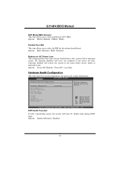
G31-M4 BIOS Manual ECP Mode DMA Channel This item allows you to select the IRQ for the onboard parallel port. Options: IRQ7 (Default) / IRQ5 / Disabled Restore on AC Power Loss This setting specifies how your system should behave after a power fail or interrupts occurs. CPU Temperature System Temperature CPU... FAN Speed SYS1 FAN Speed +12.0V +5.00V CPU Vcore Chipset Voltage DDR Voltage Select Screen Select Item +- H/W Health Function If with a ...
G31-M4 BIOS Manual ECP Mode DMA Channel This item allows you to select the IRQ for the onboard parallel port. Options: IRQ7 (Default) / IRQ5 / Disabled Restore on AC Power Loss This setting specifies how your system should behave after a power fail or interrupts occurs. CPU Temperature System Temperature CPU... FAN Speed SYS1 FAN Speed +12.0V +5.00V CPU Vcore Chipset Voltage DDR Voltage Select Screen Select Item +- H/W Health Function If with a ...
Bios Setup
Page 12
...) (Default) Suspend to RAM Auto POS+STR Repost Video on S3 Resume The item allows you to determine whether to select the version of ACPI. G31-M4 BIOS Manual Shutdown Temperature This item allows you to select the suspend type under Windows 98 ACPI mode. Suspend mode The item allows you to...
...) (Default) Suspend to RAM Auto POS+STR Repost Video on S3 Resume The item allows you to determine whether to select the version of ACPI. G31-M4 BIOS Manual Shutdown Temperature This item allows you to select the suspend type under Windows 98 ACPI mode. Suspend mode The item allows you to...

Bios Setup
Page 17
... Chipset Performance Exit Advanced PCI/PnP Settings WARNING: Setting wrong values in items of the CPU itself uses when communicating with its own special components. The rest of the cards will be initialized by selecting "Yes". G31-M4 BIOS Manual 3 PCIPnP Menu This section describes configuring the PCI bus system. Options: No (Default...
... Chipset Performance Exit Advanced PCI/PnP Settings WARNING: Setting wrong values in items of the CPU itself uses when communicating with its own special components. The rest of the cards will be initialized by selecting "Yes". G31-M4 BIOS Manual 3 PCIPnP Menu This section describes configuring the PCI bus system. Options: No (Default...

Bios Setup
Page 28
... allows you to Sub Screen F1 General Help F10 Save and Exit ESC Exit vxx.xx (C)Copyright 1985-200x, American Megatrends, Inc. G31-M4 BIOS Manual 6 Performance Menu This submenu allows you to change voltage and clock of this menu may damage the device.) Notice z Beware... of that setting inappropriate values in items of various devices. (However, we suggest you use the default setting. CPU Voltage Chipset Voltage DDR Voltage [Default ] [Default ] [Default ] Options Default +40mV +80mV +120mV DRAM Frequency [Auto] Configure DRAM Timing by SPD...
... allows you to Sub Screen F1 General Help F10 Save and Exit ESC Exit vxx.xx (C)Copyright 1985-200x, American Megatrends, Inc. G31-M4 BIOS Manual 6 Performance Menu This submenu allows you to change voltage and clock of this menu may damage the device.) Notice z Beware... of that setting inappropriate values in items of various devices. (However, we suggest you use the default setting. CPU Voltage Chipset Voltage DDR Voltage [Default ] [Default ] [Default ] Options Default +40mV +80mV +120mV DRAM Frequency [Auto] Configure DRAM Timing by SPD...


