Update Manual
Page 1
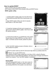
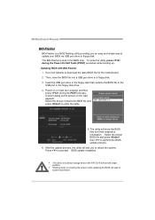
... load Optimized Defaults, and select Save Changes and Reset to update BIOS? Backup BIOS Click the Backup BIOS button on OK to request your BIOS file in the system, and click Save. tw . 3. Please select the proper BIOS file, and then click on the main screen. 4. While the system boots up and the full screen logo shows up to reboot the system. 7. Download the proper BIOS from the DVD Driver. 2. Open BIOS Update Utility...
... load Optimized Defaults, and select Save Changes and Reset to update BIOS? Backup BIOS Click the Backup BIOS button on OK to request your BIOS file in the system, and click Save. tw . 3. Please select the proper BIOS file, and then click on the main screen. 4. While the system boots up and the full screen logo shows up to reboot the system. 7. Download the proper BIOS from the DVD Driver. 2. Open BIOS Update Utility...
Update Manual
Page 2
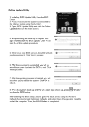
Installing BIOS Update Utility from the DVD Driver. 2. Please make sure the system is connected to download it. Open BIOS Update Utility and click the Online Update button on the main screen. 4. If there is finished, you will show up , press key to proceed. 7. Click Yes to enter BIOS setup. While the system boots up and the full screen logo shows up to request your agreement to restart the computer. After entering the...
Installing BIOS Update Utility from the DVD Driver. 2. Please make sure the system is connected to download it. Open BIOS Update Utility and click the Online Update button on the main screen. 4. If there is finished, you will show up , press key to proceed. 7. Click Yes to enter BIOS setup. While the system boots up and the full screen logo shows up to request your agreement to restart the computer. After entering the...
Update Manual
Page 3
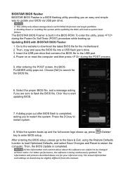
... and single partition. 2. After entering the POST screen, the BIOSFLASHER utility pops out. Press the [Y] key to system boot failure. After entering the BIOS setup, please go to the Save & Exit, using the Restore Defaults function to load Optimized Defaults, and select Save Changes and Reset to start updating BIOS. 7. All the information and content above are for your BIOS via USB pen drive. 1. Power on board may be changed without notice. While the system...
... and single partition. 2. After entering the POST screen, the BIOSFLASHER utility pops out. Press the [Y] key to system boot failure. After entering the BIOS setup, please go to the Save & Exit, using the Restore Defaults function to load Optimized Defaults, and select Save Changes and Reset to start updating BIOS. 7. All the information and content above are for your BIOS via USB pen drive. 1. Power on board may be changed without notice. While the system...
Setup Manual
Page 4
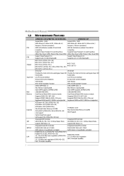
...AMD 64 Architecture enables 32 and 64 bit computing computing Supports Hyper Transport 3.0 and PowerNow Supports Hyper Transport 2.0 and PowerNow Athlon Max. Motherboard Manual 1.3 MOTHERBOARD FEATURES CPU FSB Chipset Super I /O functionality functionality Low Pin Count Interface Low Pin Count Interface Environment Control initiatives Environment Control initiatives H/W Monitor H/W Monitor ITE's "Smart Guardian" function ITE's "Smart Guardian" function DDR2 DIMM Slots x 2 Max Memory Capacity 8GB Each DIMM supports 256MB/512MB/ 1GB/2GB/4GB DDR2 Dual Channel Mode DDR2 memory...
...AMD 64 Architecture enables 32 and 64 bit computing computing Supports Hyper Transport 3.0 and PowerNow Supports Hyper Transport 2.0 and PowerNow Athlon Max. Motherboard Manual 1.3 MOTHERBOARD FEATURES CPU FSB Chipset Super I /O functionality functionality Low Pin Count Interface Low Pin Count Interface Environment Control initiatives Environment Control initiatives H/W Monitor H/W Monitor ITE's "Smart Guardian" function ITE's "Smart Guardian" function DDR2 DIMM Slots x 2 Max Memory Capacity 8GB Each DIMM supports 256MB/512MB/ 1GB/2GB/4GB DDR2 Dual Channel Mode DDR2 memory...
Setup Manual
Page 5
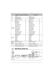
...PCI Express x1 slot x1 PCI slot x2 PCI slot x2 Floppy connector x1 Floppy connector x1 IDE Connector x1 IDE Connector x1 SATA Connector x6 SATA Connector x6 Front Panel Connector x1 Front Panel Connector x1 Front Audio Connector x1 Front Audio Connector x1 CD-in Connector x1 CD-in Connector x1 On Board S/PDIF out connector x1 S/PDIF out connector x1 Connector CPU Fan header x1 CPU Fan header x1 System Fan header x1 System Fan header x1 CMOS clear header x1 CMOS clear header x1 USB connector x3 USB connector x3 Power Connector (24pin) x1 Power...
...PCI Express x1 slot x1 PCI slot x2 PCI slot x2 Floppy connector x1 Floppy connector x1 IDE Connector x1 IDE Connector x1 SATA Connector x6 SATA Connector x6 Front Panel Connector x1 Front Panel Connector x1 Front Audio Connector x1 Front Audio Connector x1 CD-in Connector x1 CD-in Connector x1 On Board S/PDIF out connector x1 S/PDIF out connector x1 Connector CPU Fan header x1 CPU Fan header x1 System Fan header x1 System Fan header x1 CMOS clear header x1 CMOS clear header x1 USB connector x3 USB connector x3 Power Connector (24pin) x1 Power...
Setup Manual
Page 32
Then, save the BIOS file into a USB pen drive or a floppy disk. 3. Select the device contains the BIOS file and press to perform the BIOS update process. 6. Select the proper BIOS file and press then to enter the utility. 5. Press to download the latest BIOS file for the motherboard. 2. A select dialog as the picture on or reset the computer and then press during the Power-On Self Tests (POST) procedure while booting up. Go...
Then, save the BIOS file into a USB pen drive or a floppy disk. 3. Select the device contains the BIOS file and press to perform the BIOS update process. 6. Select the proper BIOS file and press then to enter the utility. 5. Press to download the latest BIOS file for the motherboard. 2. A select dialog as the picture on or reset the computer and then press during the Power-On Self Tests (POST) procedure while booting up. Go...

Setup Manual
Page 33
... 7 cards are used for recovery 4 Flash Programming successful 5 File read error 7 No Flash EPROM detected 10 Flash Erase error 11 Flash Program error 12 "AMIBOOT.ROM" file size error 13 BIOS ROM image mismatch (file layout does not match image present in flash device) POST BIOS Beep Codes Number of Beeps Description 1 Memory refresh timer error 3 Base memory read/write test error 6 Keyboard controller BAT command failed 7 General exception error (processor exception interrupt error) 8 Display memory error (system video adapter) Troubleshooting POST BIOS Beep Codes...
... 7 cards are used for recovery 4 Flash Programming successful 5 File read error 7 No Flash EPROM detected 10 Flash Erase error 11 Flash Program error 12 "AMIBOOT.ROM" file size error 13 BIOS ROM image mismatch (file layout does not match image present in flash device) POST BIOS Beep Codes Number of Beeps Description 1 Memory refresh timer error 3 Base memory read/write test error 6 Keyboard controller BAT command failed 7 General exception error (processor exception interrupt error) 8 Display memory error (system video adapter) Troubleshooting POST BIOS Beep Codes...
Bios Manual
Page 2
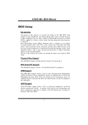
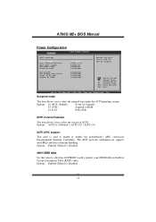
... Green PC specification. It provides ASL code for pow er manag ement and device con figuration capabilities as keyboard, mouse, serial ports and disk drives. ACPI Support AMI ACPI BIOS support Version 1.0/2.0 of the Advanced Power Management (APM) speci fication. T he rest of this manual will to guide you through the options and settings in the AMI BIOS Setup program on this motherboard. Plug and Pla y Support T his AMI BIOS supports Version 1.1&1.2 of Advanced Configuration and Power interface specifi...
... Green PC specification. It provides ASL code for pow er manag ement and device con figuration capabilities as keyboard, mouse, serial ports and disk drives. ACPI Support AMI ACPI BIOS support Version 1.0/2.0 of the Advanced Power Management (APM) speci fication. T he rest of this manual will to guide you through the options and settings in the AMI BIOS Setup program on this motherboard. Plug and Pla y Support T his AMI BIOS supports Version 1.1&1.2 of Advanced Configuration and Power interface specifi...
Bios Manual
Page 4
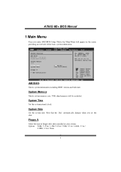
... BIOS SETU P U TILITY PCIPnP Boot Chipset Performance Exit System Overvie w AMI BIOS Version :01. 01.01 Build Date:01/ 01/08 System Memory Size : Use [ENTER], [TAB] or [SHIFT-TAB] to configure system Time. Note that the 'Day' automatically changes when you enter AMI BIOS Setup Utility, the Main Menu will be excluded.. AMI BIOS Shows system information including BIOS version and built date. System Time Set the system internal clock. A760G M2+ BIOS Manual 1 Main Menu...
... BIOS SETU P U TILITY PCIPnP Boot Chipset Performance Exit System Overvie w AMI BIOS Version :01. 01.01 Build Date:01/ 01/08 System Memory Size : Use [ENTER], [TAB] or [SHIFT-TAB] to configure system Time. Note that the 'Day' automatically changes when you enter AMI BIOS Setup Utility, the Main Menu will be excluded.. AMI BIOS Shows system information including BIOS version and built date. System Time Set the system internal clock. A760G M2+ BIOS Manual 1 Main Menu...
Bios Manual
Page 7
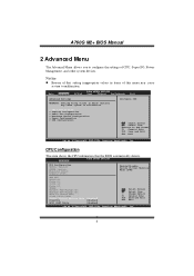
... malfunction. Main Advan ced BIOS SETU P U TILITY PCIPnP Boot Chipset Performance Exit Advanced Setti ngs WARNING: Setti ng wrong values in items of CPU, Super I/O, Power Management, and other system devices. Notice z Beware of that the BIOS automatically detects. Advanced BIOS SETUP UTILITY CPU Configuration Module Version: AGESA Version: Physical Count: Logical Count: Enable/Disable Secure Virtual Machi ne Mode (SVM) AMD CPU Revision: Cache L1: Cache L2: Cache L3: Speed : Current...
... malfunction. Main Advan ced BIOS SETU P U TILITY PCIPnP Boot Chipset Performance Exit Advanced Setti ngs WARNING: Setti ng wrong values in items of CPU, Super I/O, Power Management, and other system devices. Notice z Beware of that the BIOS automatically detects. Advanced BIOS SETUP UTILITY CPU Configuration Module Version: AGESA Version: Physical Count: Logical Count: Enable/Disable Secure Virtual Machi ne Mode (SVM) AMD CPU Revision: Cache L1: Cache L2: Cache L3: Speed : Current...

Bios Manual
Page 8
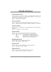
..., American Me gatrends, Inc. 7 Options: Enabled (Default) / Disabled CPU Prefetching T his item controls whether the SRAT is made available to the operating system at boot time and uses the information to enable or disable CPU Prefetching fun ction. Options: Enabled (Default) / Disabled SuperIO Configuration Advan ced BIOS SETU P U TILITY Configure ITE8 718 Super IO Chipse t Onboard Floppy Controller Serial Port1 A ddress Parallel Port Address Parallel Por t Mode Parallel Por t IRQ Keyboard Power On Mouse PowerOn Restore...
..., American Me gatrends, Inc. 7 Options: Enabled (Default) / Disabled CPU Prefetching T his item controls whether the SRAT is made available to the operating system at boot time and uses the information to enable or disable CPU Prefetching fun ction. Options: Enabled (Default) / Disabled SuperIO Configuration Advan ced BIOS SETU P U TILITY Configure ITE8 718 Super IO Chipse t Onboard Floppy Controller Serial Port1 A ddress Parallel Port Address Parallel Por t Mode Parallel Por t IRQ Keyboard Power On Mouse PowerOn Restore...
Bios Manual
Page 9
... to control the keyboard power on the system board and you wish to select the IRQ for the onboard parallel port. Options: Disabled (Default) / Specific Key / Stroke Key 8 Options: DMA3 (Default) / DMA0 / DMA1 Parallel Port IRQ T his item allows you to use it. Options: Enabled (Default) / Disabled Serial Port1 Address Select an address and corresponding interrupt fo r the first and second seri al ports. ECP+EPP Using Parallel port as Enhanced Parallel Port. A760G M2+ BIOS Manual Onboard Floppy Controller Select enabled...
... to control the keyboard power on the system board and you wish to select the IRQ for the onboard parallel port. Options: Disabled (Default) / Specific Key / Stroke Key 8 Options: DMA3 (Default) / DMA0 / DMA1 Parallel Port IRQ T his item allows you to use it. Options: Enabled (Default) / Disabled Serial Port1 Address Select an address and corresponding interrupt fo r the first and second seri al ports. ECP+EPP Using Parallel port as Enhanced Parallel Port. A760G M2+ BIOS Manual Onboard Floppy Controller Select enabled...
Bios Manual
Page 12
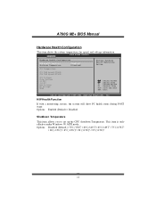
... Megatre nds, Inc. CPU F AN Speed(JCFA N1) SYS F AN Speed(JSFA N1) CPU V oltage Chip Voltage +3.30 V +12.0 V DDR V oltage HT Vo ltage 5VSB S elect Screen S elect Item +- Options: Enabled (Default) / Disabled Shutdow n Temperature T his item shows the system temperature, fan speed, and voltage information. A760G M2+ BIOS Manual Hardware Health Configuration T his item allows you to set up the CPU shutdown T emperature. This item is only effective under Windows 98 ACPI mode.
... Megatre nds, Inc. CPU F AN Speed(JCFA N1) SYS F AN Speed(JSFA N1) CPU V oltage Chip Voltage +3.30 V +12.0 V DDR V oltage HT Vo ltage 5VSB S elect Screen S elect Item +- Options: Enabled (Default) / Disabled Shutdow n Temperature T his item shows the system temperature, fan speed, and voltage information. A760G M2+ BIOS Manual Hardware Health Configuration T his item allows you to set up the CPU shutdown T emperature. This item is only effective under Windows 98 ACPI mode.
Bios Manual
Page 13
.... Options: Enabled (Default) / Disabled 12 Options: Enabled (Default) / Disabled AMI OEMB table Set this value to allow the ACPIBIOS to add a pointer to enable or disable the motherboard's APIC (Advan ced Programmable Interrupt Controller). A760G M2+ BIOS Manual Power Configuration Advanced BIOS S ETUP UTILITY ACPI Settings Suspe nd mode ACPI Version Featu res ACPI APIC support AMI O EMB table Headl ess mode RTC R esume USB W akeup From S3 /S4 Power On by LAN Resum e On RING [ S1 (POS)] [ ACPI v1.0] [ Enabled] [ Enabled] [ Disabled] [ Disabled] [ Disabled] [ Disabled] [ Disabled...
.... Options: Enabled (Default) / Disabled 12 Options: Enabled (Default) / Disabled AMI OEMB table Set this value to allow the ACPIBIOS to add a pointer to enable or disable the motherboard's APIC (Advan ced Programmable Interrupt Controller). A760G M2+ BIOS Manual Power Configuration Advanced BIOS S ETUP UTILITY ACPI Settings Suspe nd mode ACPI Version Featu res ACPI APIC support AMI O EMB table Headl ess mode RTC R esume USB W akeup From S3 /S4 Power On by LAN Resum e On RING [ S1 (POS)] [ ACPI v1.0] [ Enabled] [ Enabled] [ Disabled] [ Disabled] [ Disabled] [ Disabled] [ Disabled...

Bios Manual
Page 15
... legacy support fo r USB devices like the keyboard, mouse, and USB drive. Microso ft DOS or Windows NT). Advanced BIOS SETUP UTILITY USB Configuration Module Version - 2.24.2-13.4 USB Devices Enabled: Legacy USB Support USB 2.0 Controller Mode BIOS EHCI Hand-Off [Enabled] [HiSpeed] [Enabled] > USB Mass Storage Device Configuration Enables support for op erating systems without an EHCI hand-o ff feature. A760G M2+ BIOS Manual USB Configuration T his item allows you to enable support for legacy USB. AUTO option disables legacy support if no USB devices are connected...
... legacy support fo r USB devices like the keyboard, mouse, and USB drive. Microso ft DOS or Windows NT). Advanced BIOS SETUP UTILITY USB Configuration Module Version - 2.24.2-13.4 USB Devices Enabled: Legacy USB Support USB 2.0 Controller Mode BIOS EHCI Hand-Off [Enabled] [HiSpeed] [Enabled] > USB Mass Storage Device Configuration Enables support for op erating systems without an EHCI hand-o ff feature. A760G M2+ BIOS Manual USB Configuration T his item allows you to enable support for legacy USB. AUTO option disables legacy support if no USB devices are connected...

Bios Manual
Page 20
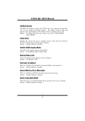
... boot options. Slave / Sec. Slave / USB HDD0 / USB HDD1 / USB HDD2 / Bootable Add-in this sub-menu specify the boot device priority sequence from the available devices. Main Advanced BIOS S ETUP UTILITY PCIPnP Boot Chips et Perfo rmance Exit Boot Settings Conf iguration > Boo t Device Prio rity > Har d Disk Drives > Rem ovable Drives > CD/ DVD Drives Quick Boot [ Enabled] AddOn ROM Display Mode [ Force BIOS] Bootu p Num-Lock [ ON] Inter rupt 19 Captu re [ Enabled] Ignor e Memory Erro r Messages [ Disabled] BOOT SUCCESS BEEP [ Enabled] Spec...
... boot options. Slave / Sec. Slave / USB HDD0 / USB HDD1 / USB HDD2 / Bootable Add-in this sub-menu specify the boot device priority sequence from the available devices. Main Advanced BIOS S ETUP UTILITY PCIPnP Boot Chips et Perfo rmance Exit Boot Settings Conf iguration > Boo t Device Prio rity > Har d Disk Drives > Rem ovable Drives > CD/ DVD Drives Quick Boot [ Enabled] AddOn ROM Display Mode [ Force BIOS] Bootu p Num-Lock [ ON] Inter rupt 19 Captu re [ Enabled] Ignor e Memory Erro r Messages [ Disabled] BOOT SUCCESS BEEP [ Enabled] Spec...
Bios Manual
Page 21
...(Default) / Disabled AddOn ROM Display Mode T his item sets the display mode for option ROM. Options: Disabled (Default) / Enabled BOOT S UCCESS BEEP When this item is set to Enabled, this option will cause an ab ridged version o f the Power On Sel f-T est (POST ) to trap interrupt 19. Options: Enabled (Default) / Disabled Ignore Memory Error Messages When set to arrange the CD/DVD drive boot sequence automatically. Options: Enabled (Default) / Disabled 20 Slave / USB CDROM0 / USB CDROM 1 Quick Boot Enabling this item allows the option ROMs to execute after the system switched...
...(Default) / Disabled AddOn ROM Display Mode T his item sets the display mode for option ROM. Options: Disabled (Default) / Enabled BOOT S UCCESS BEEP When this item is set to Enabled, this option will cause an ab ridged version o f the Power On Sel f-T est (POST ) to trap interrupt 19. Options: Enabled (Default) / Disabled Ignore Memory Error Messages When set to arrange the CD/DVD drive boot sequence automatically. Options: Enabled (Default) / Disabled 20 Slave / USB CDROM0 / USB CDROM 1 Quick Boot Enabling this item allows the option ROMs to execute after the system switched...
Bios Manual
Page 28
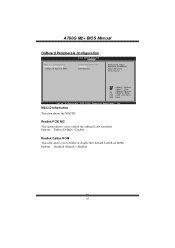
... .xx (C)Copyright 1985-200x, American Me gatrends, Inc. Options: Enable (Default) / Disable Realtek Option ROM T his option allows you to control the onboard LAN controller. MAC ID Information T his item shows the MAC ID. Options: Disabled (Default) / Enabled 27 A760G M2+ BIOS Manual OnBoard Peripherals Configuration BIOS SETU P U TILITY Chipset MAC ID Informa tion Realtek PCIE N IC Realtek Optio n ROM 00-E 0-4C-36-00-04 [Ena ble] [Dis abled] Enable/Disable Onboard Broadcom PCIE Network Controller S elect Screen S elect Item +-
... .xx (C)Copyright 1985-200x, American Me gatrends, Inc. Options: Enable (Default) / Disable Realtek Option ROM T his option allows you to control the onboard LAN controller. MAC ID Information T his item shows the MAC ID. Options: Disabled (Default) / Enabled 27 A760G M2+ BIOS Manual OnBoard Peripherals Configuration BIOS SETU P U TILITY Chipset MAC ID Informa tion Realtek PCIE N IC Realtek Optio n ROM 00-E 0-4C-36-00-04 [Ena ble] [Dis abled] Enable/Disable Onboard Broadcom PCIE Network Controller S elect Screen S elect Item +-

Bios Manual
Page 32
... Screen S elect Item +- Memory interleaving increases bandwidth by turning off unoccupied or inactive DIMM slots. C hange Option F1 G eneral Help F10 S ave and Exit ESC E xit vxx .xx (C)Copyright 1985-200x, American Me gatrends, Inc. Options: Enabled (Default) / Disabled 31 Bank Interleaving Bank Interleaving is an advanced chipset technique used to enable or disable the remapping of the overlapped PCI memory above the total physical memory. Options: Auto (Default) Enable Clock...
... Screen S elect Item +- Memory interleaving increases bandwidth by turning off unoccupied or inactive DIMM slots. C hange Option F1 G eneral Help F10 S ave and Exit ESC E xit vxx .xx (C)Copyright 1985-200x, American Me gatrends, Inc. Options: Enabled (Default) / Disabled 31 Bank Interleaving Bank Interleaving is an advanced chipset technique used to enable or disable the remapping of the overlapped PCI memory above the total physical memory. Options: Auto (Default) Enable Clock...
Bios Manual
Page 37
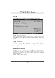
... not set , the "User" will only be able to view configurations but will be able to change them. A760G M2+ BIOS Manual Security T his option allows you to provide/revise supervisor and user password. Options: Disabled (Default) / Enabled 36 If this fun ction is enabled and an attempt is made to write to the boot sector, BIOS will prohibit everyone except the supervisor from making changes using the CMOS Setup Utility.
... not set , the "User" will only be able to view configurations but will be able to change them. A760G M2+ BIOS Manual Security T his option allows you to provide/revise supervisor and user password. Options: Disabled (Default) / Enabled 36 If this fun ction is enabled and an attempt is made to write to the boot sector, BIOS will prohibit everyone except the supervisor from making changes using the CMOS Setup Utility.


