Setup Manual
Page 2
... System Memory 8 2.4 Connectors and Slots 10 Chapter 3: Headers & Jumpers Setup 13 3.1 How to Setup Jumpers 13 3.2 Detail Settings 13 Chapter 4: AMD DUAL Graphics Technology ......... 18 4.1 AMD Dual Graphics Technology Introduction 18 4.2 AMD Dual Graphics Requirement 18 4.3 AMD Dual Graphics Setup 19 Chapter 5: RAID Functions 20 5.1 Operating System 20 5.2 Raid Arrays 20 5.3 How RAID Works 20 Chapter 6: Useful Help 23 6.1 Driver Installation Note 23 6.2 Software 24 6.3 Extra Information 28 6.4 AMI BIOS Beep Code 30 6.5 Troubleshooting 31...
... System Memory 8 2.4 Connectors and Slots 10 Chapter 3: Headers & Jumpers Setup 13 3.1 How to Setup Jumpers 13 3.2 Detail Settings 13 Chapter 4: AMD DUAL Graphics Technology ......... 18 4.1 AMD Dual Graphics Technology Introduction 18 4.2 AMD Dual Graphics Requirement 18 4.3 AMD Dual Graphics Setup 19 Chapter 5: RAID Functions 20 5.1 Operating System 20 5.2 Raid Arrays 20 5.3 How RAID Works 20 Chapter 6: Useful Help 23 6.1 Driver Installation Note 23 6.2 Software 24 6.3 Extra Information 28 6.4 AMI BIOS Beep Code 30 6.5 Troubleshooting 31...
Setup Manual
Page 3
... unfastened small parts inside the case after installation. Before you start installing the motherboard, please make sure you follow the instructions below: „ Prepare a dry and stable working environment with sufficient lighting. „ Always disconnect the computer from power outlet before operation. „ Before you for ATX Case X 1 Installation Guide X 1 User's Manual X1 Fully Setup Driver DVD X1 Note: The package contents may be different due to remove the static...
... unfastened small parts inside the case after installation. Before you start installing the motherboard, please make sure you follow the instructions below: „ Prepare a dry and stable working environment with sufficient lighting. „ Always disconnect the computer from power outlet before operation. „ Before you for ATX Case X 1 Installation Guide X 1 User's Manual X1 Fully Setup Driver DVD X1 Note: The package contents may be different due to remove the static...
Setup Manual
Page 4
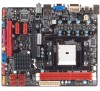
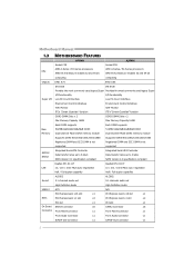
... Manual 1.3 MOTHERBOARD FEATURES A75MH A55MH Socket FM1 Socket FM1 AMD A-Series / E2-Series processors AMD A-Series / E2-Series processors CPU AMD 64 Architecture enables 32 and 64 bit AMD 64 Architecture enables 32 and 64 bit computing computing Chipset AMD A75 AMD A55 ITE 8728 ITE 8728 Provides the most commonly used legacy Super Provides the most commonly used legacy Super I/O functionality I/O functionality Super I/O Low Pin Count Interface Low Pin Count Interface Environment Control initiatives Environment Control initiatives H/W Monitor H/W Monitor ITE's "Smart...
... Manual 1.3 MOTHERBOARD FEATURES A75MH A55MH Socket FM1 Socket FM1 AMD A-Series / E2-Series processors AMD A-Series / E2-Series processors CPU AMD 64 Architecture enables 32 and 64 bit AMD 64 Architecture enables 32 and 64 bit computing computing Chipset AMD A75 AMD A55 ITE 8728 ITE 8728 Provides the most commonly used legacy Super Provides the most commonly used legacy Super I/O functionality I/O functionality Super I/O Low Pin Count Interface Low Pin Count Interface Environment Control initiatives Environment Control initiatives H/W Monitor H/W Monitor ITE's "Smart...
Setup Manual
Page 5
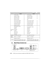
....X devices. 3 A75MH / A55MH A55MH CPU Fan Header x1 System Fan Header x1 CMOS clear Header x1 USB 2.0 Connector x2 N/A Power Connector (24pin) x1 Power Connector (4pin) x1 Consumer IR Connector x1 Printer Port Connector x1 Serial port Connector x1 PS/2 Keyboard / Mouse x1 HDMI Port x1 VGA Port x1 DVI-D Port x1 LAN Port x1 USB 2.0 Port x4 Audio Jack x3 200 mm(W) x 244 mm(L) RAID 0 / 1 / 10 support Windows XP / Vista / 7 Biostar reserves the right to add or remove support for any OS With or without notice. 1.4 REAR PANEL CONNECTORS PS /2 Keyboard...
....X devices. 3 A75MH / A55MH A55MH CPU Fan Header x1 System Fan Header x1 CMOS clear Header x1 USB 2.0 Connector x2 N/A Power Connector (24pin) x1 Power Connector (4pin) x1 Consumer IR Connector x1 Printer Port Connector x1 Serial port Connector x1 PS/2 Keyboard / Mouse x1 HDMI Port x1 VGA Port x1 DVI-D Port x1 LAN Port x1 USB 2.0 Port x4 Audio Jack x3 200 mm(W) x 244 mm(L) RAID 0 / 1 / 10 support Windows XP / Vista / 7 Biostar reserves the right to add or remove support for any OS With or without notice. 1.4 REAR PANEL CONNECTORS PS /2 Keyboard...
Setup Manual
Page 9
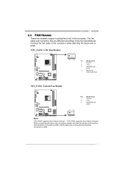
.... 7 Connect the fan cable to the connector while matching the black wire to the fan manufacturer. A75MH / A55MH 2.2 FAN HEADERS These fan headers support cooling-fans built in the computer. When connecting with wires onto connectors, please note that the red wire is the positive and should be connected to pin#2, and the black wire is Ground and should be different according to pin#1. CPU_FAN1: CPU Fan Header 1 4 Pin Assignment 1 Ground 2 +12V 3 FAN RPM rate sense 4 Smart Fan Control...
.... 7 Connect the fan cable to the connector while matching the black wire to the fan manufacturer. A75MH / A55MH 2.2 FAN HEADERS These fan headers support cooling-fans built in the computer. When connecting with wires onto connectors, please note that the red wire is the positive and should be connected to pin#2, and the black wire is Ground and should be different according to pin#1. CPU_FAN1: CPU Fan Header 1 4 Pin Assignment 1 Ground 2 +12V 3 FAN RPM rate sense 4 Smart Fan Control...
Setup Manual
Page 18
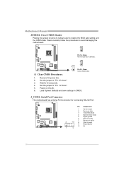
... user to "Pin 2-3 close ". 5. Set the jumper to restore the BIOS safe setting and the CMOS data. Remove AC power line. 2. Pin Assignment 1 Carrier detect 2 Received data 3 Transmitted data 4 Data terminal ready 5 Signal ground 6 Data set ready 7 Request to send 2 10 8 Clear to avoid damaging the motherboard. 3 1 Pin 1-2 Close: Normal Operation (default). 3 ※ Clear CMOS Procedures: 1 3 1 Pin 2-3 Close: Clear CMOS data. 1. Motherboard Manual JCMOS1: Clear CMOS Header Placing the jumper on the AC. 6. Wait for connecting RS-232 Port...
... user to "Pin 2-3 close ". 5. Set the jumper to restore the BIOS safe setting and the CMOS data. Remove AC power line. 2. Pin Assignment 1 Carrier detect 2 Received data 3 Transmitted data 4 Data terminal ready 5 Signal ground 6 Data set ready 7 Request to send 2 10 8 Clear to avoid damaging the motherboard. 3 1 Pin 1-2 Close: Normal Operation (default). 3 ※ Clear CMOS Procedures: 1 3 1 Pin 2-3 Close: Clear CMOS data. 1. Motherboard Manual JCMOS1: Clear CMOS Header Placing the jumper on the AC. 6. Wait for connecting RS-232 Port...
Setup Manual
Page 20
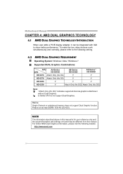
... DG) Note: "Attach Only (No DG)" indicates supported discrete graphics attachment without Dual Graphics. Please use at least DDR3-1333 4G (2G+2G). Notice: Single Channel or unbalanced memory does not support Dual Graphic function. Motherboard Manual CHAPTER 4: AMD DUAL GRAPHICS TECHNOLOGY 4.1 AMD DUAL GRAPHICS TECHNOLOGY INTRODUCTION When user adds a PCIE display adapter, it can be different from this manual. E-Series CPU do not support Dual Graphics. To make the two video devices work simultaneously and normally, please refer to show better...
... DG) Note: "Attach Only (No DG)" indicates supported discrete graphics attachment without Dual Graphics. Please use at least DDR3-1333 4G (2G+2G). Notice: Single Channel or unbalanced memory does not support Dual Graphic function. Motherboard Manual CHAPTER 4: AMD DUAL GRAPHICS TECHNOLOGY 4.1 AMD DUAL GRAPHICS TECHNOLOGY INTRODUCTION When user adds a PCIE display adapter, it can be different from this manual. E-Series CPU do not support Dual Graphics. To make the two video devices work simultaneously and normally, please refer to show better...
Setup Manual
Page 31
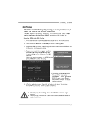
... download the latest BIOS file for the motherboard. 2. A75MH / A55MH BIO-Flasher BIO-Flasher is built in the BIOS chip. Go to the website to perform the BIOS update process. 6. Insert the USB pen drive or the floppy disk that contains the BIOS file to proceed. Press to the USB port or the floppy disk drive. 4. BIOS update completes. Updating BIOS with FAT32/16 format and single partition. Power on the right appears. After the update process, the utility...
... download the latest BIOS file for the motherboard. 2. A75MH / A55MH BIO-Flasher BIO-Flasher is built in the BIOS chip. Go to the website to perform the BIOS update process. 6. Insert the USB pen drive or the floppy disk that contains the BIOS file to proceed. Press to the USB port or the floppy disk drive. 4. BIOS update completes. Updating BIOS with FAT32/16 format and single partition. Power on the right appears. After the update process, the utility...
Setup Manual
Page 32
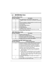
... are used for recovery 4 Flash Programming successful 5 File read error 7 No Flash EPROM detected 10 Flash Erase error 11 Flash Program error 12 "AMIBOOT.ROM" file size error 13 BIOS ROM image mismatch (file layout does not match image present in flash device) POST BIOS Beep Codes Number of Beeps Description 1 Memory refresh timer error 3 Base memory read/write test error 6 Keyboard controller BAT command failed 7 General exception error (processor exception interrupt error) 8 Display memory error (system video adapter) Troubleshooting POST BIOS Beep Codes Number...
... are used for recovery 4 Flash Programming successful 5 File read error 7 No Flash EPROM detected 10 Flash Erase error 11 Flash Program error 12 "AMIBOOT.ROM" file size error 13 BIOS ROM image mismatch (file layout does not match image present in flash device) POST BIOS Beep Codes Number of Beeps Description 1 Memory refresh timer error 3 Base memory read/write test error 6 Keyboard controller BAT command failed 7 General exception error (processor exception interrupt error) 8 Display memory error (system video adapter) Troubleshooting POST BIOS Beep Codes Number...
Bios Setup
Page 2
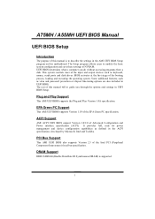
... describe the settings in UEFI BIOS Setup. Plug and Play Support This AMI UEFI BIOS supports the Plug and Play Version 1.0A specification. This system controls most of this motherboard. UEFI BIOS determines what a computer can do without accessing programs from a disk. The rest of the input and output devices such as keyboard, mouse, serial ports and disk drives. It provides ASL code for power management and device configuration capabilities as virus and password protection or chipset fine-tuning options are...
... describe the settings in UEFI BIOS Setup. Plug and Play Support This AMI UEFI BIOS supports the Plug and Play Version 1.0A specification. This system controls most of this motherboard. UEFI BIOS determines what a computer can do without accessing programs from a disk. The rest of the input and output devices such as keyboard, mouse, serial ports and disk drives. It provides ASL code for power management and device configuration capabilities as virus and password protection or chipset fine-tuning options are...
Bios Setup
Page 3
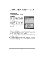
... UEFI BIOS supports AMD CPU. In the UEFI BIOS setup utility, you can use these keys to select item and change the settings. Navigation Keys for that may be slightly different from this manual. Use Load Setup Default under the Exit Menu. z The content of the selected item. Using Setup When starting up the computer, press during the Power-On Self-Test (POST) to ensure system's compatibility and stability. The actual UEFI BIOS information and settings on board may be changed...
... UEFI BIOS supports AMD CPU. In the UEFI BIOS setup utility, you can use these keys to select item and change the settings. Navigation Keys for that may be slightly different from this manual. Use Load Setup Default under the Exit Menu. z The content of the selected item. Using Setup When starting up the computer, press during the Power-On Self-Test (POST) to ensure system's compatibility and stability. The actual UEFI BIOS information and settings on board may be changed...
Bios Setup
Page 7
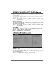
... ACPI sleep state the system will enter when the SUSPEND button is pressed. Options: S3 (Suspend to LO State; Disables ASPM. A75MH / A55MH UEFI BIOS Manual Maximum Payload This item sets Maximum Payload of PCI Express Device or allows System BIOS to select the value. Options: Auto (Default) / 128 Bytes / 256 Bytes / 512 Bytes / 1024 Bytes / 2048 Bytes / 4096 Bytes ASPM Support This item sets the ASPM Level: Force LO - BIOS auto configures; Options: Auto (Default...
... ACPI sleep state the system will enter when the SUSPEND button is pressed. Options: S3 (Suspend to LO State; Disables ASPM. A75MH / A55MH UEFI BIOS Manual Maximum Payload This item sets Maximum Payload of PCI Express Device or allows System BIOS to select the value. Options: Auto (Default) / 128 Bytes / 256 Bytes / 512 Bytes / 1024 Bytes / 2048 Bytes / 4096 Bytes ASPM Support This item sets the ASPM Level: Force LO - BIOS auto configures; Options: Auto (Default...
Bios Setup
Page 9
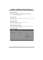
Options: Wake Key (Default) / Power Key / Ctrl+F1 / Ctrl+F2 / Ctrl+F3 / Ctrl +F4 / Ctrl+F5 / Ctrl+F6 Specific Key Enter This item will show only when Keyboard PowerOn is set "Specific Key." Options: Disabled (Default) / Enabled CPU Configuration 8 Options: Disabled (Default) / Enabled USB Device Wakeup from S3/S4 This item allows you to enable or disabled the USB resume from S3/S4 function. PS2 Mouse PowerOn This item allows you to control the mouse power on function. A75MH / A55MH UEFI BIOS Manual Stroke Keys Selected...
Options: Wake Key (Default) / Power Key / Ctrl+F1 / Ctrl+F2 / Ctrl+F3 / Ctrl +F4 / Ctrl+F5 / Ctrl+F6 Specific Key Enter This item will show only when Keyboard PowerOn is set "Specific Key." Options: Disabled (Default) / Enabled CPU Configuration 8 Options: Disabled (Default) / Enabled USB Device Wakeup from S3/S4 This item allows you to enable or disabled the USB resume from S3/S4 function. PS2 Mouse PowerOn This item allows you to control the mouse power on function. A75MH / A55MH UEFI BIOS Manual Stroke Keys Selected...
Bios Setup
Page 10
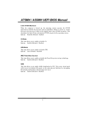
... system executes the CPUID instruction to enable AMD virtualization in CPU. Options: Enabled (Default) / Disabled CPB Mode This item allows you to enable or disable CPB. This secure virtual mode will let your run multiple OS (guest) on the same physical hardware by decoupling OS and physical hardware with the hypervisor layer. Before it must first query the processor to enable or disable C6. Options: Auto (Default) / Disabled AMD PowerNow function This...
... system executes the CPUID instruction to enable AMD virtualization in CPU. Options: Enabled (Default) / Disabled CPB Mode This item allows you to enable or disable CPB. This secure virtual mode will let your run multiple OS (guest) on the same physical hardware by decoupling OS and physical hardware with the hypervisor layer. Before it must first query the processor to enable or disable C6. Options: Auto (Default) / Disabled AMD PowerNow function This...
Bios Setup
Page 13
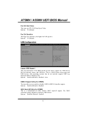
... hand-off support. Microsoft DOS or Windows NT). Options: 30 (Default) USB Configuration Legacy USB Support This item determines if the BIOS should be claimed by XHCI driver. Options: Disabled (Default) / Enabled 12 The XHCI ownership change should provide legacy support for USB devices like the keyboard, mouse, and USB drive. A75MH / A55MH UEFI BIOS Manual Fan Ctrl Start Value This item sets CPU FAN Start Speed Value. Options: 50 (Default) Fan Ctrl Sensitive The bigger the numeral is, the higher the FAN speed is a useful feature when using such USB devices with...
... hand-off support. Microsoft DOS or Windows NT). Options: 30 (Default) USB Configuration Legacy USB Support This item determines if the BIOS should be claimed by XHCI driver. Options: Disabled (Default) / Enabled 12 The XHCI ownership change should provide legacy support for USB devices like the keyboard, mouse, and USB drive. A75MH / A55MH UEFI BIOS Manual Fan Ctrl Start Value This item sets CPU FAN Start Speed Value. Options: 50 (Default) Fan Ctrl Sensitive The bigger the numeral is, the higher the FAN speed is a useful feature when using such USB devices with...
Bios Setup
Page 19
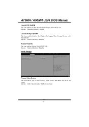
Options: Enabled (Default) / Disabled Realtek PCIE NIC This item enables/disables Realtek PCIE NIC. Options: Enabled (Default) / Disabled North Bridge Primary Video Device This item allows you to select Primary Video Device that BIOS will use to for Legacy Network Devices. A75MH / A55MH UEFI BIOS Manual Launch PXE OpROM This item enables/disables Boot Option for output. Options: IGD Video (Default) / NB PCIe slot Video 18 Options: Disabled (Default) / Enabled Launch Storage OpROM This item enables/disables Boot Option for Legacy Mass Storage Devices with Option ROM.
Options: Enabled (Default) / Disabled Realtek PCIE NIC This item enables/disables Realtek PCIE NIC. Options: Enabled (Default) / Disabled North Bridge Primary Video Device This item allows you to select Primary Video Device that BIOS will use to for Legacy Network Devices. A75MH / A55MH UEFI BIOS Manual Launch PXE OpROM This item enables/disables Boot Option for output. Options: IGD Video (Default) / NB PCIe slot Video 18 Options: Disabled (Default) / Enabled Launch Storage OpROM This item enables/disables Boot Option for Legacy Mass Storage Devices with Option ROM.
Bios Setup
Page 20
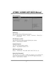
... Graphics This item set PCIe speed power policy. A75MH / A55MH UEFI BIOS Manual GFX Configuation PSPP Policy This item allows you to enable or disable the remapping of the overlapped PCI memory above the total physical memory. Only 64-bit OS supports this function. Options: Auto (Default) / Disabled / Force UMA Frame buffer Size Options: 384M (Default) / 32M / 64M / 128M / 256M / 512M / 1G / 2G Memory Hole Remapping This item allows you to enable or disable GFX HD Audio controller. Options...
... Graphics This item set PCIe speed power policy. A75MH / A55MH UEFI BIOS Manual GFX Configuation PSPP Policy This item allows you to enable or disable the remapping of the overlapped PCI memory above the total physical memory. Only 64-bit OS supports this function. Options: Auto (Default) / Disabled / Force UMA Frame buffer Size Options: 384M (Default) / 32M / 64M / 128M / 256M / 512M / 1G / 2G Memory Hole Remapping This item allows you to enable or disable GFX HD Audio controller. Options...
Bios Setup
Page 22
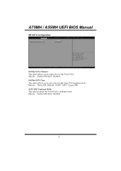
Options: Enabled (Default) / Disabled OnChip SATA Type This option allows you to select the on -chip Serial ATA. Options: Enabled (Default) / Disabled 21 A75MH / A55MH UEFI BIOS Manual SB SAT A Configuration S OnChip SATA Channel This option allows you to enable the on -chip Serial ATA operation mode. Options: Native IDE (Default) / RAID / AHCI / Legacy IDE SATA IDE Combined Mode This option controls the SATA/PATA combined mode.
Options: Enabled (Default) / Disabled OnChip SATA Type This option allows you to select the on -chip Serial ATA. Options: Enabled (Default) / Disabled 21 A75MH / A55MH UEFI BIOS Manual SB SAT A Configuration S OnChip SATA Channel This option allows you to enable the on -chip Serial ATA operation mode. Options: Native IDE (Default) / RAID / AHCI / Legacy IDE SATA IDE Combined Mode This option controls the SATA/PATA combined mode.
Bios Setup
Page 27
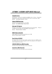
.../DVD ROM Drive BBS Priorities This item sets the order of devices installed in this option is useful when any RT code is the software interrupt that appears on the screen depends on the number of the legacy devices in the system. A75MH / A55MH UEFI BIOS Manual GateA20 Active Upon Request - this group. Options: Disabled (Default) / Enabled BIOS Flash protection While enabled, it can be disabled using BIOS services. Options: Enabled (Default) / Disabled Boot Option #1/#2/#3 The items specify the boot device priority sequence from the available devices...
.../DVD ROM Drive BBS Priorities This item sets the order of devices installed in this option is useful when any RT code is the software interrupt that appears on the screen depends on the number of the legacy devices in the system. A75MH / A55MH UEFI BIOS Manual GateA20 Active Upon Request - this group. Options: Disabled (Default) / Enabled BIOS Flash protection While enabled, it can be disabled using BIOS services. Options: Enabled (Default) / Disabled Boot Option #1/#2/#3 The items specify the boot device priority sequence from the available devices...
Bios Setup
Page 35
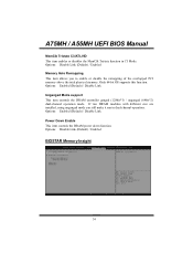
... DRAM power down function. If two DRAM modules with different size are installed, using unganged mode can still make it run in C3 Mode. Options: Disable Link (Default) / Enabled BIOSTAR Memory Insight 34 Options: Enabled (Default) / Disable Link Unganged Mode support This item controls the DRAM controller ganged (128bit*1) / unganged (64bit*2) dual-channel operation mode. A75MH / A55MH UEFI BIOS Manual MemClk Tristate C3/ATLVID This item enables or disables the MemClk Tristate function in dual-channel operation. Only 64-bit OS supports this function. Options: Disable Link (Default...
... DRAM power down function. If two DRAM modules with different size are installed, using unganged mode can still make it run in C3 Mode. Options: Disable Link (Default) / Enabled BIOSTAR Memory Insight 34 Options: Enabled (Default) / Disable Link Unganged Mode support This item controls the DRAM controller ganged (128bit*1) / unganged (64bit*2) dual-channel operation mode. A75MH / A55MH UEFI BIOS Manual MemClk Tristate C3/ATLVID This item enables or disables the MemClk Tristate function in dual-channel operation. Only 64-bit OS supports this function. Options: Disable Link (Default...


