Setup Manual
Page 1
... essenziali richiesti dalle direttive 2004/108/CE, 2006/95/CE e 1999/05/CE quando ad esso applicabili Short Declaration of this user's manual is complying with the laws in this product is subject to be changed without notice and we will not occur in accordance with the ...frequency energy and, if not installed and used in a particular installation. The vendor makes no guarantee that interference will not be applied A75MH / A55MH Setup Manual FCC Information and Copyright This equipment has been tested and found to comply with the limits of a Class B digital device, pursuant ...
... essenziali richiesti dalle direttive 2004/108/CE, 2006/95/CE e 1999/05/CE quando ad esso applicabili Short Declaration of this user's manual is complying with the laws in this product is subject to be changed without notice and we will not occur in accordance with the ...frequency energy and, if not installed and used in a particular installation. The vendor makes no guarantee that interference will not be applied A75MH / A55MH Setup Manual FCC Information and Copyright This equipment has been tested and found to comply with the limits of a Class B digital device, pursuant ...
Setup Manual
Page 3
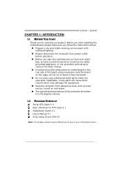
... sufficient lighting. „ Always disconnect the computer from power outlet before operation. „ Before you for ATX Case X 1 Installation Guide X 1 User's Manual X1 Fully Setup Driver DVD X1 Note: The package contents may be different due to bend or flex the board. „ Do not leave any... remove the static charge. „ Avoid touching the components on the edge, do not try to area or your motherboard version. 1 CHAPTER 1: INTRODUCTION A75MH / A55MH 1.1 BEFORE YOU START Thank you take the motherboard out from dangerous area, such as heat source, humid air and water. „ The...
... sufficient lighting. „ Always disconnect the computer from power outlet before operation. „ Before you for ATX Case X 1 Installation Guide X 1 User's Manual X1 Fully Setup Driver DVD X1 Note: The package contents may be different due to bend or flex the board. „ Do not leave any... remove the static charge. „ Avoid touching the components on the edge, do not try to area or your motherboard version. 1 CHAPTER 1: INTRODUCTION A75MH / A55MH 1.1 BEFORE YOU START Thank you take the motherboard out from dangerous area, such as heat source, humid air and water. „ The...
Setup Manual
Page 4
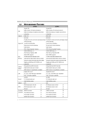
Motherboard Manual 1.3 MOTHERBOARD FEATURES A75MH A55MH Socket FM1 Socket FM1 AMD A-Series / E2-Series processors AMD A-Series / E2-Series processors CPU AMD 64 Architecture enables 32 and 64 bit AMD ...
Motherboard Manual 1.3 MOTHERBOARD FEATURES A75MH A55MH Socket FM1 Socket FM1 AMD A-Series / E2-Series processors AMD A-Series / E2-Series processors CPU AMD 64 Architecture enables 32 and 64 bit AMD ...
Setup Manual
Page 6
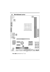
HDMI1 Motherboard Manual 1.5 MOTHERBOARD LAYOUT USB_KBMS1 ATXP WR2 CPU_FAN1 DVI1 DDR3_ A1 DDR3_ B1 VGA1 ATX PWR1 RJ45USB1 LAN AUDIO1 JS PDIF OUT1 PEX16_1 Super I/O PEX1_1 BAT1 PEX1_2 BIOS AMD A75/ A55 SATA4 SATA5 SATA6 Codec F_ AUDIO1 J_COM1 PCI1 SY S_FAN1 (A75MH) F_USB2 SATA3 SATA2 SATA1 J_PRIN T1 CIR1 JFRONT_USB3_1 JCMOS1 F_USB1 PANEL1 Note: ■ represents the 1st pin. 4
HDMI1 Motherboard Manual 1.5 MOTHERBOARD LAYOUT USB_KBMS1 ATXP WR2 CPU_FAN1 DVI1 DDR3_ A1 DDR3_ B1 VGA1 ATX PWR1 RJ45USB1 LAN AUDIO1 JS PDIF OUT1 PEX16_1 Super I/O PEX1_1 BAT1 PEX1_2 BIOS AMD A75/ A55 SATA4 SATA5 SATA6 Codec F_ AUDIO1 J_COM1 PCI1 SY S_FAN1 (A75MH) F_USB2 SATA3 SATA2 SATA1 J_PRIN T1 CIR1 JFRONT_USB3_1 JCMOS1 F_USB1 PANEL1 Note: ■ represents the 1st pin. 4
Setup Manual
Page 8
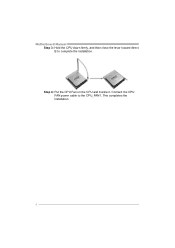
This completes the installation. 6 Connect the CPU FAN power cable to complete the installation. Step 4: Put the CPU Fan on the CPU and buckle it. Motherboard Manual Step 3: Hold the CPU down firmly, and then close the lever toward direct B to the CPU_FAN1.
This completes the installation. 6 Connect the CPU FAN power cable to complete the installation. Step 4: Put the CPU Fan on the CPU and buckle it. Motherboard Manual Step 3: Hold the CPU down firmly, and then close the lever toward direct B to the CPU_FAN1.
Setup Manual
Page 10
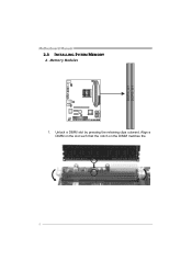
Align a DIMM on the slot such that the notch on the DIMM matches the break on the Slot. 8 Unlock a DIMM slot by pressing the retaining clips outward. Memory Modules 1. DDR3_A 1 DDR3_B 1 Motherboard Manual 2.3 INSTALLING SYSTEM MEMORY A.
Align a DIMM on the slot such that the notch on the DIMM matches the break on the Slot. 8 Unlock a DIMM slot by pressing the retaining clips outward. Memory Modules 1. DDR3_A 1 DDR3_B 1 Motherboard Manual 2.3 INSTALLING SYSTEM MEMORY A.
Setup Manual
Page 12
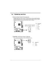
Motherboard Manual 2.4 CONNECTORS AND SLOTS SATA1~SATA6: Serial ATA Connectors A75MH/A55MH has a PCI to CPU power circuit. 14 23 Pin Assignment 1 +12V 2 +12V 3 Ground 4 Ground 10 A55MH satisfies the SATA 2.0 spec and with transfer rate of 6.0Gb/s; A75MH satisfies the SATA 3.0 spec and with 6 channels SATA interface. Pin Assignment 1 Ground SA TA4 SATA 5 SATA 6 2 TX+ SA TA3 S ATA2 SATA1 3 TX- 4 Ground 7 5 RX- 6 RX+ 4 7 Ground 1 ATXPWR2: ATX Power Source Connector This connector will provide +12V to SATA Controller with transfer rate of 3.0Gb/s.
Motherboard Manual 2.4 CONNECTORS AND SLOTS SATA1~SATA6: Serial ATA Connectors A75MH/A55MH has a PCI to CPU power circuit. 14 23 Pin Assignment 1 +12V 2 +12V 3 Ground 4 Ground 10 A55MH satisfies the SATA 2.0 spec and with transfer rate of 6.0Gb/s; A75MH satisfies the SATA 3.0 spec and with 6 channels SATA interface. Pin Assignment 1 Ground SA TA4 SATA 5 SATA 6 2 TX+ SA TA3 S ATA2 SATA1 3 TX- 4 Ground 7 5 RX- 6 RX+ 4 7 Ground 1 ATXPWR2: ATX Power Source Connector This connector will provide +12V to SATA Controller with transfer rate of 3.0Gb/s.
Setup Manual
Page 14
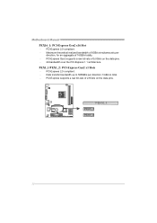
PCI-Express supports a raw bit-rate of 5.0Gb/s on the data pins. PEX1_1/PEX1_2: PCI-Express Gen2 x1 Slots - PCI-Express 2.0 compliant. - PCI-Express Gen2 supports a raw bit-rate of 2.5Gb/s on the data pins. - 2X bandwidth over the PCI-Express 1.1 architecture. PCI-Express 2.0 compliant. - Data transfer bandwidth up to 500MB/s per direction, for an aggregate of 16GB/s totally. - PEX16_1 PEX1_1 PEX1_2 12 Maximum theoretical realized bandwidth of 8GB/s simultaneously per direction; 1GB/s in total. - Motherboard Manual PEX16_1: PCI-Express Gen2 x16 Slot -
PCI-Express supports a raw bit-rate of 5.0Gb/s on the data pins. PEX1_1/PEX1_2: PCI-Express Gen2 x1 Slots - PCI-Express 2.0 compliant. - PCI-Express Gen2 supports a raw bit-rate of 2.5Gb/s on the data pins. - 2X bandwidth over the PCI-Express 1.1 architecture. PCI-Express 2.0 compliant. - Data transfer bandwidth up to 500MB/s per direction, for an aggregate of 16GB/s totally. - PEX16_1 PEX1_1 PEX1_2 12 Maximum theoretical realized bandwidth of 8GB/s simultaneously per direction; 1GB/s in total. - Motherboard Manual PEX16_1: PCI-Express Gen2 x16 Slot -
Setup Manual
Page 16
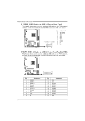
... Assignment 1 +5V (fused) 2 +5V (fused) 3 USB4 USB5 USB+ 6 USB+ 7 Ground 8 Ground 9 NC 10 Key 1 9 JFRONT_USB3_1: Header for USB 2.0 Ports at Front Panel (A75MH) This header allows user to connect additional USB cable on the PC front panel, and also can be connected with internal USB devices, like USB...Assignment 11 D2+ 12 D2- 13 Ground 14 SSTX2+ 15 SSTX2- 16 Ground 17 SSRX2+ 18 SSRX2- 19 VBUS1 20 Key 14 Motherboard Manual F_USB1/F_USB2: Headers for USB 3.0 Ports at Front Panel This header allows user to connect additional USB cable on the PC front panel, and...
... Assignment 1 +5V (fused) 2 +5V (fused) 3 USB4 USB5 USB+ 6 USB+ 7 Ground 8 Ground 9 NC 10 Key 1 9 JFRONT_USB3_1: Header for USB 2.0 Ports at Front Panel (A75MH) This header allows user to connect additional USB cable on the PC front panel, and also can be connected with internal USB devices, like USB...Assignment 11 D2+ 12 D2- 13 Ground 14 SSTX2+ 15 SSTX2- 16 Ground 17 SSRX2+ 18 SSRX2- 19 VBUS1 20 Key 14 Motherboard Manual F_USB1/F_USB2: Headers for USB 3.0 Ports at Front Panel This header allows user to connect additional USB cable on the PC front panel, and...
Setup Manual
Page 18
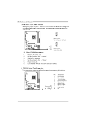
... safe setting and the CMOS data. Set the jumper to send 9 Ring indicator 10 NC 1 9 16 Load Optimal Defaults and save settings in CMOS. Motherboard Manual JCMOS1: Clear CMOS Header Placing the jumper on the AC. 6. Pin Assignment 1 Carrier detect 2 Received data 3 Transmitted data 4 Data terminal ready 5 Signal ground 6 Data set...
... safe setting and the CMOS data. Set the jumper to send 9 Ring indicator 10 NC 1 9 16 Load Optimal Defaults and save settings in CMOS. Motherboard Manual JCMOS1: Clear CMOS Header Placing the jumper on the AC. 6. Pin Assignment 1 Carrier detect 2 Received data 3 Transmitted data 4 Data terminal ready 5 Signal ground 6 Data set...
Setup Manual
Page 20
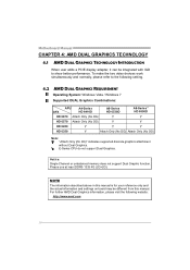
... Graphic function. To make the two video devices work simultaneously and normally, please refer to show better performance. NOTE The information described above in this manual. Motherboard Manual CHAPTER 4: AMD DUAL GRAPHICS TECHNOLOGY 4.1 AMD DUAL GRAPHICS TECHNOLOGY INTRODUCTION When user adds a PCIE display adapter, it can be different from this...
... Graphic function. To make the two video devices work simultaneously and normally, please refer to show better performance. NOTE The information described above in this manual. Motherboard Manual CHAPTER 4: AMD DUAL GRAPHICS TECHNOLOGY 4.1 AMD DUAL GRAPHICS TECHNOLOGY INTRODUCTION When user adds a PCIE display adapter, it can be different from this...
Setup Manual
Page 22
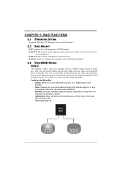
This technique reduces overall disk access time and offers high bandwidth. Motherboard Manual CHAPTER 5: RAID FUNCTIONS 5.1 OPERATING SYSTEM Supports Windows XP, Windows Vista, and Windows 7. 5.2 RAID ARRAYS RAID supports the following types of the RAID set based on ...
This technique reduces overall disk access time and offers high bandwidth. Motherboard Manual CHAPTER 5: RAID FUNCTIONS 5.1 OPERATING SYSTEM Supports Windows XP, Windows Vista, and Windows 7. 5.2 RAID ARRAYS RAID supports the following types of the RAID set based on ...
Setup Manual
Page 23
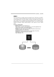
... media. Features and Benefits Drives: Minimum 2, and maximum is 2. Uses: RAID 1 is ideal for small databases or any other application that eliminates tedious manual backups to the other drive. Drawbacks: Requires 2 drives for high-availability solutions, or as a form of a hardware failure. Performance is impaired during drive rebuilds...
... media. Features and Benefits Drives: Minimum 2, and maximum is 2. Uses: RAID 1 is ideal for small databases or any other application that eliminates tedious manual backups to the other drive. Drawbacks: Requires 2 drives for high-availability solutions, or as a form of a hardware failure. Performance is impaired during drive rebuilds...
Setup Manual
Page 24
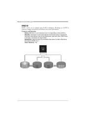
... platform. Benefits: Optimizes for both fault tolerance and performance, allowing for improved resiliency, performance and rebuild performance. May be stripped using RAID 0 techniques. Motherboard Manual RAID 10: RAID 1 drives can be simultaneously used with other RAID levels in a RAID 10 solution for automatic redundancy.
... platform. Benefits: Optimizes for both fault tolerance and performance, allowing for improved resiliency, performance and rebuild performance. May be stripped using RAID 0 techniques. Motherboard Manual RAID 10: RAID 1 drives can be simultaneously used with other RAID levels in a RAID 10 solution for automatic redundancy.
Setup Manual
Page 25
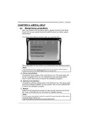
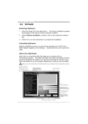
... execute the file SETUP.EXE under your optical drive. Please download the latest version of Acrobat Reader software from the paperback manual, we also provide manual in the Driver CD. Note: If this window didn't show up after you installed your operating system, please insert the...system. Driver Installation To install the driver, please click on the Software icon. Click on each software title to open the manual file. CHAPTER 6: USEFUL HELP A75MH / A55MH 6.1 DRIVER INSTALLATION NOTE After you insert the CD The setup guide will auto detect your motherboard and operating system....
... execute the file SETUP.EXE under your optical drive. Please download the latest version of Acrobat Reader software from the paperback manual, we also provide manual in the Driver CD. Note: If this window didn't show up after you installed your operating system, please insert the...system. Driver Installation To install the driver, please click on the Software icon. Click on each software title to open the manual file. CHAPTER 6: USEFUL HELP A75MH / A55MH 6.1 DRIVER INSTALLATION NOTE After you insert the CD The setup guide will auto detect your motherboard and operating system....
Setup Manual
Page 26
... name of the memor y module manufacturer. This bl ock will see the software icon "eHOT Line" / "BIOS Update" appears on the respective software title. 3. Motherboard Manual 6.2 SOFTWARE Installing Software 1. Save these information to our tech-support department to contact with our Tech-Support system. Provide the name of your system. *Select...
... name of the memor y module manufacturer. This bl ock will see the software icon "eHOT Line" / "BIOS Update" appears on the respective software title. 3. Motherboard Manual 6.2 SOFTWARE Installing Software 1. Save these information to our tech-support department to contact with our Tech-Support system. Provide the name of your system. *Select...
Setup Manual
Page 28
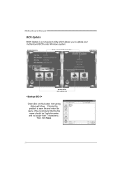
Choose the position to a .bin file Update BIOS with a BIOS file Once click on this button, the saving dialog will show. AWARD BIOS Show current BIOS information AMI BIOS Clear CMOS function (Only for AWARD BIOS) Save current BIOS to save file and enter file name. (We recommend that the file name should be English/number and no longer than 7 characters.) Then click Save. 26 Motherboard Manual BIOS Update BIOS Update is a convenient utility which allows you to update your motherboard BIOS under Windows system.
Choose the position to a .bin file Update BIOS with a BIOS file Once click on this button, the saving dialog will show. AWARD BIOS Show current BIOS information AMI BIOS Clear CMOS function (Only for AWARD BIOS) Save current BIOS to save file and enter file name. (We recommend that the file name should be English/number and no longer than 7 characters.) Then click Save. 26 Motherboard Manual BIOS Update BIOS Update is a convenient utility which allows you to update your motherboard BIOS under Windows system.
Setup Manual
Page 29
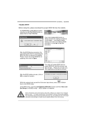
... applications during this process. The utility will show for your reference only. For better performance, the software is completed. A75MH / A55MH Before doing this, please download the proper BIOS file from this manual. 27 The information and pictures described above about the software are for requesting the BIOS file which is going...
... applications during this process. The utility will show for your reference only. For better performance, the software is completed. A75MH / A55MH Before doing this, please download the proper BIOS file from this manual. 27 The information and pictures described above about the software are for requesting the BIOS file which is going...

Setup Manual
Page 30
...) 2. Wait for seconds. 2. Remove the power cord from power supply for seconds. 3. Wait for seconds, that means the CPU protection function has been activated. Motherboard Manual 6.3 EXTRA INFORMATION CPU Overheated If the system shutdown automatically after power on system for seconds. 3. When the CPU is rotated normally. 3. CPU fan is over...
...) 2. Wait for seconds. 2. Remove the power cord from power supply for seconds. 3. Wait for seconds, that means the CPU protection function has been activated. Motherboard Manual 6.3 EXTRA INFORMATION CPU Overheated If the system shutdown automatically after power on system for seconds. 3. When the CPU is rotated normally. 3. CPU fan is over...
Setup Manual
Page 32
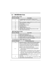
Motherboard Manual 6.4 AMI BIOS BEEP CODE Boot Block Beep Codes Number of Beeps Description 1 No media present. (Insert diskette in floppy drive A:) 2 "AMIBOOT.ROM" file not found ...
Motherboard Manual 6.4 AMI BIOS BEEP CODE Boot Block Beep Codes Number of Beeps Description 1 No media present. (Insert diskette in floppy drive A:) 2 "AMIBOOT.ROM" file not found ...

