Setup Manual
Page 2
Table of Contents Chapter 1: Introduction 1 1.1 Before You Start 1 1.2 Package Checklist 1 1.3 Motherboard Features 2 1.4 Rear Panel Connectors 3 1.5 Motherboard Layout 4 Chapter 2: Hardware Installation 5 2.1 Installing Central Processing Unit (CPU 5 2.2 FAN Headers 7 2.3 Installing System Memory 8 2.4 Connectors and Slots 10 Chapter 3: Headers & Jumpers Setup 13 3.1 How to ...
Table of Contents Chapter 1: Introduction 1 1.1 Before You Start 1 1.2 Package Checklist 1 1.3 Motherboard Features 2 1.4 Rear Panel Connectors 3 1.5 Motherboard Layout 4 Chapter 2: Hardware Installation 5 2.1 Installing Central Processing Unit (CPU 5 2.2 FAN Headers 7 2.3 Installing System Memory 8 2.4 Connectors and Slots 10 Chapter 3: Headers & Jumpers Setup 13 3.1 How to ...
Setup Manual
Page 3
... computer from anti-static bag, ground yourself properly by touching any unfastened small parts inside the case after installation. CHAPTER 1: INTRODUCTION A75MH / A55MH 1.1 BEFORE YOU START Thank you take the motherboard out from dangerous area, such as heat source, humid air and water. „ The operating temperatures of the board unless necessary...
... computer from anti-static bag, ground yourself properly by touching any unfastened small parts inside the case after installation. CHAPTER 1: INTRODUCTION A75MH / A55MH 1.1 BEFORE YOU START Thank you take the motherboard out from dangerous area, such as heat source, humid air and water. „ The operating temperatures of the board unless necessary...
Setup Manual
Page 4
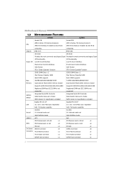
Motherboard Manual 1.3 MOTHERBOARD FEATURES A75MH A55MH Socket FM1 Socket FM1 AMD A-Series / E2-Series processors AMD A-Series / E2-Series processors CPU AMD 64 Architecture enables 32 and 64 bit AMD ...
Motherboard Manual 1.3 MOTHERBOARD FEATURES A75MH A55MH Socket FM1 Socket FM1 AMD A-Series / E2-Series processors AMD A-Series / E2-Series processors CPU AMD 64 Architecture enables 32 and 64 bit AMD ...
Setup Manual
Page 6
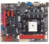
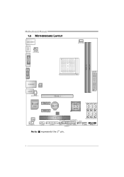
HDMI1 Motherboard Manual 1.5 MOTHERBOARD LAYOUT USB_KBMS1 ATXP WR2 CPU_FAN1 DVI1 DDR3_ A1 DDR3_ B1 VGA1 ATX PWR1 RJ45USB1 LAN AUDIO1 JS PDIF OUT1 PEX16_1 Super I/O PEX1_1 BAT1 PEX1_2 BIOS AMD A75/ A55 SATA4 SATA5 SATA6 Codec F_ AUDIO1 J_COM1 PCI1 SY S_FAN1 (A75MH) F_USB2 SATA3 SATA2 SATA1 J_PRIN T1 CIR1 JFRONT_USB3_1 JCMOS1 F_USB1 PANEL1 Note: ■ represents the 1st pin. 4
HDMI1 Motherboard Manual 1.5 MOTHERBOARD LAYOUT USB_KBMS1 ATXP WR2 CPU_FAN1 DVI1 DDR3_ A1 DDR3_ B1 VGA1 ATX PWR1 RJ45USB1 LAN AUDIO1 JS PDIF OUT1 PEX16_1 Super I/O PEX1_1 BAT1 PEX1_2 BIOS AMD A75/ A55 SATA4 SATA5 SATA6 Codec F_ AUDIO1 J_COM1 PCI1 SY S_FAN1 (A75MH) F_USB2 SATA3 SATA2 SATA1 J_PRIN T1 CIR1 JFRONT_USB3_1 JCMOS1 F_USB1 PANEL1 Note: ■ represents the 1st pin. 4
Setup Manual
Page 8
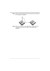
Motherboard Manual Step 3: Hold the CPU down firmly, and then close the lever toward direct B to the CPU_FAN1. Step 4: Put the CPU Fan on the CPU and buckle it. This completes the installation. 6 Connect the CPU FAN power cable to complete the installation.
Motherboard Manual Step 3: Hold the CPU down firmly, and then close the lever toward direct B to the CPU_FAN1. Step 4: Put the CPU Fan on the CPU and buckle it. This completes the installation. 6 Connect the CPU FAN power cable to complete the installation.
Setup Manual
Page 10
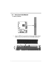
Memory Modules 1. Align a DIMM on the slot such that the notch on the DIMM matches the break on the Slot. 8 Unlock a DIMM slot by pressing the retaining clips outward. DDR3_A 1 DDR3_B 1 Motherboard Manual 2.3 INSTALLING SYSTEM MEMORY A.
Memory Modules 1. Align a DIMM on the slot such that the notch on the DIMM matches the break on the Slot. 8 Unlock a DIMM slot by pressing the retaining clips outward. DDR3_A 1 DDR3_B 1 Motherboard Manual 2.3 INSTALLING SYSTEM MEMORY A.
Setup Manual
Page 12
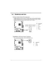
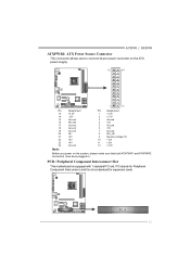
A55MH satisfies the SATA 2.0 spec and with 6 channels SATA interface. Motherboard Manual 2.4 CONNECTORS AND SLOTS SATA1~SATA6: Serial ATA Connectors A75MH/A55MH has a PCI to CPU power circuit. 14 23 Pin Assignment 1 +12V 2 +12V 3 Ground 4 Ground 10 A75MH satisfies the SATA 3.0 spec and with transfer rate of 3.0Gb/s. Pin Assignment 1 Ground SA TA4 SATA 5 SATA 6 2 TX+ SA TA3 S ATA2 SATA1 3 TX- 4 Ground 7 5 RX- 6 RX+ 4 7 Ground 1 ATXPWR2: ATX Power Source Connector This connector will provide +12V to SATA Controller with transfer rate of 6.0Gb/s;
A55MH satisfies the SATA 2.0 spec and with 6 channels SATA interface. Motherboard Manual 2.4 CONNECTORS AND SLOTS SATA1~SATA6: Serial ATA Connectors A75MH/A55MH has a PCI to CPU power circuit. 14 23 Pin Assignment 1 +12V 2 +12V 3 Ground 4 Ground 10 A75MH satisfies the SATA 3.0 spec and with transfer rate of 3.0Gb/s. Pin Assignment 1 Ground SA TA4 SATA 5 SATA 6 2 TX+ SA TA3 S ATA2 SATA1 3 TX- 4 Ground 7 5 RX- 6 RX+ 4 7 Ground 1 ATXPWR2: ATX Power Source Connector This connector will provide +12V to SATA Controller with transfer rate of 6.0Gb/s;
Setup Manual
Page 13
A75MH / A55MH ATXPWR1: ATX Power Source Connector This connector allows user to connect 24-pin power connector on the ATX power supply. 12 24 1 13 Pin ...: Before you power on the system, please make sure that both ATXPWR1 and ATXPWR2 connectors have been plugged-in. PCI1: Peripheral Component Interconnect Slot This motherboard is a bus standard for expansion cards. PCI stands for Peripheral Component Interconnect, and it is equipped with 1 standard PCI slot. PC I1 11
A75MH / A55MH ATXPWR1: ATX Power Source Connector This connector allows user to connect 24-pin power connector on the ATX power supply. 12 24 1 13 Pin ...: Before you power on the system, please make sure that both ATXPWR1 and ATXPWR2 connectors have been plugged-in. PCI1: Peripheral Component Interconnect Slot This motherboard is a bus standard for expansion cards. PCI stands for Peripheral Component Interconnect, and it is equipped with 1 standard PCI slot. PC I1 11
Setup Manual
Page 14
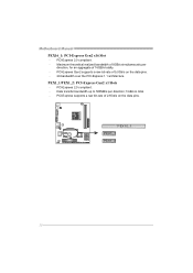
PCI-Express Gen2 supports a raw bit-rate of 2.5Gb/s on the data pins. - 2X bandwidth over the PCI-Express 1.1 architecture. Data transfer bandwidth up to 500MB/s per direction, for an aggregate of 8GB/s simultaneously per direction; 1GB/s in total. - Maximum theoretical realized bandwidth of 16GB/s totally. - PCI-Express supports a raw bit-rate of 5.0Gb/s on the data pins. PCI-Express 2.0 compliant. - Motherboard Manual PEX16_1: PCI-Express Gen2 x16 Slot - PCI-Express 2.0 compliant. - PEX1_1/PEX1_2: PCI-Express Gen2 x1 Slots - PEX16_1 PEX1_1 PEX1_2 12
PCI-Express Gen2 supports a raw bit-rate of 2.5Gb/s on the data pins. - 2X bandwidth over the PCI-Express 1.1 architecture. Data transfer bandwidth up to 500MB/s per direction, for an aggregate of 8GB/s simultaneously per direction; 1GB/s in total. - Maximum theoretical realized bandwidth of 16GB/s totally. - PCI-Express supports a raw bit-rate of 5.0Gb/s on the data pins. PCI-Express 2.0 compliant. - Motherboard Manual PEX16_1: PCI-Express Gen2 x16 Slot - PCI-Express 2.0 compliant. - PEX1_1/PEX1_2: PCI-Express Gen2 x1 Slots - PEX16_1 PEX1_1 PEX1_2 12
Setup Manual
Page 16
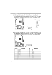
... Assignment 1 +5V (fused) 2 +5V (fused) 3 USB4 USB5 USB+ 6 USB+ 7 Ground 8 Ground 9 NC 10 Key 1 9 JFRONT_USB3_1: Header for USB 2.0 Ports at Front Panel (A75MH) This header allows user to connect additional USB cable on the PC front panel, and also can be connected with internal USB devices, like USB...Pin Assignment 11 D2+ 12 D2- 13 Ground 14 SSTX2+ 15 SSTX2- 16 Ground 17 SSRX2+ 18 SSRX2- 19 VBUS1 20 Key 14 Motherboard Manual F_USB1/F_USB2: Headers for USB 3.0 Ports at Front Panel This header allows user to connect additional USB cable on the PC front panel, ...
... Assignment 1 +5V (fused) 2 +5V (fused) 3 USB4 USB5 USB+ 6 USB+ 7 Ground 8 Ground 9 NC 10 Key 1 9 JFRONT_USB3_1: Header for USB 2.0 Ports at Front Panel (A75MH) This header allows user to connect additional USB cable on the PC front panel, and also can be connected with internal USB devices, like USB...Pin Assignment 11 D2+ 12 D2- 13 Ground 14 SSTX2+ 15 SSTX2- 16 Ground 17 SSRX2+ 18 SSRX2- 19 VBUS1 20 Key 14 Motherboard Manual F_USB1/F_USB2: Headers for USB 3.0 Ports at Front Panel This header allows user to connect additional USB cable on the PC front panel, ...
Setup Manual
Page 18
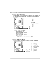
...and the CMOS data. Remove AC power line. 2. Set the jumper to "Pin 2-3 close ". 5. J_COM1: Serial Port Connector The motherboard has a Serial Port Connector for five seconds. 4. Set the jumper to "Pin 1-2 close ". 3. Load Optimal Defaults and save settings...detect 2 Received data 3 Transmitted data 4 Data terminal ready 5 Signal ground 6 Data set ready 7 Request to send 2 10 8 Clear to avoid damaging the motherboard. 3 1 Pin 1-2 Close: Normal Operation (default). 3 ※ Clear CMOS Procedures: 1 3 1 Pin 2-3 Close: Clear CMOS data. 1. Please carefully follow...
...and the CMOS data. Remove AC power line. 2. Set the jumper to "Pin 2-3 close ". 5. J_COM1: Serial Port Connector The motherboard has a Serial Port Connector for five seconds. 4. Set the jumper to "Pin 1-2 close ". 3. Load Optimal Defaults and save settings...detect 2 Received data 3 Transmitted data 4 Data terminal ready 5 Signal ground 6 Data set ready 7 Request to send 2 10 8 Clear to avoid damaging the motherboard. 3 1 Pin 1-2 Close: Normal Operation (default). 3 ※ Clear CMOS Procedures: 1 3 1 Pin 2-3 Close: Clear CMOS data. 1. Please carefully follow...
Setup Manual
Page 20
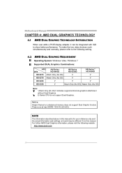
... your reference only and the actual information and settings on board may be integrated with IGD to the following website: http://www.amd.com 18 Motherboard Manual CHAPTER 4: AMD DUAL GRAPHICS TECHNOLOGY 4.1 AMD DUAL GRAPHICS TECHNOLOGY INTRODUCTION When user adds a PCIE display adapter, it can be different from this manual. For...
... your reference only and the actual information and settings on board may be integrated with IGD to the following website: http://www.amd.com 18 Motherboard Manual CHAPTER 4: AMD DUAL GRAPHICS TECHNOLOGY 4.1 AMD DUAL GRAPHICS TECHNOLOGY INTRODUCTION When user adds a PCIE display adapter, it can be different from this manual. For...
Setup Manual
Page 22
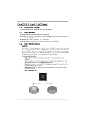
... for large files. If any fault tolerance. This technique reduces overall disk access time and offers high bandwidth. Block 1 Block 3 Block 5 20 Block 2 Block 4 Block 6 Motherboard Manual CHAPTER 5: RAID FUNCTIONS 5.1 OPERATING SYSTEM Supports Windows XP, Windows Vista, and Windows 7. 5.2 RAID ARRAYS RAID supports the following types of RAID arrays: RAID 0: RAID...
... for large files. If any fault tolerance. This technique reduces overall disk access time and offers high bandwidth. Block 1 Block 3 Block 5 20 Block 2 Block 4 Block 6 Motherboard Manual CHAPTER 5: RAID FUNCTIONS 5.1 OPERATING SYSTEM Supports Windows XP, Windows Vista, and Windows 7. 5.2 RAID ARRAYS RAID supports the following types of RAID arrays: RAID 0: RAID...
Setup Manual
Page 24
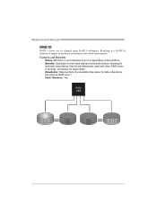
..., and allows for spare disks. Drawbacks: Requires twice the available disk space for data redundancy, the same as RAID level 1. Fault Tolerance: Yes. Motherboard Manual RAID 10: RAID 1 drives can be simultaneously used with other RAID levels in a RAID 10 solution for automatic redundancy. Features and Benefits Drives...
..., and allows for spare disks. Drawbacks: Requires twice the available disk space for data redundancy, the same as RAID level 1. Fault Tolerance: Yes. Motherboard Manual RAID 10: RAID 1 drives can be simultaneously used with other RAID levels in a RAID 10 solution for automatic redundancy. Features and Benefits Drives...
Setup Manual
Page 25
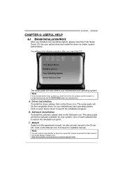
...Acrobat Reader software from the paperback manual, we also provide manual in the Driver CD. A. Click on the Driver icon. CHAPTER 6: USEFUL HELP A75MH / A55MH 6.1 DRIVER INSTALLATION NOTE After you installed your operating system, please insert the Fully Setup Driver CD into your optical drive and install the...the following window after you insert the CD The setup guide will need Acrobat Reader to locate and execute the file SETUP.EXE under your motherboard and operating system. Note: If this window didn't show up after you insert the Driver CD, please use file browser to open ...
...Acrobat Reader software from the paperback manual, we also provide manual in the Driver CD. A. Click on the Driver icon. CHAPTER 6: USEFUL HELP A75MH / A55MH 6.1 DRIVER INSTALLATION NOTE After you installed your operating system, please insert the Fully Setup Driver CD into your optical drive and install the...the following window after you insert the CD The setup guide will need Acrobat Reader to locate and execute the file SETUP.EXE under your motherboard and operating system. Note: If this window didn't show up after you insert the Driver CD, please use file browser to open ...
Setup Manual
Page 26
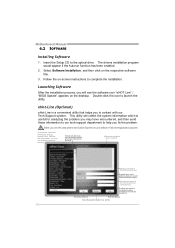
Motherboard Manual 6.2 SOFTWARE Installing Software 1. Select Software Installation, and then click on the desktop. eHot-Line (Optional) eHot-Line is useful for analyzing the problem you ...
Motherboard Manual 6.2 SOFTWARE Installing Software 1. Select Software Installation, and then click on the desktop. eHot-Line (Optional) eHot-Line is useful for analyzing the problem you ...
Setup Manual
Page 27
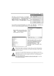
...tech support with any other e-mail application. Enter the file name and then click "Save". This information is also concluded in the sent mail. A75MH / A55MH If you will not share customer's data with other third parties, so please feel free to provide your default e-mail client application,... Not Send" to send the mail out. and then you will be saved to the following web http://www.biostar.com.tw/app/en-us/about/contact.php for your system information including motherboard/BIOS/CPU/video/ device/OS information. After filling up this information to enter file name.
...tech support with any other e-mail application. Enter the file name and then click "Save". This information is also concluded in the sent mail. A75MH / A55MH If you will not share customer's data with other third parties, so please feel free to provide your default e-mail client application,... Not Send" to send the mail out. and then you will be saved to the following web http://www.biostar.com.tw/app/en-us/about/contact.php for your system information including motherboard/BIOS/CPU/video/ device/OS information. After filling up this information to enter file name.
Setup Manual
Page 28
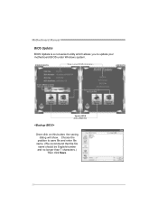
Choose the position to a .bin file Update BIOS with a BIOS file Once click on this button, the saving dialog will show. AWARD BIOS Show current BIOS information AMI BIOS Clear CMOS function (Only for AWARD BIOS) Save current BIOS to save file and enter file name. (We recommend that the file name should be English/number and no longer than 7 characters.) Then click Save. 26 Motherboard Manual BIOS Update BIOS Update is a convenient utility which allows you to update your motherboard BIOS under Windows system.
Choose the position to a .bin file Update BIOS with a BIOS file Once click on this button, the saving dialog will show. AWARD BIOS Show current BIOS information AMI BIOS Clear CMOS function (Only for AWARD BIOS) Save current BIOS to save file and enter file name. (We recommend that the file name should be English/number and no longer than 7 characters.) Then click Save. 26 Motherboard Manual BIOS Update BIOS Update is a convenient utility which allows you to update your motherboard BIOS under Windows system.

Setup Manual
Page 30
... avoid a damage of the CPU, and the system may not power on again. Or you can: 1. Power on the system again. 28 Motherboard Manual 6.3 EXTRA INFORMATION CPU Overheated If the system shutdown automatically after power on system for seconds. 2. When the CPU is rotated normally. 3.... In this case, please double check: 1. CPU fan is over heated, the motherboard will shutdown automatically to relief the CPU protection function. 1. Remove the power cord from power supply for seconds, that means the CPU protection function...
... avoid a damage of the CPU, and the system may not power on again. Or you can: 1. Power on the system again. 28 Motherboard Manual 6.3 EXTRA INFORMATION CPU Overheated If the system shutdown automatically after power on system for seconds. 2. When the CPU is rotated normally. 3.... In this case, please double check: 1. CPU fan is over heated, the motherboard will shutdown automatically to relief the CPU protection function. 1. Remove the power cord from power supply for seconds, that means the CPU protection function...
Setup Manual
Page 31
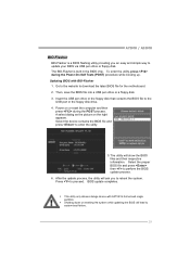
... Select the device contains the BIOS file and press to perform the BIOS update process. 6. Press to download the latest BIOS file for the motherboard. 2. Go to the website to proceed. z This utility only allows storage device with BIO-Flasher 1. After the update process, the utility ...will show the BIOS files and their respective information. Power on the right appears. A75MH / A55MH BIO-Flasher BIO-Flasher is built in the BIOS chip. To enter the utility, press during the POST process. The BIO-Flasher...
... Select the device contains the BIOS file and press to perform the BIOS update process. 6. Press to download the latest BIOS file for the motherboard. 2. Go to the website to proceed. z This utility only allows storage device with BIO-Flasher 1. After the update process, the utility ...will show the BIOS files and their respective information. Power on the right appears. A75MH / A55MH BIO-Flasher BIO-Flasher is built in the BIOS chip. To enter the utility, press during the POST process. The BIO-Flasher...

