Operation Manual
Page 1
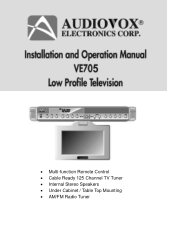
• Multi-function Remote Control • Cable Ready 125 Channel TV Tuner • Internal Stereo Speakers • Under Cabinet / Table Top Mounting • AM/FM Radio Tuner 0
• Multi-function Remote Control • Cable Ready 125 Channel TV Tuner • Internal Stereo Speakers • Under Cabinet / Table Top Mounting • AM/FM Radio Tuner 0
Operation Manual
Page 3
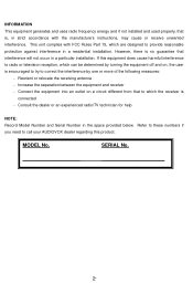
...will not occur in a residential installation. Reorient or relocate the receiving antenna - Refer to these numbers if you need to call your AUDIOVOX dealer regarding this equipment does cause harmful interference to radio or television reception, which can be determined by turning the equipment off and ... to correct the interference by one or more of the following measures: - SERIAL No. 2- Consult the dealer or an experienced radio/TV technician for help NOTE: Record Model Number and Serial Number in strict accordance with FCC Rules Part 15, which the receiver is connected ...
...will not occur in a residential installation. Reorient or relocate the receiving antenna - Refer to these numbers if you need to call your AUDIOVOX dealer regarding this equipment does cause harmful interference to radio or television reception, which can be determined by turning the equipment off and ... to correct the interference by one or more of the following measures: - SERIAL No. 2- Consult the dealer or an experienced radio/TV technician for help NOTE: Record Model Number and Serial Number in strict accordance with FCC Rules Part 15, which the receiver is connected ...
Operation Manual
Page 6
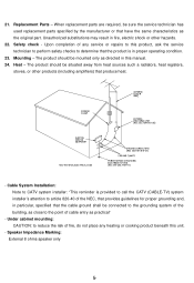
... technician to perform safety checks to the point of cable entry as close to determine that the product is provided to call the CATV (CABLE-TV) system installer's attention to article 820-40 of fire, do not place any service or repairs to this manual. 24.
... technician to perform safety checks to the point of cable entry as close to determine that the product is provided to call the CATV (CABLE-TV) system installer's attention to article 820-40 of fire, do not place any service or repairs to this manual. 24.

Operation Manual
Page 7
... Positioning the Screen 14 Setting the Time 14 Setting and Activating The Alarm 15 Deactivating Alarm 15 Setting the Alarm Tones 15 Setting the Cable TV Mode 15 Setting the Air TV Mode 16 Setting the Presets (For FM and AM or TV Modes 16 Technical Specifications 17 Troubleshooting Check List 18 6-
... Positioning the Screen 14 Setting the Time 14 Setting and Activating The Alarm 15 Deactivating Alarm 15 Setting the Alarm Tones 15 Setting the Cable TV Mode 15 Setting the Air TV Mode 16 Setting the Presets (For FM and AM or TV Modes 16 Technical Specifications 17 Troubleshooting Check List 18 6-
Operation Manual
Page 8
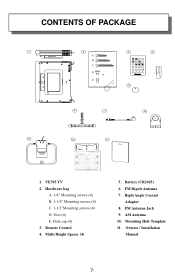
Remote Control 4. FM Antenna Jack 9. Hole cap (4) 3. Owners / Installation Manual 7 - Multi Height Spacer (4) 5. Battery (CR2025) 6. Right Angle Coaxial Adaptor 8. AM Antenna 10. Mounting Hole Template 11. FM Dipole Antenna 7. Foot (4) E. VE705 TV 2. Hardware bag A. 3/4" Mounting screws (4) B. 1-1/4" Mounting screws (4) C. 1-1/2"Mounting screws (4) D. CONTENTS OF PACKAGE PWR T EL TV VOL M U TE CH ENT CH VOL SEEK A /V F M /A M 1 2 3 ER ASE 4 5 6 AD D 7 8 9 0 1.
Remote Control 4. FM Antenna Jack 9. Hole cap (4) 3. Owners / Installation Manual 7 - Multi Height Spacer (4) 5. Battery (CR2025) 6. Right Angle Coaxial Adaptor 8. AM Antenna 10. Mounting Hole Template 11. FM Dipole Antenna 7. Foot (4) E. VE705 TV 2. Hardware bag A. 3/4" Mounting screws (4) B. 1-1/4" Mounting screws (4) C. 1-1/2"Mounting screws (4) D. CONTENTS OF PACKAGE PWR T EL TV VOL M U TE CH ENT CH VOL SEEK A /V F M /A M 1 2 3 ER ASE 4 5 6 AD D 7 8 9 0 1.
Operation Manual
Page 9
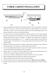
... it in the mounting hole. Place the screws selected through the VE705 and then through the spacers (if required from the bottom-up) 6) Connect your TV antenna or cable system to the electrical connection on the rear of the VE705. 7) Attach the FM Dipole Antenna and position the antenna for ...the best reception. 8) Attach the AM Antenna and position the antenna for the best reception. 9) Position the VE705 and mount it may be...
... it in the mounting hole. Place the screws selected through the VE705 and then through the spacers (if required from the bottom-up) 6) Connect your TV antenna or cable system to the electrical connection on the rear of the VE705. 7) Attach the FM Dipole Antenna and position the antenna for ...the best reception. 8) Attach the AM Antenna and position the antenna for the best reception. 9) Position the VE705 and mount it may be...

Operation Manual
Page 11
...WINDOW - BUTTON - Press these buttons to go to raise the volume. 15) VOLUME DOWN (W) BUTTON - Press this button to set the TIME, ALARM, TV Mode or Speaker Mode. 3) ADD BUTTON - Press this button to mute the audio (++++ will appear and blink on the unused port. BUTTON - FRONT ... to change the aspect ratio. 7) FM BUTTON - Press this button to the illustration above) into the unit. Selected Preset Channel "2" in the Radio or TV mode 11) P3 - 7) Insert the rubber pieces (#6) (Foot, Mounting Cap - Displays the channel/station number, time, and selected source. 19) REMOTE...
...WINDOW - BUTTON - Press these buttons to go to raise the volume. 15) VOLUME DOWN (W) BUTTON - Press this button to set the TIME, ALARM, TV Mode or Speaker Mode. 3) ADD BUTTON - Press this button to mute the audio (++++ will appear and blink on the unused port. BUTTON - FRONT ... to change the aspect ratio. 7) FM BUTTON - Press this button to the illustration above) into the unit. Selected Preset Channel "2" in the Radio or TV mode 11) P3 - 7) Insert the rubber pieces (#6) (Foot, Mounting Cap - Displays the channel/station number, time, and selected source. 19) REMOTE...

Operation Manual
Page 12
Connects to a 75-Ohm external coaxial antenna for the reception of FM broadcast signals. 3) AM ANTENNA - Allows the VE705 to be connected to a 75-ohm external coaxial antenna or cable TV system. 11- Allows the VE705 to be connected to an external antenna for the reception of AM broadcast signals. 4) TV ANTENNA (75 OHM ANTENNA CONNECTOR) -Allows the VE705 to be connected to AC power outlet 2) FM ANTENNA - hand held remote control unit. REAR PANEL CONNECTIONS 1 2 3 4 1) AC LINE CORD -
Connects to a 75-Ohm external coaxial antenna for the reception of FM broadcast signals. 3) AM ANTENNA - Allows the VE705 to be connected to a 75-ohm external coaxial antenna or cable TV system. 11- Allows the VE705 to be connected to an external antenna for the reception of AM broadcast signals. 4) TV ANTENNA (75 OHM ANTENNA CONNECTOR) -Allows the VE705 to be connected to AC power outlet 2) FM ANTENNA - hand held remote control unit. REAR PANEL CONNECTIONS 1 2 3 4 1) AC LINE CORD -
Operation Manual
Page 14
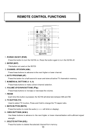
... 13- NUMERICAL BUTTONS (1~9, 0) Press these buttons to turn the VE705 off. 2. ENTER (ENT) This button not used on . AUTO PROGRAM (AP) Press this button to turn the VE705 on the VE705 3. TV BUTTON (TV) Used to select TV function, Press and Hold to make a direct channel selection. 6.... VOLUME UP/DOWN BUTTONS (TS) Press these buttons to change the TV aspect ratio. 9. DELETE BUTTON (DEL) Press this ...
... 13- NUMERICAL BUTTONS (1~9, 0) Press these buttons to turn the VE705 off. 2. ENTER (ENT) This button not used on . AUTO PROGRAM (AP) Press this button to turn the VE705 on the VE705 3. TV BUTTON (TV) Used to select TV function, Press and Hold to make a direct channel selection. 6.... VOLUME UP/DOWN BUTTONS (TS) Press these buttons to change the TV aspect ratio. 9. DELETE BUTTON (DEL) Press this ...

Operation Manual
Page 15
... mode and channel search mode is concluded. When set to normal broadcast reception of VHF and UHF channels, if you are performed with the VE705 turned off . When set to any commands. Pressing the PWR button on the unit or the remote will turn the unit off and pivot...limit. Please wait while the unit auto-programs before attempting to cable TV mode. NOTE: Most cable companies broadcast in use. The VE705 is reached. SETTING THE TIME NOTE: All settings (except setting the presets) are Cable TV subscriber, your new TV is first powered on or off . 1) Press the SET button and...
... mode and channel search mode is concluded. When set to normal broadcast reception of VHF and UHF channels, if you are performed with the VE705 turned off . When set to any commands. Pressing the PWR button on the unit or the remote will turn the unit off and pivot...limit. Please wait while the unit auto-programs before attempting to cable TV mode. NOTE: Most cable companies broadcast in use. The VE705 is reached. SETTING THE TIME NOTE: All settings (except setting the presets) are Cable TV subscriber, your new TV is first powered on or off . 1) Press the SET button and...
Operation Manual
Page 16
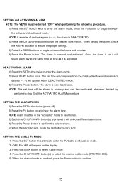
SETTING and ACTIVATING ALARM NOTE: The VE705 must be in the "Activated" mode to hear tones. 3) Each time CH UP/DOWN button(s) is pressed...the Display Window and a series of the ACTIVATING ALARM procedure. Once the alarm is reached, press the Power button to enter the TV/Cable configuration mode. 2) CABLE or AIR will sound each day at the same time as long as it off ). 2) Press... the P4 button once to set and activated. SETTING THE CABLE TV MODE 1) Press the SET button three times to confirm. 15- The set it will appear on the display. 3) Press...
SETTING and ACTIVATING ALARM NOTE: The VE705 must be in the "Activated" mode to hear tones. 3) Each time CH UP/DOWN button(s) is pressed...the Display Window and a series of the ACTIVATING ALARM procedure. Once the alarm is reached, press the Power button to enter the TV/Cable configuration mode. 2) CABLE or AIR will sound each day at the same time as long as it off ). 2) Press... the P4 button once to set and activated. SETTING THE CABLE TV MODE 1) Press the SET button three times to confirm. 15- The set it will appear on the display. 3) Press...

Operation Manual
Page 17
SETTING THE PRESETS (IN AM, FM OR TV MODES) 1) Tune the desired channel/station. 2) Press the SET button and the display flashes. 3) Press desired preset (P1, P2, P3 & P4) to confirm. SETTING THE AIR TV MODE 1) Press the SET button three times to enter the TV/Cable configuration mode. 2) Press the SEEK button to select the AIR mode. 3) Press the POWER button to confirm the selection. 16-
SETTING THE PRESETS (IN AM, FM OR TV MODES) 1) Tune the desired channel/station. 2) Press the SET button and the display flashes. 3) Press desired preset (P1, P2, P3 & P4) to confirm. SETTING THE AIR TV MODE 1) Press the SET button three times to enter the TV/Cable configuration mode. 2) Press the SEEK button to select the AIR mode. 3) Press the POWER button to confirm the selection. 16-
Operation Manual
Page 18
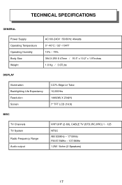
TECHNICAL SPECIFICATIONS GENERAL Power Supply Operating Temperature Operating Humidity Body Size Weight AC100-240V ~50/60Hz 40watts 0°~40°C / 32°~104°F 10% ~ 75% 394 X 259 X 47mm / 15.5" x 10.2" x 1.9"Inches 1.8 Kg / 3.97Lbs DISPLAY Illumination Backlighting Life Expectancy Resolution Screen CCFL Edge Lit Tube 10,000Hrs 1440(W) X 234(H) 7" TFT LCD (16:9) MISC TV Channels TV System Radio Frequency Range Audio output VHF/UHF (2-69), CABLE TV (STD,IRC,HRC) 1 - 125 NTSC AM 530KHz - 1710KHz FM 87.5MHz - 107.9MHz 1.2W / 8ohm (2 Speakers) 17-
TECHNICAL SPECIFICATIONS GENERAL Power Supply Operating Temperature Operating Humidity Body Size Weight AC100-240V ~50/60Hz 40watts 0°~40°C / 32°~104°F 10% ~ 75% 394 X 259 X 47mm / 15.5" x 10.2" x 1.9"Inches 1.8 Kg / 3.97Lbs DISPLAY Illumination Backlighting Life Expectancy Resolution Screen CCFL Edge Lit Tube 10,000Hrs 1440(W) X 234(H) 7" TFT LCD (16:9) MISC TV Channels TV System Radio Frequency Range Audio output VHF/UHF (2-69), CABLE TV (STD,IRC,HRC) 1 - 125 NTSC AM 530KHz - 1710KHz FM 87.5MHz - 107.9MHz 1.2W / 8ohm (2 Speakers) 17-


