User Guide
Page 13
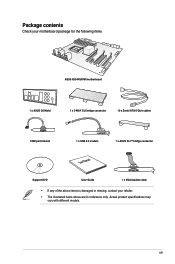
Package contents Check your motherboard package for the following items ASUS X99-WS/IPMI motherboard 1 x ASUS Q-Shield 1 x 3-WAY SLI bridge connector 10 x Serial ATA 6 Gb/s cables COM port bracket 1 x USB 2.0 module 1 x ASUS SLI™ bridge connector User Manual Support DVD User Guide 1 x VGA bracket cable • If any of the above items is damaged or missing, contact your retailer. • The illustrated items above are for reference only. xiii Actual product specifications may vary with different models.
Package contents Check your motherboard package for the following items ASUS X99-WS/IPMI motherboard 1 x ASUS Q-Shield 1 x 3-WAY SLI bridge connector 10 x Serial ATA 6 Gb/s cables COM port bracket 1 x USB 2.0 module 1 x ASUS SLI™ bridge connector User Manual Support DVD User Guide 1 x VGA bracket cable • If any of the above items is damaged or missing, contact your retailer. • The illustrated items above are for reference only. xiii Actual product specifications may vary with different models.

User Guide
Page 15
... speed. This helps enhance the performance of your system to catch up to meet the higher bandwidth requirements of PCIe 2.0. Chapter 1 ASUS X99-WS/IPMI 1-1 Quad-Channel DDR4 2133 MHz Support The motherboard supports the quad-channel DDR4 memory that supports the LGA2011-v3 socket for Intel®...; Core™ i7 processors This motherboard supports Intel® Core™ i7 processors in the LGA2011-v3 package. Intel® X99 Express Chipset Intel® X99 Express Chipset is dedicated only to six (6) USB 3.0 ports and ten (10) SATA 6 Gb/s ports. It provides great system...
... speed. This helps enhance the performance of your system to catch up to meet the higher bandwidth requirements of PCIe 2.0. Chapter 1 ASUS X99-WS/IPMI 1-1 Quad-Channel DDR4 2133 MHz Support The motherboard supports the quad-channel DDR4 memory that supports the LGA2011-v3 socket for Intel®...; Core™ i7 processors This motherboard supports Intel® Core™ i7 processors in the LGA2011-v3 package. Intel® X99 Express Chipset Intel® X99 Express Chipset is dedicated only to six (6) USB 3.0 ports and ten (10) SATA 6 Gb/s ports. It provides great system...

User Guide
Page 17
... install or remove any component, ensure that the ATX power supply is switched off or the power cord is detached from the power supply. Chapter 1 ASUS X99-WS/IPMI 1-3 1.2 Motherboard overview 1.2.1 Before you proceed Take note of the following precautions before you install motherboard components or change any motherboard settings. • Unplug the power...
... install or remove any component, ensure that the ATX power supply is switched off or the power cord is detached from the power supply. Chapter 1 ASUS X99-WS/IPMI 1-3 1.2 Motherboard overview 1.2.1 Before you proceed Take note of the following precautions before you install motherboard components or change any motherboard settings. • Unplug the power...

User Guide
Page 19
... 1-41 1-16 1-33 1-39 1-40 1-13 1-16 1-19 1-21 1-19 1-20 1-18 1-18 1-42 1-38 1-32 1-39 1-35 1-26 1-30 1-33 1-30 1-40 1-32 1-6 Chapter 1 ASUS X99-WS/IPMI 1-5 VGA controller setting jumper (VGA_SW1) 24. Q-Code LEDs 32. Digital audio connector (4-1 pin SPDIF_OUT) 35. M.2 Socket 3 connector 36. TPU switch 8. Reset button 9. EZ XMP switch...
... 1-41 1-16 1-33 1-39 1-40 1-13 1-16 1-19 1-21 1-19 1-20 1-18 1-18 1-42 1-38 1-32 1-39 1-35 1-26 1-30 1-33 1-30 1-40 1-32 1-6 Chapter 1 ASUS X99-WS/IPMI 1-5 VGA controller setting jumper (VGA_SW1) 24. Q-Code LEDs 32. Digital audio connector (4-1 pin SPDIF_OUT) 35. M.2 Socket 3 connector 36. TPU switch 8. Reset button 9. EZ XMP switch...

User Guide
Page 21
Recommended memory configurations Chapter 1 ASUS X99-WS/IPMI 1-7 1.2.4 System memory The motherboard comes with eight DDR 4 (Double Data Rate 4) Quad Inline Memory Modules (DIMM) slots. DO NOT install a DDR, DDR2, or DDR3 memory module to the DDR4 slot. A DDR4 module is notched differently from a DDR, DDR2, or DDR3 module.
Recommended memory configurations Chapter 1 ASUS X99-WS/IPMI 1-7 1.2.4 System memory The motherboard comes with eight DDR 4 (Double Data Rate 4) Quad Inline Memory Modules (DIMM) slots. DO NOT install a DDR, DDR2, or DDR3 memory module to the DDR4 slot. A DDR4 module is notched differently from a DDR, DDR2, or DDR3 module.

User Guide
Page 23
Failure to do so may not work if a 28-LANE CPU is installed. ASUS X99-WS/IPMI 1-9 1.2.5 Expansion slots Unplug the power cord before adding or removing expansion cards. Chapter 1 Slot No. 1 2 3 4 5 40-LANE PCIe 3.0/2.0 x16_1 slot PCIe 3.0/2.0 x16_2 slot PCIe 3.0/2.0 x16_3 slot PCIe 3.0/2.0 x16_4 slot PCIe 3.0/2.0 x16_5 slot Slot Description 28-LANE PCIe 3.0/2.0 x16_1 slot PCIe 3.0/2.0 x16_2 slot PCIe 3.0/2.0 x16_3 slot PCIe 3.0/2.0 x16_4 slot* PCIe 3.0/2.0 x16_5 slot *This slot may cause you physical injury and damage motherboard components.
Failure to do so may not work if a 28-LANE CPU is installed. ASUS X99-WS/IPMI 1-9 1.2.5 Expansion slots Unplug the power cord before adding or removing expansion cards. Chapter 1 Slot No. 1 2 3 4 5 40-LANE PCIe 3.0/2.0 x16_1 slot PCIe 3.0/2.0 x16_2 slot PCIe 3.0/2.0 x16_3 slot PCIe 3.0/2.0 x16_4 slot PCIe 3.0/2.0 x16_5 slot Slot Description 28-LANE PCIe 3.0/2.0 x16_1 slot PCIe 3.0/2.0 x16_2 slot PCIe 3.0/2.0 x16_3 slot PCIe 3.0/2.0 x16_4 slot* PCIe 3.0/2.0 x16_5 slot *This slot may cause you physical injury and damage motherboard components.

User Guide
Page 25
... Intel® EHCI 1 - - - - - shared - PCIe x16_2 shared - - - - - - - SMBUS Controller - - shared - - - - - - HD Audio - - - - - - AST2400 VGA shared - - - - - - - PCIe x16_3 PCIe x16_4 shared - - - - - - - Intel® xHCI - - - - - - - shared - - - - - Chapter 1 ASUS X99-WS/IPMI 1-11 Intel® EHCI 2 - - ASMedia Controller (1042AE) - - shared - - - - - - - shared - - - - - Intel® SATA Controller 2 shared - - - - - - - shared - -
... Intel® EHCI 1 - - - - - shared - PCIe x16_2 shared - - - - - - - SMBUS Controller - - shared - - - - - - HD Audio - - - - - - AST2400 VGA shared - - - - - - - PCIe x16_3 PCIe x16_4 shared - - - - - - - Intel® xHCI - - - - - - - shared - - - - - Chapter 1 ASUS X99-WS/IPMI 1-11 Intel® EHCI 2 - - ASMedia Controller (1042AE) - - shared - - - - - - - shared - - - - - Intel® SATA Controller 2 shared - - - - - - - shared - -

User Guide
Page 27
...the DIAG_DRAM LED increases, indicating different test processes. • Due to the latest BIOS version from www.asus.com after turning on the computer. If the installed DIMMs still fail to boot and load the BIOS ... not compatible with ones recommended in the Memory QVL (Qualified Vendors Lists) in this user manual or at www.asus.com. • If you download and update to memory tuning requirement, the system automatically reboots when each timing... system continues memory tuning after using the MemOK! 3. button lights continuously. MemOK! ASUS X99-WS/IPMI 1-13 Chapter 1
...the DIAG_DRAM LED increases, indicating different test processes. • Due to the latest BIOS version from www.asus.com after turning on the computer. If the installed DIMMs still fail to boot and load the BIOS ... not compatible with ones recommended in the Memory QVL (Qualified Vendors Lists) in this user manual or at www.asus.com. • If you download and update to memory tuning requirement, the system automatically reboots when each timing... system continues memory tuning after using the MemOK! 3. button lights continuously. MemOK! ASUS X99-WS/IPMI 1-13 Chapter 1

User Guide
Page 29
... enable the EPU switch. Enable this switch to section 1.2.8 Onboard LEDs for the exact location of the EPU LED. • If you have made. Chapter 1 ASUS X99-WS/IPMI 1-15
... enable the EPU switch. Enable this switch to section 1.2.8 Onboard LEDs for the exact location of the EPU LED. • If you have made. Chapter 1 ASUS X99-WS/IPMI 1-15

User Guide
Page 31
For the location of the EZ XMP LED, refer to enhance the DIMM's speed and performance. 8. EZ XMP switch Enable this switch to overclock the installed DIMMs, allowing you enable the EZ XMP switch. The EZ XMP LED (XLED1) lights up when you to section 1.2.8 Onboard LEDs. Chapter 1 ASUS X99-WS/IPMI 1-17
For the location of the EZ XMP LED, refer to enhance the DIMM's speed and performance. 8. EZ XMP switch Enable this switch to overclock the installed DIMMs, allowing you enable the EZ XMP switch. The EZ XMP LED (XLED1) lights up when you to section 1.2.8 Onboard LEDs. Chapter 1 ASUS X99-WS/IPMI 1-17

User Guide
Page 33
Chapter 1 ASUS X99-WS/IPMI 1-19 3. SMBUS connection setting jumper (3-pin TESLA_M_SW) This jumper allows you to BMC or PCH for PCIE 1, PCIE 3, and PCIE 5 SMBUS. 4. DDR4 Thermaltrip setting jumper (3-pin DIMMTRIP1) This jumper allows you to select the connection to enable or disable DDR4 DIMM thermal sensing event feature.
Chapter 1 ASUS X99-WS/IPMI 1-19 3. SMBUS connection setting jumper (3-pin TESLA_M_SW) This jumper allows you to BMC or PCH for PCIE 1, PCIE 3, and PCIE 5 SMBUS. 4. DDR4 Thermaltrip setting jumper (3-pin DIMMTRIP1) This jumper allows you to select the connection to enable or disable DDR4 DIMM thermal sensing event feature.

User Guide
Page 35
7. Chapter 1 ASUS X99-WS/IPMI 1-21 Power supply SMBus connector (PSUSMB1) This connector supplies power for low-speed system management communications. Set to pins 1-2 to enable o disable the Base Management Controller. Baseboard Management Controller jumper (3-pin BMC_EN1) This jumper allows you to activate the BMC feature. 8.
7. Chapter 1 ASUS X99-WS/IPMI 1-21 Power supply SMBus connector (PSUSMB1) This connector supplies power for low-speed system management communications. Set to pins 1-2 to enable o disable the Base Management Controller. Baseboard Management Controller jumper (3-pin BMC_EN1) This jumper allows you to activate the BMC feature. 8.

User Guide
Page 37
Chapter 1 ASUS X99-WS/IPMI 1-23 EZ XMP LED (XLED1) This LED lights up when the EPU switch is enabled. 4. 3. EPU LED (O2LED3) The EPU LED lights up when you enable the EZ XMP switch.
Chapter 1 ASUS X99-WS/IPMI 1-23 EZ XMP LED (XLED1) This LED lights up when the EPU switch is enabled. 4. 3. EPU LED (O2LED3) The EPU LED lights up when you enable the EZ XMP switch.

User Guide
Page 39
Power LED (+12V_PWR LED) The Power LED near the EATX12V1 connector lights up when the Baseboard Management Controller jumper is no power detected on the 8-pin EATX12V connector. 8. Baseboard Management Controller LED (BMC_LED1) The BMC LED lights up when you enable the ASUS Dr. Power switch and if there is set to enabled. Chapter 1 ASUS X99-WS/IPMI 1-25 7.
Power LED (+12V_PWR LED) The Power LED near the EATX12V1 connector lights up when the Baseboard Management Controller jumper is no power detected on the 8-pin EATX12V connector. 8. Baseboard Management Controller LED (BMC_LED1) The BMC LED lights up when you enable the ASUS Dr. Power switch and if there is set to enabled. Chapter 1 ASUS X99-WS/IPMI 1-25 7.

User Guide
Page 41
...) Recovery condition triggered by user (Forced recovery) Recovery process started Recovery firmware image is started DXE IPL is found (continued on the next page) Chapter 1 ASUS X99-WS/IPMI 1-27 E7 E8 E9 EA EB EC - Q-Code table Code 00 02 03 04 06 10 11 - 14 15 - 18 19 - 1C 2B - 2F 30...
...) Recovery condition triggered by user (Forced recovery) Recovery process started Recovery firmware image is started DXE IPL is found (continued on the next page) Chapter 1 ASUS X99-WS/IPMI 1-27 E7 E8 E9 EA EB EC - Q-Code table Code 00 02 03 04 06 10 11 - 14 15 - 18 19 - 1C 2B - 2F 30...

User Guide
Page 43
... from the S3 sleep state System is in PIC mode. Code AC AD AE AF B0 B1 B2 B3 B4 B5 B6 B7 B8- Chapter 1 ASUS X99-WS/IPMI 1-29 BF D0 D1 D2 D3 D4 D5 D6 D7 D8 D9 DA DB DC Description Reserved for ASL (see ASL Status Codes section below...
... from the S3 sleep state System is in PIC mode. Code AC AD AE AF B0 B1 B2 B3 B4 B5 B6 B7 B8- Chapter 1 ASUS X99-WS/IPMI 1-29 BF D0 D1 D2 D3 D4 D5 D6 D7 D8 D9 DA DB DC Description Reserved for ASL (see ASL Status Codes section below...

User Guide
Page 45
...; Due to chipset behavior, the SATA6G_78 and SATA6G_910 ports (black) do not support Intel® Rapid Storage Technology and RAID configuration. ASUS X99-WS/IPMI 1-31 Chapter 1 • These connectors are set the SATA Mode item in the motherboard support DVD. • The SATAEXPRESS_1 connector ...can create a RAID 0, 1, 5, and 10 configuration with the Intel® Rapid Storage Technology through the onboard Intel® X99 chipset. 3. Refer to section 3.6.3 PCH Storage Configuration for details. • Before creating a RAID set, refer to the manual bundled ...
...; Due to chipset behavior, the SATA6G_78 and SATA6G_910 ports (black) do not support Intel® Rapid Storage Technology and RAID configuration. ASUS X99-WS/IPMI 1-31 Chapter 1 • These connectors are set the SATA Mode item in the motherboard support DVD. • The SATAEXPRESS_1 connector ...can create a RAID 0, 1, 5, and 10 configuration with the Intel® Rapid Storage Technology through the onboard Intel® X99 chipset. 3. Refer to section 3.6.3 PCH Storage Configuration for details. • Before creating a RAID set, refer to the manual bundled ...

User Guide
Page 47
... to this connector, set the Front Panel Type item in the BIOS setup to and from devices rather than tripping the individual control lines. 6. Chapter 1 ASUS X99-WS/IPMI 1-33 This connector processes the messages to [HD] or [AC97]. 7. Connect one end of the motherboard's high-definition audio capability. • If you want to...
... to this connector, set the Front Panel Type item in the BIOS setup to and from devices rather than tripping the individual control lines. 6. Chapter 1 ASUS X99-WS/IPMI 1-33 This connector processes the messages to [HD] or [AC97]. 7. Connect one end of the motherboard's high-definition audio capability. • If you want to...

User Guide
Page 49
... (USB) to 48 Mb/s connection speed. 9. Connect the USB module cable to any of these connectors, then install the module to the USB connectors. Chapter 1 ASUS X99-WS/IPMI 1-35 DO NOT connect a 1394 cable to a slot opening at the back of the system chassis. The USB 2.0 module is purchased separately. US1112) These connectors...
... (USB) to 48 Mb/s connection speed. 9. Connect the USB module cable to any of these connectors, then install the module to the USB connectors. Chapter 1 ASUS X99-WS/IPMI 1-35 DO NOT connect a 1394 cable to a slot opening at the back of the system chassis. The USB 2.0 module is purchased separately. US1112) These connectors...

User Guide
Page 51
... 12 V Specification 2.0 (or later version) and provides a minimum power of 350 W. • DO NOT forget to the Recommended Power Supply Wattage Calculator at http://support.asus. ASUS X99-WS/IPMI 1-37 Chapter 1 11. com/PowerSupplyCalculator/PSCalculator.aspx?SLanguage=en-us for ATX power supply plugs. Find the proper orientation and push down firmly until the...
... 12 V Specification 2.0 (or later version) and provides a minimum power of 350 W. • DO NOT forget to the Recommended Power Supply Wattage Calculator at http://support.asus. ASUS X99-WS/IPMI 1-37 Chapter 1 11. com/PowerSupplyCalculator/PSCalculator.aspx?SLanguage=en-us for ATX power supply plugs. Find the proper orientation and push down firmly until the...


