User Guide
Page 2
...address gpl@asus.com, stating the product and describing the problem (please DO NOT send large attachments such as required under various Free Open Source Software licenses. or (2) the serial number of the product is dependent on the preferred carrier and the location where you may be distributed WITHOUT ANY WARRANTY and licensed under the Lesser General Public License Version...source code of their respective companies, and are included in any form or by ASUS; SPECIFICATIONS AND INFORMATION CONTAINED IN THIS MANUAL ARE FURNISHED FOR INFORMATIONAL USE ONLY, AND ARE SUBJECT TO CHANGE AT ...
...address gpl@asus.com, stating the product and describing the problem (please DO NOT send large attachments such as required under various Free Open Source Software licenses. or (2) the serial number of the product is dependent on the preferred carrier and the location where you may be distributed WITHOUT ANY WARRANTY and licensed under the Lesser General Public License Version...source code of their respective companies, and are included in any form or by ASUS; SPECIFICATIONS AND INFORMATION CONTAINED IN THIS MANUAL ARE FURNISHED FOR INFORMATIONAL USE ONLY, AND ARE SUBJECT TO CHANGE AT ...
User Guide
Page 5
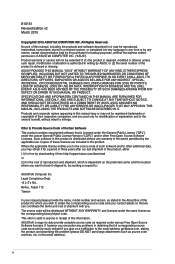
... 4.4 ASUS Utilities 4-4 4.4.1 Ai Charger 4-6 4.4.2 USB Charger 4-7 4.4.3 ASUS Dr. Power Utility 4-8 4.5 Audio configurations 4-10 Chapter 5: RAID support 5.1 RAID configurations 5-1 5.1.1 RAID definitions 5-1 5.1.2 Installing Serial ATA hard disks 5-2 5.1.3 Setting the RAID item in BIOS 5-2 5.1.4 Intel® Rapid Storage Technology Option ROM utility 5-3 5.2 Creating a RAID driver disk 5-7 5.2.1 Creating a RAID driver disk without entering the OS 5-7 5.2.2 Creating a RAID driver disk in Windows 5-8 5.2.3 Installing the RAID driver during Windows® OS installation...
... 4.4 ASUS Utilities 4-4 4.4.1 Ai Charger 4-6 4.4.2 USB Charger 4-7 4.4.3 ASUS Dr. Power Utility 4-8 4.5 Audio configurations 4-10 Chapter 5: RAID support 5.1 RAID configurations 5-1 5.1.1 RAID definitions 5-1 5.1.2 Installing Serial ATA hard disks 5-2 5.1.3 Setting the RAID item in BIOS 5-2 5.1.4 Intel® Rapid Storage Technology Option ROM utility 5-3 5.2 Creating a RAID driver disk 5-7 5.2.1 Creating a RAID driver disk without entering the OS 5-7 5.2.2 Creating a RAID driver disk in Windows 5-8 5.2.3 Installing the RAID driver during Windows® OS installation...

User Guide
Page 15
... with the speed of PCIe 2.0. It provides great system performance, quad-channel DDR4 memory slots and PCI Express 2.0/3.0 expansion slots. This helps enhance the performance of your system to catch up with up to two SATA drives of 3D graphics, multimedia and Internet applications. It natively supports up to six (6) USB 3.0 ports and ten (10) SATA 6 Gb/s ports. Chapter 1 ASUS X99-WS/IPMI 1-1 M.2 Support* This motherboard features the M.2 slot, which increases...
... with the speed of PCIe 2.0. It provides great system performance, quad-channel DDR4 memory slots and PCI Express 2.0/3.0 expansion slots. This helps enhance the performance of your system to catch up with up to two SATA drives of 3D graphics, multimedia and Internet applications. It natively supports up to six (6) USB 3.0 ports and ten (10) SATA 6 Gb/s ports. Chapter 1 ASUS X99-WS/IPMI 1-1 M.2 Support* This motherboard features the M.2 slot, which increases...

User Guide
Page 19
... 1-6 Chapter 1 ASUS X99-WS/IPMI 1-5 Auxiliary panel connector (20-2 pin AUX_PANEL1) 27. Serial port connector (10-1 pin COM1) 33. VGA connector (VGA_HDR1) 37. DDR4 DIMM slots 2. MemOK! CPU Over Voltage jumper (3-pin CPU_OV) 26. TPM connector (20-1 pin TPM) 30. M.2 Socket 3 connector 36. PMBus 1.2 PSU select jumper (3-pin SMART_PSU1) 4. TPU switch 8. EZ XMP switch 11. Q-Code LEDs 32. CPU, CPU optional, auxiliary, and chassis fan connectors (4-pin CPU_FAN1-2, 4-pin REAR_FAN1, 4-pin FRNT_FAN1-3, 4-pin AUX_FANSENSE) 6. Dr. Power switch (DR_POWER) 20...
... 1-6 Chapter 1 ASUS X99-WS/IPMI 1-5 Auxiliary panel connector (20-2 pin AUX_PANEL1) 27. Serial port connector (10-1 pin COM1) 33. VGA connector (VGA_HDR1) 37. DDR4 DIMM slots 2. MemOK! CPU Over Voltage jumper (3-pin CPU_OV) 26. TPM connector (20-1 pin TPM) 30. M.2 Socket 3 connector 36. PMBus 1.2 PSU select jumper (3-pin SMART_PSU1) 4. TPU switch 8. EZ XMP switch 11. Q-Code LEDs 32. CPU, CPU optional, auxiliary, and chassis fan connectors (4-pin CPU_FAN1-2, 4-pin REAR_FAN1, 4-pin FRNT_FAN1-3, 4-pin AUX_FANSENSE) 6. Dr. Power switch (DR_POWER) 20...

User Guide
Page 21
1.2.4 System memory The motherboard comes with eight DDR 4 (Double Data Rate 4) Quad Inline Memory Modules (DIMM) slots. A DDR4 module is notched differently from a DDR, DDR2, or DDR3 module. DO NOT install a DDR, DDR2, or DDR3 memory module to the DDR4 slot. Recommended memory configurations Chapter 1 ASUS X99-WS/IPMI 1-7
1.2.4 System memory The motherboard comes with eight DDR 4 (Double Data Rate 4) Quad Inline Memory Modules (DIMM) slots. A DDR4 module is notched differently from a DDR, DDR2, or DDR3 module. DO NOT install a DDR, DDR2, or DDR3 memory module to the DDR4 slot. Recommended memory configurations Chapter 1 ASUS X99-WS/IPMI 1-7

User Guide
Page 22
...; CPU spec, DIMM voltage below 1.65 V is recommended to protect the CPU. • Due to the Microsoft® support site at http://support.microsoft. settings in Channel A, Channel B, Channel C, and Channel D. b) Install a 64-bit Windows® OS when you install 4GB or more memory on the motherboard. com/kb/929605/en-us. • The default memory operation frequency is dependent on the CPU's capabilities and other installed devices. • Always install...
...; CPU spec, DIMM voltage below 1.65 V is recommended to protect the CPU. • Due to the Microsoft® support site at http://support.microsoft. settings in Channel A, Channel B, Channel C, and Channel D. b) Install a 64-bit Windows® OS when you install 4GB or more memory on the motherboard. com/kb/929605/en-us. • The default memory operation frequency is dependent on the CPU's capabilities and other installed devices. • Always install...

User Guide
Page 27
... and tests failsafe memory settings. button until the DIAG_DRAM LED starts blinking to begin automatic memory compatibility tuning for successful boot. • Refer to section 1.2.8 Onboard LEDs for about 30 seconds for the system to boot and load the BIOS default settings. button to test one set of failsafe settings. 3. MemOK! Replace the DIMMs with the motherboard may cause system boot failure, and the DIAG_DRAM LED near the MemOK! ASUS X99-WS/IPMI 1-13 Chapter 1 button Installing DIMMs that you turn off...
... and tests failsafe memory settings. button until the DIAG_DRAM LED starts blinking to begin automatic memory compatibility tuning for successful boot. • Refer to section 1.2.8 Onboard LEDs for about 30 seconds for the system to boot and load the BIOS default settings. button to test one set of failsafe settings. 3. MemOK! Replace the DIMMs with the motherboard may cause system boot failure, and the DIAG_DRAM LED near the MemOK! ASUS X99-WS/IPMI 1-13 Chapter 1 button Installing DIMMs that you turn off...

User Guide
Page 42
... Boot Device Selection (BDS) phase is started Driver connecting is started PCI Bus initialization is started PCI Bus Hot Plug Controller Initialization PCI Bus Enumeration PCI Bus Request Resources PCI Bus Assign Resources Console Output devices connect Console input devices connect Super IO Initialization USB initialization is started USB Reset USB Detect USB Enable Reserved for future AMI codes IDE initialization is started IDE Reset IDE Detect IDE Enable SCSI initialization is started SCSI Reset SCSI Detect SCSI Enable Setup Verifying Password Start of Setup Reserved for ASL (see ASL Status...
... Boot Device Selection (BDS) phase is started Driver connecting is started PCI Bus initialization is started PCI Bus Hot Plug Controller Initialization PCI Bus Enumeration PCI Bus Request Resources PCI Bus Assign Resources Console Output devices connect Console input devices connect Super IO Initialization USB initialization is started USB Reset USB Detect USB Enable Reserved for future AMI codes IDE initialization is started IDE Reset IDE Detect IDE Enable SCSI initialization is started SCSI Reset SCSI Detect SCSI Enable Setup Verifying Password Start of Setup Reserved for ASL (see ASL Status...

User Guide
Page 43
... ASL Status Codes section below) Ready To Boot event Legacy Boot event Exit Boot Services event Runtime Set Virtual Address MAP Begin Runtime Set Virtual Address MAP End Legacy Option ROM Initialization System Reset USB hot plug PCI bus hot plug Clean-up of NVRAM Configuration Reset (reset of NVRAM settings) Reserved for future AMI codes CPU initialization error System Agent initialization error PCH initialization error Some of Resources No Space for Legacy Option ROM No Console Output Devices are found Invalid password Error loading Boot Option (LoadImage returned error) Boot...
... ASL Status Codes section below) Ready To Boot event Legacy Boot event Exit Boot Services event Runtime Set Virtual Address MAP Begin Runtime Set Virtual Address MAP End Legacy Option ROM Initialization System Reset USB hot plug PCI bus hot plug Clean-up of NVRAM Configuration Reset (reset of NVRAM settings) Reserved for future AMI codes CPU initialization error System Agent initialization error PCH initialization error Some of Resources No Space for Legacy Option ROM No Console Output Devices are found Invalid password Error loading Boot Option (LoadImage returned error) Boot...

User Guide
Page 45
... and SATA6G_910 ports (black) do not support Intel® Rapid Storage Technology and RAID configuration. Intel® X99 Serial ATA 6 Gb/s connectors (7-pin SATA6G_12, SATA6G_34, SATA6G_56/SATAEXPRESS_1) These connectors connect to [AHCI Mode] by default. If you can support one SATA Express device or two SATA devices. • Due to [RAID Mode]. Refer to section 3.6.3 PCH Storage Configuration for details. • Before creating a RAID set to Serial ATA 6 Gb/s hard disk drives via Serial ATA 6 Gb/s signal cables. ASUS X99-WS/IPMI 1-31...
... and SATA6G_910 ports (black) do not support Intel® Rapid Storage Technology and RAID configuration. Intel® X99 Serial ATA 6 Gb/s connectors (7-pin SATA6G_12, SATA6G_34, SATA6G_56/SATAEXPRESS_1) These connectors connect to [AHCI Mode] by default. If you can support one SATA Express device or two SATA devices. • Due to [RAID Mode]. Refer to section 3.6.3 PCH Storage Configuration for details. • Before creating a RAID set to Serial ATA 6 Gb/s hard disk drives via Serial ATA 6 Gb/s signal cables. ASUS X99-WS/IPMI 1-31...
User Guide
Page 48
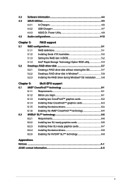
... rear panel ports. The USB 3.0 module is purchased separately. • Ensure to install the related driver to connect a USB 3.0 module for USB-chargeable devices, optimized power efficiency, and backward compatibility with USB 2.0. With an installed USB 3.0 module, you to fully use the USB 3.0 ports under Windows® 7. • The plugged USB 3.0 device may run on xHCI or EHCI mode depending on the operating system's setting. • These USB 3.0 ports support native UASP transfer standard in Windows® 8 / Windows® 8.1 and Turbo Mode when using USB...
... rear panel ports. The USB 3.0 module is purchased separately. • Ensure to install the related driver to connect a USB 3.0 module for USB-chargeable devices, optimized power efficiency, and backward compatibility with USB 2.0. With an installed USB 3.0 module, you to fully use the USB 3.0 ports under Windows® 7. • The plugged USB 3.0 device may run on xHCI or EHCI mode depending on the operating system's setting. • These USB 3.0 ports support native UASP transfer standard in Windows® 8 / Windows® 8.1 and Turbo Mode when using USB...

User Guide
Page 67
... Flashback LED blinks three times, indicating that supports USB BIOS Flashback. 3. Refer to section 2.4.1 Rear I /O shield) then press the USB BIOS Flashback button for five seconds and turns into a solid light, this scenario happens, please restart the system to as USB storage device. Chapter 2 USB BIOS Flashback port BIOS Flashback button 5. In case of the USB storage device and filename/file format error. 2.2 BIOS update utility USB BIOS Flashback USB BIOS Flashback allows you to use USB BIOS Flashback: 1. Simply insert a USB storage device to boot up...
... Flashback LED blinks three times, indicating that supports USB BIOS Flashback. 3. Refer to section 2.4.1 Rear I /O shield) then press the USB BIOS Flashback button for five seconds and turns into a solid light, this scenario happens, please restart the system to as USB storage device. Chapter 2 USB BIOS Flashback port BIOS Flashback button 5. In case of the USB storage device and filename/file format error. 2.2 BIOS update utility USB BIOS Flashback USB BIOS Flashback allows you to use USB BIOS Flashback: 1. Simply insert a USB storage device to boot up...

User Guide
Page 75
... the motherboard CMOS. The term "BIOS" in this motherboard. We strongly recommend that requires further BIOS settings or update. In normal circumstances, the default BIOS settings apply to most conditions to instability or boot failure. You can easily navigate the new UEFI BIOS with the same smoothness as storage device configuration, overclocking settings, advanced power management, and boot device configuration that goes beyond the traditional keyboardonly BIOS controls to enable a more flexible and convenient mouse input. Chapter 3 ASUS X99-WS/IPMI 3-1 BIOS...
... the motherboard CMOS. The term "BIOS" in this motherboard. We strongly recommend that requires further BIOS settings or update. In normal circumstances, the default BIOS settings apply to most conditions to instability or boot failure. You can easily navigate the new UEFI BIOS with the same smoothness as storage device configuration, overclocking settings, advanced power management, and boot device configuration that goes beyond the traditional keyboardonly BIOS controls to enable a more flexible and convenient mouse input. Chapter 3 ASUS X99-WS/IPMI 3-1 BIOS...

User Guide
Page 131
... to enable/disable the Serial Mux Configuration ASUS X99-WS/IPMI 3-57 Chapter 3 Configuration options: [Do Nothing] [Reset] [Power Down] Serial Mux [Disabled] This item allows you to configure the duration of the OS Boot Watchdof timer. Configuration options: [Disabled] [Enabled] The following items appear only when you to change its settings. 3.11 Server Management menu The Server Management menu displays the server management status and allows you set the Launch CSM to [Enabled]. OS Watchdog Timer [Disabled] This item allows you to start a BIOS...
... to enable/disable the Serial Mux Configuration ASUS X99-WS/IPMI 3-57 Chapter 3 Configuration options: [Do Nothing] [Reset] [Power Down] Serial Mux [Disabled] This item allows you to configure the duration of the OS Boot Watchdof timer. Configuration options: [Disabled] [Enabled] The following items appear only when you to change its settings. 3.11 Server Management menu The Server Management menu displays the server management status and allows you set the Launch CSM to [Enabled]. OS Watchdog Timer [Disabled] This item allows you to start a BIOS...
User Guide
Page 135
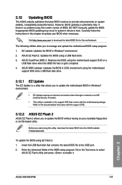
... Mode of BIOS, DO NOT manually update the BIOS. If there is available in Windows® environment. • EZ Update requires an Internet connection either through a network or an ISP (Internet Service Provider). • This utility is no problem using this motherboard. ASUS CrashFree BIOS 3: Restores the BIOS using the motherboard support DVD and a USB flash disk drive. 3.12.1 EZ Update The EZ Update is potentially risky. ASUS BIOS Updater: Updates the BIOS in Windows® environment. 2. Chapter 3 ASUS X99-WS/IPMI 3-61 Visit http://www.asus.com to download...
... Mode of BIOS, DO NOT manually update the BIOS. If there is available in Windows® environment. • EZ Update requires an Internet connection either through a network or an ISP (Internet Service Provider). • This utility is no problem using this motherboard. ASUS CrashFree BIOS 3: Restores the BIOS using the motherboard support DVD and a USB flash disk drive. 3.12.1 EZ Update The EZ Update is potentially risky. ASUS BIOS Updater: Updates the BIOS in Windows® environment. 2. Chapter 3 ASUS X99-WS/IPMI 3-61 Visit http://www.asus.com to download...
User Guide
Page 142
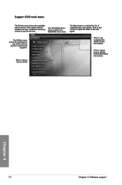
... Utilities menu shows the applications and other software that the motherboard supports. Click or tap an icon to use the devices. The Manual menu contains the list of the user guide. Install the necessary drivers to display DVD/motherboard information Chapter 4 4-2 Chapter 4: Software support Click or tap an item to display the ASUS contact information. Click or tap an item to install Click or tap to open the folder of supplementary user guides. The AHCI/RAID Driver menu...
... Utilities menu shows the applications and other software that the motherboard supports. Click or tap an icon to use the devices. The Manual menu contains the list of the user guide. Install the necessary drivers to display DVD/motherboard information Chapter 4 4-2 Chapter 4: Software support Click or tap an item to display the ASUS contact information. Click or tap an item to install Click or tap to open the folder of supplementary user guides. The AHCI/RAID Driver menu...

User Guide
Page 151
... identical hard disk drives is best suited for this setup. If you want to install a Windows® operating system to a hard disk drive included in a RAID set, you get all applications to read and write data in the other business systems. Use a minimum of both data and parity information across three or more hard disk drives. Use of the same size or larger than the existing drive. Chapter 5 X99-WS/IPMI 5-1 Two hard disks perform...
... identical hard disk drives is best suited for this setup. If you want to install a Windows® operating system to a hard disk drive included in a RAID set, you get all applications to read and write data in the other business systems. Use a minimum of both data and parity information across three or more hard disk drives. Use of the same size or larger than the existing drive. Chapter 5 X99-WS/IPMI 5-1 Two hard disks perform...
User Guide
Page 152
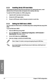
... POST. 2. Refer to RAID mode, all SATA ports run at RAID mode together. Chapter 5 5-2 Chapter 5: RAID configurations Go to [RAID Mode]. 4. Install the SATA hard disks into the drive bays. 2. Set the SATA Mode item to the Advanced menu > PCH Storage Configuration > SATA Controller 1 Mode Selection, then press . 3. Connect a SATA power cable to chipset limitation, when SATA ports are set the RAID item in the BIOS Setup before creating RAID sets using SATA HDDs. 5.1.2 Installing Serial ATA hard disks The motherboard supports Serial ATA hard disk drives. To install the SATA hard...
... POST. 2. Refer to RAID mode, all SATA ports run at RAID mode together. Chapter 5 5-2 Chapter 5: RAID configurations Go to [RAID Mode]. 4. Install the SATA hard disks into the drive bays. 2. Set the SATA Mode item to the Advanced menu > PCH Storage Configuration > SATA Controller 1 Mode Selection, then press . 3. Connect a SATA power cable to chipset limitation, when SATA ports are set the RAID item in the BIOS Setup before creating RAID sets using SATA HDDs. 5.1.2 Installing Serial ATA hard disks The motherboard supports Serial ATA hard disk drives. To install the SATA hard...

User Guide
Page 153
... menu options. Physical Devices: Port Device Model 0 ST3160812AS 1 ST3160812AS 2 ST3160812AS 3 ST3160812AS Serial # 9LS0HJA4 9LS0F4HL 3LS0JYL8 9LS0BJ5H Size 149.0GB 149.0GB 149.0GB 149.0GB Type/Status(Vol ID) Non-RAID Disk Non-RAID Disk Non-RAID Disk Non-RAID Disk The navigation keys at the bottom of the screen allow you to display the utility main menu. The RAID BIOS setup screens shown in this section are for RAID configuration. RAID Volumes: None defined. Chapter 5 X99-WS/IPMI...
... menu options. Physical Devices: Port Device Model 0 ST3160812AS 1 ST3160812AS 2 ST3160812AS 3 ST3160812AS Serial # 9LS0HJA4 9LS0F4HL 3LS0JYL8 9LS0BJ5H Size 149.0GB 149.0GB 149.0GB 149.0GB Type/Status(Vol ID) Non-RAID Disk Non-RAID Disk Non-RAID Disk Non-RAID Disk The navigation keys at the bottom of the screen allow you to display the utility main menu. The RAID BIOS setup screens shown in this section are for RAID configuration. RAID Volumes: None defined. Chapter 5 X99-WS/IPMI...
User Guide
Page 158
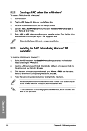
... to use another computer to copy the RAID driver from a USB flash drive, you 've inserted, go to the root path of the selected folder to Drivers > RAID, and then select the RAID driver for your optical drive. Insert the USB flash drive with RAID driver into the USB port or the support DVD into the optical drive. 4. To set up a Windows® UEFI operating system under RAID mode, ensure to complete the installation. Chapter 5 5-8 Chapter 5: RAID configurations 5.2.2 Creating a RAID driver disk in Windows...
... to use another computer to copy the RAID driver from a USB flash drive, you 've inserted, go to the root path of the selected folder to Drivers > RAID, and then select the RAID driver for your optical drive. Insert the USB flash drive with RAID driver into the USB port or the support DVD into the optical drive. 4. To set up a Windows® UEFI operating system under RAID mode, ensure to complete the installation. Chapter 5 5-8 Chapter 5: RAID configurations 5.2.2 Creating a RAID driver disk in Windows...


