
User Guide
Page 1
Motherboard X99-WS/ IPMI
Motherboard X99-WS/ IPMI

User Guide
Page 3
Contents Safety information...vi About this guide...vii X99-WS/IPMI specifications summary ix Package contents...xiii Installation tools and components xiv Chapter 1: Product Introduction 1.1 Special features 1-1 1.1.1 Product highlights 1-1 1.1.2 Other special features 1-2 1.2 Motherboard overview 1-3 1.2.1 Before you ...
Contents Safety information...vi About this guide...vii X99-WS/IPMI specifications summary ix Package contents...xiii Installation tools and components xiv Chapter 1: Product Introduction 1.1 Special features 1-1 1.1.1 Product highlights 1-1 1.1.2 Other special features 1-2 1.2 Motherboard overview 1-3 1.2.1 Before you ...

User Guide
Page 9
...22nm CPU Supports Intel® Turbo Boost Technology 2.0* * The Intel® Turbo Boost Technology 2.0 support depends on the next page) ix X99-WS/IPMI specifications summary CPU Chipset Memory Expansion slots Multi-GPU support Storage LAN Audio LGA2011-v3 socket for left and right track, ensuring both sound ...on the CPU types. Supports AMD® Quad-GPU CrossFireX™ Technology Supports NVIDIA® 3-Way SLI™ Technology* * Supports up to www.asus.com for the memory QVL (Qualified Vendors Lists). 40-LANE CPU 5 x PCI Express 3.0/2.0 x16 slots (single at x16, dual at x16/x16, ...
...22nm CPU Supports Intel® Turbo Boost Technology 2.0* * The Intel® Turbo Boost Technology 2.0 support depends on the next page) ix X99-WS/IPMI specifications summary CPU Chipset Memory Expansion slots Multi-GPU support Storage LAN Audio LGA2011-v3 socket for left and right track, ensuring both sound ...on the CPU types. Supports AMD® Quad-GPU CrossFireX™ Technology Supports NVIDIA® 3-Way SLI™ Technology* * Supports up to www.asus.com for the memory QVL (Qualified Vendors Lists). 40-LANE CPU 5 x PCI Express 3.0/2.0 x16 slots (single at x16, dual at x16/x16, ...

User Guide
Page 10
Optical S/PDIF out ports at rear I/O Intel® X99 Express Chipset - 6 x USB 3.0/2.0 (4 ports at front panel, 2 ports at rear panel) - 6 x USB 2.0/1.1 ports (4 ports at mid-board, 2 ports at back panel) ASMedia® USB 3.0 controllers ...High quality 109 dB SNR stereo playback output (Line-out at rear panel (blue) High Performance DIGI+ Power Control CPU Power - retasking (MIC) - X99-WS/IPMI specifications summary Audio USB ASUS Exclusive Features - DTS UltraPC II - EPU, EPU switch UEFI BIOS - Audio amplifier to 10 Gb/s data transfer speeds for headphone and speakers - ...
Optical S/PDIF out ports at rear I/O Intel® X99 Express Chipset - 6 x USB 3.0/2.0 (4 ports at front panel, 2 ports at rear panel) - 6 x USB 2.0/1.1 ports (4 ports at mid-board, 2 ports at back panel) ASMedia® USB 3.0 controllers ...High quality 109 dB SNR stereo playback output (Line-out at rear panel (blue) High Performance DIGI+ Power Control CPU Power - retasking (MIC) - X99-WS/IPMI specifications summary Audio USB ASUS Exclusive Features - DTS UltraPC II - EPU, EPU switch UEFI BIOS - Audio amplifier to 10 Gb/s data transfer speeds for headphone and speakers - ...

User Guide
Page 11
... 2 Q-Design - X99-WS/IPMI specifications summary ASUS Exclusive Features Rear Panel I/O Ports ASUS Special Features Worksation Exclusive Internal I /O jacks Special features: USB Charger+ Ai Charger+ Disk Unlocker MemOK! Monitor your PC status with auto detection support 1 x 4-pin CPU OPT Fan connector (continued on the next page) xi ASUS O.C. ASUS CrashFree BIOS 3 - featuring friendly graphics user interface - ASUS Q-LED...
... 2 Q-Design - X99-WS/IPMI specifications summary ASUS Exclusive Features Rear Panel I/O Ports ASUS Special Features Worksation Exclusive Internal I /O jacks Special features: USB Charger+ Ai Charger+ Disk Unlocker MemOK! Monitor your PC status with auto detection support 1 x 4-pin CPU OPT Fan connector (continued on the next page) xi ASUS O.C. ASUS CrashFree BIOS 3 - featuring friendly graphics user interface - ASUS Q-LED...

User Guide
Page 12
X99-WS/IPMI specifications summary Internal I/O Connectors BIOS features Manageability Support DVD Form Factors 4... headers 128 Mb Flash ROM, UEFI AMI BIOS, PnP, DMI 2.7, WfM 2.0, SM BIOS 2.7, ACPI 5.0, Multi-language BIOS, ASUS EZ Flash 2, CrashFree BIOS 3, F11 EZ Tuning Wizard, F3 My Favorites, Quick Note, Last Modified Log, F12 PrintScreen function, F3 ...Shortcut function, and ASUS DRAM SPD (Serial Presence Detect) memory information WfM 2.0, DMI 2.7, WOL by PME, PXE Drivers Anti-virus software...
X99-WS/IPMI specifications summary Internal I/O Connectors BIOS features Manageability Support DVD Form Factors 4... headers 128 Mb Flash ROM, UEFI AMI BIOS, PnP, DMI 2.7, WfM 2.0, SM BIOS 2.7, ACPI 5.0, Multi-language BIOS, ASUS EZ Flash 2, CrashFree BIOS 3, F11 EZ Tuning Wizard, F3 My Favorites, Quick Note, Last Modified Log, F12 PrintScreen function, F3 ...Shortcut function, and ASUS DRAM SPD (Serial Presence Detect) memory information WfM 2.0, DMI 2.7, WOL by PME, PXE Drivers Anti-virus software...
User Guide
Page 13
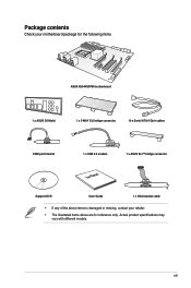
xiii Package contents Check your motherboard package for the following items ASUS X99-WS/IPMI motherboard 1 x ASUS Q-Shield 1 x 3-WAY SLI bridge connector 10 x Serial ATA 6 Gb/s cables COM port bracket 1 x USB 2.0 module 1 x ASUS SLI™ bridge connector User Manual Support DVD User Guide 1 x VGA bracket cable • If any of the above items is damaged or missing, contact your retailer. • The illustrated items above are for reference only. Actual product specifications may vary with different models.
xiii Package contents Check your motherboard package for the following items ASUS X99-WS/IPMI motherboard 1 x ASUS Q-Shield 1 x 3-WAY SLI bridge connector 10 x Serial ATA 6 Gb/s cables COM port bracket 1 x USB 2.0 module 1 x ASUS SLI™ bridge connector User Manual Support DVD User Guide 1 x VGA bracket cable • If any of the above items is damaged or missing, contact your retailer. • The illustrated items above are for reference only. Actual product specifications may vary with different models.

User Guide
Page 15
... Express port to speed up data transfer up to six (6) USB 3.0 ports and ten (10) SATA 6 Gb/s ports. Intel® X99 Express Chipset Intel® X99 Express Chipset is dedicated only to four times the number of the SSDs. It natively supports up to 4096 x 2160 via HDMI or...SSD (Solid State Drive) that is a single chipset that enables mulit-GPU setup, giving you the full power of the same speed. Chapter 1 ASUS X99-WS/IPMI 1-1 It also features native support for Intel® Core™ i7 processors. Quad-Channel DDR4 2133 MHz Support The motherboard supports the quad-channel DDR4...
... Express port to speed up data transfer up to six (6) USB 3.0 ports and ten (10) SATA 6 Gb/s ports. Intel® X99 Express Chipset Intel® X99 Express Chipset is dedicated only to four times the number of the SSDs. It natively supports up to 4096 x 2160 via HDMI or...SSD (Solid State Drive) that is a single chipset that enables mulit-GPU setup, giving you the full power of the same speed. Chapter 1 ASUS X99-WS/IPMI 1-1 It also features native support for Intel® Core™ i7 processors. Quad-Channel DDR4 2133 MHz Support The motherboard supports the quad-channel DDR4...

User Guide
Page 17
... note of the following precautions before you install motherboard components or change any motherboard settings. • Unplug the power cord from the power supply. Chapter 1 ASUS X99-WS/IPMI 1-3 Failure to do so may cause severe damage to avoid touching the ICs on them. • Whenever you uninstall any component, place it on a grounded...
... note of the following precautions before you install motherboard components or change any motherboard settings. • Unplug the power cord from the power supply. Chapter 1 ASUS X99-WS/IPMI 1-3 Failure to do so may cause severe damage to avoid touching the ICs on them. • Whenever you uninstall any component, place it on a grounded...

User Guide
Page 19
... 1-41 1-16 1-33 1-39 1-40 1-13 1-16 1-19 1-21 1-19 1-20 1-18 1-18 1-42 1-38 1-32 1-39 1-35 1-26 1-30 1-33 1-30 1-40 1-32 1-6 Chapter 1 ASUS X99-WS/IPMI 1-5 SMBUS connection setting jumper (3-pin TESLA_M_SW) 23. Digital audio connector (4-1 pin SPDIF_OUT) 35. USB 3.0 connectors (20-1 pin USB3_12, USB3_34) 12. System Management Bus (SMBUS) connector...
... 1-41 1-16 1-33 1-39 1-40 1-13 1-16 1-19 1-21 1-19 1-20 1-18 1-18 1-42 1-38 1-32 1-39 1-35 1-26 1-30 1-33 1-30 1-40 1-32 1-6 Chapter 1 ASUS X99-WS/IPMI 1-5 SMBUS connection setting jumper (3-pin TESLA_M_SW) 23. Digital audio connector (4-1 pin SPDIF_OUT) 35. USB 3.0 connectors (20-1 pin USB3_12, USB3_34) 12. System Management Bus (SMBUS) connector...

User Guide
Page 21
Recommended memory configurations Chapter 1 ASUS X99-WS/IPMI 1-7 A DDR4 module is notched differently from a DDR, DDR2, or DDR3 module. 1.2.4 System memory The motherboard comes with eight DDR 4 (Double Data Rate 4) Quad Inline Memory Modules (DIMM) slots. DO NOT install a DDR, DDR2, or DDR3 memory module to the DDR4 slot.
Recommended memory configurations Chapter 1 ASUS X99-WS/IPMI 1-7 A DDR4 module is notched differently from a DDR, DDR2, or DDR3 module. 1.2.4 System memory The motherboard comes with eight DDR 4 (Double Data Rate 4) Quad Inline Memory Modules (DIMM) slots. DO NOT install a DDR, DDR2, or DDR3 memory module to the DDR4 slot.

User Guide
Page 23
Failure to do so may not work if a 28-LANE CPU is installed. 1.2.5 Expansion slots Unplug the power cord before adding or removing expansion cards. Chapter 1 Slot No. 1 2 3 4 5 40-LANE PCIe 3.0/2.0 x16_1 slot PCIe 3.0/2.0 x16_2 slot PCIe 3.0/2.0 x16_3 slot PCIe 3.0/2.0 x16_4 slot PCIe 3.0/2.0 x16_5 slot Slot Description 28-LANE PCIe 3.0/2.0 x16_1 slot PCIe 3.0/2.0 x16_2 slot PCIe 3.0/2.0 x16_3 slot PCIe 3.0/2.0 x16_4 slot* PCIe 3.0/2.0 x16_5 slot *This slot may cause you physical injury and damage motherboard components. ASUS X99-WS/IPMI 1-9
Failure to do so may not work if a 28-LANE CPU is installed. 1.2.5 Expansion slots Unplug the power cord before adding or removing expansion cards. Chapter 1 Slot No. 1 2 3 4 5 40-LANE PCIe 3.0/2.0 x16_1 slot PCIe 3.0/2.0 x16_2 slot PCIe 3.0/2.0 x16_3 slot PCIe 3.0/2.0 x16_4 slot PCIe 3.0/2.0 x16_5 slot Slot Description 28-LANE PCIe 3.0/2.0 x16_1 slot PCIe 3.0/2.0 x16_2 slot PCIe 3.0/2.0 x16_3 slot PCIe 3.0/2.0 x16_4 slot* PCIe 3.0/2.0 x16_5 slot *This slot may cause you physical injury and damage motherboard components. ASUS X99-WS/IPMI 1-9

User Guide
Page 25
...; EHCI 1 - - - - - ASMedia Controller (1042AE) - - PCIe x16_3 PCIe x16_4 shared - - - - - - - shared - - - - - - - shared - - - - - shared - - - - - - shared - - - - - shared - - - - - HD Audio - - - - - - AST2400 VGA shared - - - - - - - shared - - PCIe x16_5 shared - - - - - - shared - - - - Chapter 1 ASUS X99-WS/IPMI 1-11 Intel® SATA Controller 2 shared - - - - - - - shared - PCIe x16_2 shared - - - - - - -
...; EHCI 1 - - - - - ASMedia Controller (1042AE) - - PCIe x16_3 PCIe x16_4 shared - - - - - - - shared - - - - - - - shared - - - - - shared - - - - - - shared - - - - - shared - - - - - HD Audio - - - - - - AST2400 VGA shared - - - - - - - shared - - PCIe x16_5 shared - - - - - - shared - - - - Chapter 1 ASUS X99-WS/IPMI 1-11 Intel® SATA Controller 2 shared - - - - - - - shared - PCIe x16_2 shared - - - - - - -

User Guide
Page 27
...fails to test one set of failsafe settings. If the test fails, the system reboots and test the next set is not properly installed. ASUS X99-WS/IPMI 1-13 Chapter 1 button until the DIAG_DRAM LED starts blinking to begin automatic memory compatibility tuning for successful boot. • Refer to section... and load the BIOS default settings. button lights continuously. If the installed DIMMs still fail to the latest BIOS version from www.asus.com after the whole tuning process, the DIAG_DRAM LED lights continuously. To stop memory tuning, turn off the computer and replace DIMMs...
...fails to test one set of failsafe settings. If the test fails, the system reboots and test the next set is not properly installed. ASUS X99-WS/IPMI 1-13 Chapter 1 button until the DIAG_DRAM LED starts blinking to begin automatic memory compatibility tuning for successful boot. • Refer to section... and load the BIOS default settings. button lights continuously. If the installed DIMMs still fail to the latest BIOS version from www.asus.com after the whole tuning process, the DIAG_DRAM LED lights continuously. To stop memory tuning, turn off the computer and replace DIMMs...

User Guide
Page 29
... switch when the system is powered off. • The EPU LED (O2LED3) near the EPU switch lights up when you enable the EPU switch. 5. Chapter 1 ASUS X99-WS/IPMI 1-15 Enable this switch to section 1.2.8 Onboard LEDs for the exact location of the EPU LED. • If you have made.
... switch when the system is powered off. • The EPU LED (O2LED3) near the EPU switch lights up when you enable the EPU switch. 5. Chapter 1 ASUS X99-WS/IPMI 1-15 Enable this switch to section 1.2.8 Onboard LEDs for the exact location of the EPU LED. • If you have made.

User Guide
Page 31
EZ XMP switch Enable this switch to overclock the installed DIMMs, allowing you enable the EZ XMP switch. For the location of the EZ XMP LED, refer to enhance the DIMM's speed and performance. 8. Chapter 1 ASUS X99-WS/IPMI 1-17 The EZ XMP LED (XLED1) lights up when you to section 1.2.8 Onboard LEDs.
EZ XMP switch Enable this switch to overclock the installed DIMMs, allowing you enable the EZ XMP switch. For the location of the EZ XMP LED, refer to enhance the DIMM's speed and performance. 8. Chapter 1 ASUS X99-WS/IPMI 1-17 The EZ XMP LED (XLED1) lights up when you to section 1.2.8 Onboard LEDs.

User Guide
Page 33
Chapter 1 ASUS X99-WS/IPMI 1-19 3. SMBUS connection setting jumper (3-pin TESLA_M_SW) This jumper allows you to BMC or PCH for PCIE 1, PCIE 3, and PCIE 5 SMBUS. 4. DDR4 Thermaltrip setting jumper (3-pin DIMMTRIP1) This jumper allows you to select the connection to enable or disable DDR4 DIMM thermal sensing event feature.
Chapter 1 ASUS X99-WS/IPMI 1-19 3. SMBUS connection setting jumper (3-pin TESLA_M_SW) This jumper allows you to BMC or PCH for PCIE 1, PCIE 3, and PCIE 5 SMBUS. 4. DDR4 Thermaltrip setting jumper (3-pin DIMMTRIP1) This jumper allows you to select the connection to enable or disable DDR4 DIMM thermal sensing event feature.

User Guide
Page 35
Set to pins 1-2 to enable o disable the Base Management Controller. 7. Baseboard Management Controller jumper (3-pin BMC_EN1) This jumper allows you to activate the BMC feature. 8. Power supply SMBus connector (PSUSMB1) This connector supplies power for low-speed system management communications. Chapter 1 ASUS X99-WS/IPMI 1-21
Set to pins 1-2 to enable o disable the Base Management Controller. 7. Baseboard Management Controller jumper (3-pin BMC_EN1) This jumper allows you to activate the BMC feature. 8. Power supply SMBus connector (PSUSMB1) This connector supplies power for low-speed system management communications. Chapter 1 ASUS X99-WS/IPMI 1-21

User Guide
Page 37
EPU LED (O2LED3) The EPU LED lights up when you enable the EZ XMP switch. Chapter 1 ASUS X99-WS/IPMI 1-23 EZ XMP LED (XLED1) This LED lights up when the EPU switch is enabled. 4. 3.
EPU LED (O2LED3) The EPU LED lights up when you enable the EZ XMP switch. Chapter 1 ASUS X99-WS/IPMI 1-23 EZ XMP LED (XLED1) This LED lights up when the EPU switch is enabled. 4. 3.

User Guide
Page 39
Chapter 1 ASUS X99-WS/IPMI 1-25 Baseboard Management Controller LED (BMC_LED1) The BMC LED lights up when you enable the ASUS Dr. Power switch and if there is set to enabled. 7. Power LED (+12V_PWR LED) The Power LED near the EATX12V1 connector lights up when the Baseboard Management Controller jumper is no power detected on the 8-pin EATX12V connector. 8.
Chapter 1 ASUS X99-WS/IPMI 1-25 Baseboard Management Controller LED (BMC_LED1) The BMC LED lights up when you enable the ASUS Dr. Power switch and if there is set to enabled. 7. Power LED (+12V_PWR LED) The Power LED near the EATX12V1 connector lights up when the Baseboard Management Controller jumper is no power detected on the 8-pin EATX12V connector. 8.