
User Guide
Page 15
Package contents Check your motherboard package for the following items ASUS X99-E WS motherboard 12 x Serial ATA 6 Gb/s cables 1 x ASUS Q-Shield 1 x 3-WAY SLI bridge connector 1 x 2-in-1 ASUS Q-Connector kit COM port bracket 1 x 4-WAY SLI bridge connector 1 x ASUS SLI™ bridge connector User Manual Support DVD User Guide • If any of the above items is damaged or missing, contact your retailer. • The illustrated items above are for reference only. xv Actual product specifications may vary with different models.
Package contents Check your motherboard package for the following items ASUS X99-E WS motherboard 12 x Serial ATA 6 Gb/s cables 1 x ASUS Q-Shield 1 x 3-WAY SLI bridge connector 1 x 2-in-1 ASUS Q-Connector kit COM port bracket 1 x 4-WAY SLI bridge connector 1 x ASUS SLI™ bridge connector User Manual Support DVD User Guide • If any of the above items is damaged or missing, contact your retailer. • The illustrated items above are for reference only. xv Actual product specifications may vary with different models.

User Guide
Page 17
It also features native support for Intel® Core™ i7 processors. Chapter 1 ASUS X99-E WS 1-1 PCI Express® 3.0 PCI Express® 3.0 (PCIe 3.0) is the PCI Express bus standard that supports the LGA2011-v3 socket for 4K/UHD (ultra high ... slots. It utilizes the serial point-to-point links, which shares bandwidth with PCI Express 3.0 x4 slot to 32 Gb/s. Intel® X99 Express Chipset Intel® X99 Express Chipset is dedicated only to meet the higher bandwidth requirements of the latest graphics technologies. This helps enhance the performance of PCIe...
It also features native support for Intel® Core™ i7 processors. Chapter 1 ASUS X99-E WS 1-1 PCI Express® 3.0 PCI Express® 3.0 (PCIe 3.0) is the PCI Express bus standard that supports the LGA2011-v3 socket for 4K/UHD (ultra high ... slots. It utilizes the serial point-to-point links, which shares bandwidth with PCI Express 3.0 x4 slot to 32 Gb/s. Intel® X99 Express Chipset Intel® X99 Express Chipset is dedicated only to meet the higher bandwidth requirements of the latest graphics technologies. This helps enhance the performance of PCIe...

User Guide
Page 19
Chapter 1 ASUS X99-E WS 1-3 Failure to do so may cause severe damage to avoid touching the ICs on them. • Whenever you uninstall any component, place it on a grounded ...
Chapter 1 ASUS X99-E WS 1-3 Failure to do so may cause severe damage to avoid touching the ICs on them. • Whenever you uninstall any component, place it on a grounded ...

User Guide
Page 21
... 1-17 1-16 1-29 1-27 1-26 1-18 1-18 1-36 1-33 1-34 1-12 1-12 1-35 1-30 1-34 1-15 1-37 1-16 1-14 1-22 1-26 1-28 1-28 1-35 Chapter 1 ASUS X99-E WS 1-5 Reset button 17. T_Sensor connector (T_SENSOR1) 23. Serial port connector (10-1 pin COM1) 27. DDR4 DIMM slots 2.
... 1-17 1-16 1-29 1-27 1-26 1-18 1-18 1-36 1-33 1-34 1-12 1-12 1-35 1-30 1-34 1-15 1-37 1-16 1-14 1-22 1-26 1-28 1-28 1-35 Chapter 1 ASUS X99-E WS 1-5 Reset button 17. T_Sensor connector (T_SENSOR1) 23. Serial port connector (10-1 pin COM1) 27. DDR4 DIMM slots 2.

User Guide
Page 23
Recommended memory configurations Chapter 1 ASUS X99-E WS 1-7 DO NOT install a DDR, DDR2, or DDR3 memory module to the DDR4 slot. A DDR4 module is notched differently from a DDR, DDR2, or DDR3 module. 1.2.4 System memory The motherboard comes with eight DDR 4 (Double Data Rate 4) Quad Inline Memory Modules (DIMM) slots.
Recommended memory configurations Chapter 1 ASUS X99-E WS 1-7 DO NOT install a DDR, DDR2, or DDR3 memory module to the DDR4 slot. A DDR4 module is notched differently from a DDR, DDR2, or DDR3 module. 1.2.4 System memory The motherboard comes with eight DDR 4 (Double Data Rate 4) Quad Inline Memory Modules (DIMM) slots.

User Guide
Page 25
Failure to do so may cause you physical injury and damage motherboard components. This slot automatically runs at x2 mode with ASUS Thunderbolt EX card installed. 1.2.5 Expansion slots Unplug the power cord before adding or removing expansion cards. Chapter 1 Slot No. 1 2 3 4 5 6 7 40-LANE PCIe 3.0/2.0 x16_1 slot PCIe 3.0/2.0 ... 3.0/2.0 x16_5 slot PCIe 3.0/2.0 x16_6 slot PCIe 3.0/2.0 x16_7 slot The default setting of PCIe x16_2 slot is in Auto mode, that automatically optimizes the system bandwidth. ASUS X99-E WS 1-9
Failure to do so may cause you physical injury and damage motherboard components. This slot automatically runs at x2 mode with ASUS Thunderbolt EX card installed. 1.2.5 Expansion slots Unplug the power cord before adding or removing expansion cards. Chapter 1 Slot No. 1 2 3 4 5 6 7 40-LANE PCIe 3.0/2.0 x16_1 slot PCIe 3.0/2.0 ... 3.0/2.0 x16_5 slot PCIe 3.0/2.0 x16_6 slot PCIe 3.0/2.0 x16_7 slot The default setting of PCIe x16_2 slot is in Auto mode, that automatically optimizes the system bandwidth. ASUS X99-E WS 1-9

User Guide
Page 27
shared - - - - - - shared - - - - - Intel® SATA Controller 2 shared - - - - - - - shared - - - - - PCIe x16_4 shared - - - - - - - PCIe x16_6 shared - - - - - - - PCIe x16_7 shared - - - - - - - shared - - - - shared - - - - - - - - - - - - - ASMedia Controller (1042AE) - - Chapter 1 ASUS X99-E WS 1-11 Intel® LAN2 (i210) ASMedia SATA Controller (106SE) ASMedia SATA Controller (1061) Intel® xHCI Intel® EHCI 1 Intel® EHCI 2 shared - - - shared - PCIe ...
shared - - - - - - shared - - - - - Intel® SATA Controller 2 shared - - - - - - - shared - - - - - PCIe x16_4 shared - - - - - - - PCIe x16_6 shared - - - - - - - PCIe x16_7 shared - - - - - - - shared - - - - shared - - - - - - - - - - - - - ASMedia Controller (1042AE) - - Chapter 1 ASUS X99-E WS 1-11 Intel® LAN2 (i210) ASMedia SATA Controller (106SE) ASMedia SATA Controller (1061) Intel® xHCI Intel® EHCI 1 Intel® EHCI 2 shared - - - shared - PCIe ...
User Guide
Page 29
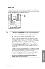
... MemOK! button lights continuously. It takes about 5-10 seconds. • If your system fails to boot up when the DIMM is tested. ASUS X99-E WS 1-13 Chapter 1 function. • The MemOK! button to boot after the whole tuning process, the DIAG_DRAM LED lights continuously. Press and ... We recommend that are not compatible with ones recommended in the Memory QVL (Qualified Vendors Lists) in this user manual or at www.asus.com. • If you download and update to memory tuning requirement, the system automatically reboots when each timing set is not properly...
... MemOK! button lights continuously. It takes about 5-10 seconds. • If your system fails to boot up when the DIMM is tested. ASUS X99-E WS 1-13 Chapter 1 function. • The MemOK! button to boot after the whole tuning process, the DIAG_DRAM LED lights continuously. Press and ... We recommend that are not compatible with ones recommended in the Memory QVL (Qualified Vendors Lists) in this user manual or at www.asus.com. • If you download and update to memory tuning requirement, the system automatically reboots when each timing set is not properly...

User Guide
Page 31
.... • You may change the EPU settings in the software application or BIOS setup program and enable the EPU function at the same time. Chapter 1 ASUS X99-E WS 1-15 EPU switch Enable this switch when the system is powered off. • The EPU LED (O2LED3) near the EPU switch lights up when you...
.... • You may change the EPU settings in the software application or BIOS setup program and enable the EPU function at the same time. Chapter 1 ASUS X99-E WS 1-15 EPU switch Enable this switch when the system is powered off. • The EPU LED (O2LED3) near the EPU switch lights up when you...

User Guide
Page 33
For the location of the EZ XMP LED, refer to enhance the DIMM's speed and performance. Chapter 1 ASUS X99-E WS 1-17 EZ XMP switch Enable this switch to overclock the installed DIMMs, allowing you enable the EZ XMP switch. The EZ XMP LED (XLED1) lights up when you to section 1.2.8 Onboard LEDs. 8.
For the location of the EZ XMP LED, refer to enhance the DIMM's speed and performance. Chapter 1 ASUS X99-E WS 1-17 EZ XMP switch Enable this switch to overclock the installed DIMMs, allowing you enable the EZ XMP switch. The EZ XMP LED (XLED1) lights up when you to section 1.2.8 Onboard LEDs. 8.

User Guide
Page 35
If an error is found, the critical component's LED stays lit up when the TPU switch is solved. 2. TPU LED (TPU_LED) The TPU LED lights up until the problem is enabled. Chapter 1 ASUS X99-E WS 1-19 1.2.8 Onboard LEDs 1. Diagnosis LEDs The Diagnosis LEDs provide the status of these key components during POST (PowerOn-Self Test): CPU, memory modules, VGA card, and hard disk drives.
If an error is found, the critical component's LED stays lit up when the TPU switch is solved. 2. TPU LED (TPU_LED) The TPU LED lights up until the problem is enabled. Chapter 1 ASUS X99-E WS 1-19 1.2.8 Onboard LEDs 1. Diagnosis LEDs The Diagnosis LEDs provide the status of these key components during POST (PowerOn-Self Test): CPU, memory modules, VGA card, and hard disk drives.

User Guide
Page 37
PWR_SUPPLY LED The ASUS Dr. Power LED near the Dr. Power switch lights up when the ASUS Dr. Power switch setting is enabled. 6. 5. ASUS Dr. Power LED (PGLED3) This LED near the EATX PWR connector lights up when the Dr. Power switch is on and the power supply unit has failed. Chapter 1 ASUS X99-E WS 1-21
PWR_SUPPLY LED The ASUS Dr. Power LED near the Dr. Power switch lights up when the ASUS Dr. Power switch setting is enabled. 6. 5. ASUS Dr. Power LED (PGLED3) This LED near the EATX PWR connector lights up when the Dr. Power switch is on and the power supply unit has failed. Chapter 1 ASUS X99-E WS 1-21

User Guide
Page 39
... by firmware (Auto recovery) Recovery condition triggered by user (Forced recovery) Recovery process started Recovery firmware image is found (continued on the next page) Chapter 1 ASUS X99-E WS 1-23
... by firmware (Auto recovery) Recovery condition triggered by user (Forced recovery) Recovery process started Recovery firmware image is found (continued on the next page) Chapter 1 ASUS X99-E WS 1-23
User Guide
Page 41
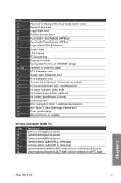
... entering S4 sleep state System is entering S5 sleep state System is waking up from the S3 sleep state System is in APIC mode. Chapter 1 ASUS X99-E WS 1-25 Code AC AD AE AF B0 B1 B2 B3 B4 B5 B6 B7 B8- Interrupt controller is waking up from the S4 sleep state...
... entering S4 sleep state System is entering S5 sleep state System is waking up from the S3 sleep state System is in APIC mode. Chapter 1 ASUS X99-E WS 1-25 Code AC AD AE AF B0 B1 B2 B3 B4 B5 B6 B7 B8- Interrupt controller is waking up from the S4 sleep state...

User Guide
Page 43
... behavior, the SATA6G_78 and SATA6G_910 ports (black) do not support Intel® Rapid Storage Technology and RAID configuration. Intel® X99 Serial ATA 6 Gb/s connectors (7-pin SATA6G_12, SATA6G_34, SATA6G_56/SATAEXPRESS_1, SATA6G_78, SATA6G_910) These connectors connect to [RAID Mode]. Refer...X99 chipset. If you installed Serial ATA hard disk drives, you intend to [AHCI Mode] by default. 3. Chapter 1 • These connectors are set , refer to the manual bundled in the BIOS to Serial ATA 6 Gb/s hard disk drives via Serial ATA 6 Gb/s signal cables. ASUS X99-E WS...
... behavior, the SATA6G_78 and SATA6G_910 ports (black) do not support Intel® Rapid Storage Technology and RAID configuration. Intel® X99 Serial ATA 6 Gb/s connectors (7-pin SATA6G_12, SATA6G_34, SATA6G_56/SATAEXPRESS_1, SATA6G_78, SATA6G_910) These connectors connect to [RAID Mode]. Refer...X99 chipset. If you installed Serial ATA hard disk drives, you intend to [AHCI Mode] by default. 3. Chapter 1 • These connectors are set , refer to the manual bundled in the BIOS to Serial ATA 6 Gb/s hard disk drives via Serial ATA 6 Gb/s signal cables. ASUS X99-E WS...
User Guide
Page 45
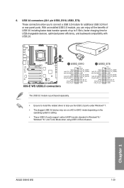
... panel ports. 6. With an installed USB 3.0 module, you to connect a USB 3.0 module for USB-chargeable devices, optimized power efficiency, and backward compatibility with USB 2.0. Chapter 1 ASUS X99-E WS 1-29 USB 3.0 connectors (20-1 pin USB3_E910, USB3_E78) These connectors allow you can enjoy all the benefits of USB 3.0 including faster data transfer speeds of up...
... panel ports. 6. With an installed USB 3.0 module, you to connect a USB 3.0 module for USB-chargeable devices, optimized power efficiency, and backward compatibility with USB 2.0. Chapter 1 ASUS X99-E WS 1-29 USB 3.0 connectors (20-1 pin USB3_E910, USB3_E78) These connectors allow you can enjoy all the benefits of USB 3.0 including faster data transfer speeds of up...

User Guide
Page 47
...! • Ensure that the black wire of each cable matches the ground pin of CPU fan installed and automatically switches the control modes. ASUS X99-E WS 1-31 To configure the CPU fan's control mode, go to the CPU fan connector. Insufficient air flow inside the system may damage the ...jumpers! CPU, CPU optional, and chassis fan connectors (4-pin CPU_FAN; 4-pin CPU_OPT; 4-pin CHA_FAN1-4) Connect the fan cables to the fan connectors on X99 platform. • The CPU fan connector detects the type of the connector. • DO NOT forget to connect the fan cables to Advanced Mode ...
...! • Ensure that the black wire of each cable matches the ground pin of CPU fan installed and automatically switches the control modes. ASUS X99-E WS 1-31 To configure the CPU fan's control mode, go to the CPU fan connector. Insufficient air flow inside the system may damage the ...jumpers! CPU, CPU optional, and chassis fan connectors (4-pin CPU_FAN; 4-pin CPU_OPT; 4-pin CHA_FAN1-4) Connect the fan cables to the fan connectors on X99 platform. • The CPU fan connector detects the type of the connector. • DO NOT forget to connect the fan cables to Advanced Mode ...

User Guide
Page 49
... several chassis-mounted functions. • System power LED (2-pin PLED) This 2-pin connector is for the chassis-mounted reset button for the system power button. ASUS X99-E WS 1-33 Chapter 1 Pressing the power switch for more than four seconds while the system is ON turns the system OFF. • Reset button (2-pin RESET...
... several chassis-mounted functions. • System power LED (2-pin PLED) This 2-pin connector is for the chassis-mounted reset button for the system power button. ASUS X99-E WS 1-33 Chapter 1 Pressing the power switch for more than four seconds while the system is ON turns the system OFF. • Reset button (2-pin RESET...

User Guide
Page 51
The add-on Thunderbolt I /O card and Thunderbolt cables are purchased separately. 14. M.2 socket 3 This socket allows you to connect up to install an M.2 (NGFF) SSD module. • This socket supports M Key and type 2260/2280 storage devices. • This socket supports PCIe mode only. Thunderbolt header (5-pin TB_HEADER) This connector is for the add-on Thunderbolt I /O card that supports Intel's Thunderbolt Technology, allowing you to six Thunderbolt-enabled devices and a DisplayPort-enabled display in a daisy-chain configuration. ASUS X99-E WS 1-35 Chapter 1 13.
The add-on Thunderbolt I /O card and Thunderbolt cables are purchased separately. 14. M.2 socket 3 This socket allows you to connect up to install an M.2 (NGFF) SSD module. • This socket supports M Key and type 2260/2280 storage devices. • This socket supports PCIe mode only. Thunderbolt header (5-pin TB_HEADER) This connector is for the add-on Thunderbolt I /O card that supports Intel's Thunderbolt Technology, allowing you to six Thunderbolt-enabled devices and a DisplayPort-enabled display in a daisy-chain configuration. ASUS X99-E WS 1-35 Chapter 1 13.

User Guide
Page 53
Chapter 1 ASUS X99-E WS 1-37 T_Sensor connector (2-pin T_SENSOR1) This connector is purchased separately. 16. The thermistor cable is for the thermistor cable that allows you to monitor the temperature of your motherboard's critical components and connected devices.
Chapter 1 ASUS X99-E WS 1-37 T_Sensor connector (2-pin T_SENSOR1) This connector is purchased separately. 16. The thermistor cable is for the thermistor cable that allows you to monitor the temperature of your motherboard's critical components and connected devices.


