
Terminator P4-533 English user''''s manual
Page 4
...42 3.6.3 IRQ assignments for this motherboard 42 3.7 Jumpers 43 3.8 Connectors 45 Chapter 4: BIOS Information 55 4.1 Managing and updating the BIOS 54 4.1.1 Using the computer system for the first time ......... 54 4.1.2 Updating BIOS procedures 56 4.2 BIOS Setup program 58 4.2.1 BIOS menu bar 59 4.2.2 Legend bar 59 4.3 Main Menu 61 4.3.1 Primary and Secondary ... system 90 5.2 Support CD information 90 5.2.1 Running the support CD 90 5.2.2 Installation menus 91 5.2.3 Software and drivers description 92 5.3 Software information 94 5.3.1 ASUS Update 94 5.3.2 ASUS PC Probe 96 4
...42 3.6.3 IRQ assignments for this motherboard 42 3.7 Jumpers 43 3.8 Connectors 45 Chapter 4: BIOS Information 55 4.1 Managing and updating the BIOS 54 4.1.1 Using the computer system for the first time ......... 54 4.1.2 Updating BIOS procedures 56 4.2 BIOS Setup program 58 4.2.1 BIOS menu bar 59 4.2.2 Legend bar 59 4.3 Main Menu 61 4.3.1 Primary and Secondary ... system 90 5.2 Support CD information 90 5.2.1 Running the support CD 90 5.2.2 Installation menus 91 5.2.3 Software and drivers description 92 5.3 Software information 94 5.3.1 ASUS Update 94 5.3.2 ASUS PC Probe 96 4

Terminator P4-533 English user''''s manual
Page 7
...This chapter gives information about the ASUS Terminator P4 533 Barebone System. Chapter 5: Starting up This chapter helps you power up your system and install drivers and utilities that came with hardware knowledge of personal computers. Chapter 1: System Introduction This chapter gives a general description of the BIOS parameters. 5. Chapter 2: Basic ... also includes information on the USB/audio board located on the front and rear panel features, and the internal features. 2. Chapter 4: BIOS information This chapter tells how to install components into the barebone system through the...
...This chapter gives information about the ASUS Terminator P4 533 Barebone System. Chapter 5: Starting up This chapter helps you power up your system and install drivers and utilities that came with hardware knowledge of personal computers. Chapter 1: System Introduction This chapter gives a general description of the BIOS parameters. 5. Chapter 2: Basic ... also includes information on the USB/audio board located on the front and rear panel features, and the internal features. 2. Chapter 4: BIOS information This chapter tells how to install components into the barebone system through the...
Terminator P4-533 English user''''s manual
Page 37
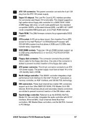
... system bus that allows 4.3GB/s and 3.2GB/s data transfer rates, respectively. 5 DDR DIMM sockets. This 2Mb firmware contains the programmable BIOS program. 4 CPU socket. Referred to prevent incorrect insertion of the floppy disk cable. 7 ATX power connector. The chipset supports a high... 2GB using unbuffered ECC or non-ECC PC2700/2100/1600 DDR DIMMs. 6 Floppy disk connector. This 20-pin connector connects to PCI Bridge. ASUS Terminator P4 533 Barebone System 37 A 478-pin surface mount, Zero Insertion Force (ZIF) socket for the floppy disk drive. 1 ATX 12V connector. This...
... system bus that allows 4.3GB/s and 3.2GB/s data transfer rates, respectively. 5 DDR DIMM sockets. This 2Mb firmware contains the programmable BIOS program. 4 CPU socket. Referred to prevent incorrect insertion of the floppy disk cable. 7 ATX power connector. The chipset supports a high... 2GB using unbuffered ECC or non-ECC PC2700/2100/1600 DDR DIMMs. 6 Floppy disk connector. This 20-pin connector connects to PCI Bridge. ASUS Terminator P4 533 Barebone System 37 A 478-pin surface mount, Zero Insertion Force (ZIF) socket for the floppy disk drive. 1 ATX 12V connector. This...

Terminator P4-533 English user''''s manual
Page 42
used - 42 Chapter 3: Motherboard information Turn on BIOS setup. 2. Refer to the card. Assign an IRQ to the tables below. 3. The motherboard has two PCI slots. 3.6.1 Configuring an expansion card After ...physically installing the expansion card, configure the card by adjusting the software settings. 1. See Chapter 4 for information on the system and change the necessary BIOS settings, if any. E F G H ---- ---- - used - ---- ---- used 10* 5 IRQ Holder for PCI Steering 11* 6 IRQ Holder for PCI Steering 12* 7 PS/2 Compatible Mouse Port 13 8 ...
used - 42 Chapter 3: Motherboard information Turn on BIOS setup. 2. Refer to the card. Assign an IRQ to the tables below. 3. The motherboard has two PCI slots. 3.6.1 Configuring an expansion card After ...physically installing the expansion card, configure the card by adjusting the software settings. 1. See Chapter 4 for information on the system and change the necessary BIOS settings, if any. E F G H ---- ---- - used - ---- ---- used 10* 5 IRQ Holder for PCI Steering 11* 6 IRQ Holder for PCI Steering 12* 7 PS/2 Compatible Mouse Port 13 8 ...

Terminator P4-533 English user''''s manual
Page 44
... by the onboard button cell battery. Turn OFF the computer and unplug the power cord. 2. Hold down the key during the boot process and enter BIOS setup to Clear CMOS 44 Chapter 3: Motherboard information
... by the onboard button cell battery. Turn OFF the computer and unplug the power cord. 2. Hold down the key during the boot process and enter BIOS setup to Clear CMOS 44 Chapter 3: Motherboard information

Terminator P4-533 English user''''s manual
Page 45
... to the UltraDMA/133/100/66 master device. It is removed to be both master devices with two ribbon cables - PIN 1 ASUS Terminator P4 533 Barebone System 45 If you install two hard disks, you connect non-UltraDMA/133/100/66 devices to the hard disk documentation for ...UltraDMA/133/100/66 cable. P4SC-E P4SC-E IDE Connectors IDE2 IDE1 NOTE: Orient the red markings (usually zigzag) on the motherboard. 1. BIOS supports specific device bootup. This prevents incorrect orientation when you have more than two UltraDMA/133/100/66 devices, purchase another for the jumper ...
... to the UltraDMA/133/100/66 master device. It is removed to be both master devices with two ribbon cables - PIN 1 ASUS Terminator P4 533 Barebone System 45 If you install two hard disks, you connect non-UltraDMA/133/100/66 devices to the hard disk documentation for ...UltraDMA/133/100/66 cable. P4SC-E P4SC-E IDE Connectors IDE2 IDE1 NOTE: Orient the red markings (usually zigzag) on the motherboard. 1. BIOS supports specific device bootup. This prevents incorrect orientation when you have more than two UltraDMA/133/100/66 devices, purchase another for the jumper ...

Terminator P4-533 English user''''s manual
Page 52
• ATX Power Switch / Soft-Off Switch Lead (2-pin PWR) This connector connects a switch that controls the system power. Pressing the power switch turns the system between ON and SLEEP, or ON and SOFT OFF, depending on the BIOS or OS settings. Pressing the power switch while in the ON mode for more than 4 seconds turns the system OFF. • Reset Switch Lead (2-pin RESET) This 2-pin connector connects to the case-mounted reset switch for rebooting the system without turning off the system power. 52 Chapter 3: Motherboard information
• ATX Power Switch / Soft-Off Switch Lead (2-pin PWR) This connector connects a switch that controls the system power. Pressing the power switch turns the system between ON and SLEEP, or ON and SOFT OFF, depending on the BIOS or OS settings. Pressing the power switch while in the ON mode for more than 4 seconds turns the system OFF. • Reset Switch Lead (2-pin RESET) This 2-pin connector connects to the case-mounted reset switch for rebooting the system without turning off the system power. 52 Chapter 3: Motherboard information

Terminator P4-533 English user''''s manual
Page 53
BIOS Information ASUS Terminator P4 533 Barebone System 53 It includes detailed descriptions of the BIOS parameters. Chapter 4 This chapter tells how to change system settings through the BIOS Setup menus.
BIOS Information ASUS Terminator P4 533 Barebone System 53 It includes detailed descriptions of the BIOS parameters. Chapter 4 This chapter tells how to change system settings through the BIOS Setup menus.
Terminator P4-533 English user''''s manual
Page 54
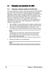
...CONFIG.SYS to create a bootable system disk. It is recommended that updates the BIOS by uploading a new BIOS file to reinstall the BIOS later. This file works only in DOS mode. Reboot the computer from the... hard drive. Larger numbers represent a newer BIOS file. 1. Type COPY D:\AFLASH\AFLASH.EXE A:\ (assuming D is your screen during bootup. ...to copy AFLASH.EXE to the boot disk you created. 4.1 Managing and updating the BIOS 4.1.1 Using the computer system for the first time It is recommended that may be loaded when ...
...CONFIG.SYS to create a bootable system disk. It is recommended that updates the BIOS by uploading a new BIOS file to reinstall the BIOS later. This file works only in DOS mode. Reboot the computer from the... hard drive. Larger numbers represent a newer BIOS file. 1. Type COPY D:\AFLASH\AFLASH.EXE A:\ (assuming D is your screen during bootup. ...to copy AFLASH.EXE to the boot disk you created. 4.1 Managing and updating the BIOS 4.1.1 Using the computer system for the first time It is recommended that may be loaded when ...

Terminator P4-533 English user''''s manual
Page 55
Select 1. Save Current BIOS to run AFLASH. IMPORTANT If the word "unknown" appears after Flash Memory:, the memory chip is either not programmable or is not supported by the ACPI BIOS and therefore, cannot be programmed by the Flash Memory Writer utility. 5. The Save Current BIOS To File screen appears. 6. In DOS mode, type A:\AFLASH to File from the Main menu and press . 4. ASUS Terminator P4 533 Barebone System 55 Type a filename and the path, for example, A:\XXX-XX.XXX, then press .
Select 1. Save Current BIOS to run AFLASH. IMPORTANT If the word "unknown" appears after Flash Memory:, the memory chip is either not programmable or is not supported by the ACPI BIOS and therefore, cannot be programmed by the Flash Memory Writer utility. 5. The Save Current BIOS To File screen appears. 6. In DOS mode, type A:\AFLASH to File from the Main menu and press . 4. ASUS Terminator P4 533 Barebone System 55 Type a filename and the path, for example, A:\XXX-XX.XXX, then press .

Terminator P4-533 English user''''s manual
Page 56
Boot from the Internet (WWW or FTP) (see ASUS CONTACT INFORMATION on page x for details) and save to more problems with the motherboard and you are sure that the new BIOS revision will solve your new BIOS and the path, for example, A:\XXX-XX.XXX, then press ...problems with the motherboard! 1. The Update BIOS Including Boot Block and ESCD screen appears. 5. Download an updated ASUS BIOS file from the floppy disk. 3. When prompted to confirm the BIOS update, press Y to start the update. 56 Chapter 4: BIOS information 4.1.2 Updating BIOS procedures CAUTION! At the "A:\" prompt, type...
Boot from the Internet (WWW or FTP) (see ASUS CONTACT INFORMATION on page x for details) and save to more problems with the motherboard and you are sure that the new BIOS revision will solve your new BIOS and the path, for example, A:\XXX-XX.XXX, then press ...problems with the motherboard! 1. The Update BIOS Including Boot Block and ESCD screen appears. 5. Download an updated ASUS BIOS file from the floppy disk. 3. When prompted to confirm the BIOS update, press Y to start the update. 56 Chapter 4: BIOS information 4.1.2 Updating BIOS procedures CAUTION! At the "A:\" prompt, type...

Terminator P4-533 English user''''s manual
Page 57
When the programming is updated automatically only when necessary. Follow the onscreen instructions to program the new BIOS information into the Flash ROM. If this may not boot. ASUS Terminator P4 533 Barebone System 57 The utility starts to continue. The boot block is done, the message "Flashed Successfully" appears. 8. WARNING...boot problems in case of update failures. 7. If the Flash Memory Writer utility is not able to successfully update a complete BIOS file, the system may cause boot problems. Just repeat the process, and if the problem persists, load the original...
When the programming is updated automatically only when necessary. Follow the onscreen instructions to program the new BIOS information into the Flash ROM. If this may not boot. ASUS Terminator P4 533 Barebone System 57 The utility starts to continue. The boot block is done, the message "Flashed Successfully" appears. 8. WARNING...boot problems in case of update failures. 7. If the Flash Memory Writer utility is not able to successfully update a complete BIOS file, the system may cause boot problems. Just repeat the process, and if the problem persists, load the original...

Terminator P4-533 English user''''s manual
Page 58
... on the motherboard stores the Setup utility. You can also restart by pressing the reset button on your screen. 58 Chapter 4: BIOS information This section explains how to use as possible. Even if you are not prompted to configure your system using the provided utility... described in section "4.1 Managing and updating your BIOS." 4.2 BIOS Setup program This motherboard supports a programmable EEPROM that the computer can recognize these changes and record them in the CMOS RAM of your...
... on the motherboard stores the Setup utility. You can also restart by pressing the reset button on your screen. 58 Chapter 4: BIOS information This section explains how to use as possible. Even if you are not prompted to configure your system using the provided utility... described in section "4.1 Managing and updating your BIOS." 4.2 BIOS Setup program This motherboard supports a programmable EEPROM that the computer can recognize these changes and record them in the CMOS RAM of your...

Terminator P4-533 English user''''s manual
Page 59
...for the highlighted field Scrolls forward through the various setup menus. EXIT Use this menu to its Setup Defaults Saves changes and exits Setup ASUS Terminator P4 533 Barebone System 59 The keys in the legend bar allow you to navigate through the values for the highlighted field Brings up a selection menu... functions. BOOT Use this menu to enable and make changes to the advanced features. The following table lists the keys found in the BIOS Setup Jumps to the Exit menu or returns to the main menu from anywhere in the legend bar with the following selections: MAIN Use...
...for the highlighted field Scrolls forward through the various setup menus. EXIT Use this menu to its Setup Defaults Saves changes and exits Setup ASUS Terminator P4 533 Barebone System 59 The keys in the legend bar allow you to navigate through the values for the highlighted field Brings up a selection menu... functions. BOOT Use this menu to enable and make changes to the advanced features. The following table lists the keys found in the BIOS Setup Jumps to the Exit menu or returns to the main menu from anywhere in the legend bar with the following selections: MAIN Use...

Terminator P4-533 English user''''s manual
Page 60
... yourself with the legend keys and their corresponding functions. Use and or the up and down arrow keys to the Item Specific Help window, the BIOS setup program also provides a General Help screen. Take some time to the main menu. Practice navigating through the entire help text for the currently highlighted...
... yourself with the legend keys and their corresponding functions. Use and or the up and down arrow keys to the Item Specific Help window, the BIOS setup program also provides a General Help screen. Take some time to the main menu. Practice navigating through the entire help text for the currently highlighted...

Terminator P4-533 English user''''s manual
Page 62
...not set a Supervisor password, anyone can type up to eight alphanumeric characters. Type in the Main menu. The password is required to enter the BIOS Setup program and to gain full access to the configuration fields. If you did , the Supervisor password is now set passwords. See section "3.7 ..., you to specify two different passwords: a Supervisor password and a User password. This password allows full access to erase the RTC RAM. The BIOS Setup program allows you can clear it by erasing the CMOS Real Time Clock (RTC) RAM. To confirm the password, type the password again ...
...not set a Supervisor password, anyone can type up to eight alphanumeric characters. Type in the Main menu. The password is required to enter the BIOS Setup program and to gain full access to the configuration fields. If you did , the Supervisor password is now set passwords. See section "3.7 ..., you to specify two different passwords: a Supervisor password and a User password. This password allows full access to erase the RTC RAM. The BIOS Setup program allows you can clear it by erasing the CMOS Real Time Clock (RTC) RAM. To confirm the password, type the password again ...
Terminator P4-533 English user''''s manual
Page 64
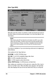
... and not replacing it, select [None]. NOTE After entering the IDE hard disk drive information into BIOS, use a disk utility, such as FDISK, to active. This is installed or if you configured. 64 Chapter 4: BIOS information When the Main menu appears, the hard disk drive field displays the size for the drive...
... and not replacing it, select [None]. NOTE After entering the IDE hard disk drive information into BIOS, use a disk utility, such as FDISK, to active. This is installed or if you configured. 64 Chapter 4: BIOS information When the Main menu appears, the hard disk drive field displays the size for the drive...

Terminator P4-533 English user''''s manual
Page 65
...set the Type field to [User Type HDD]. CHS Capacity This field shows the drive's maximum CHS capacity as calculated by the BIOS based on the drive information you entered. You may not always be the fastest value for the drive. Refer to the documentation ... correct value. To make changes to this field. Configuration options: [Disabled] [2 Sectors] [4 Sectors] [8 Sectors] [16 Sectors] [32 Sectors] [Maximum] ASUS Terminator P4 533 Barebone System 65 When Logical Block Addressing (LBA) is enabled, the 28-bit addressing of the hard drive is automatically configured, the set value may...
...set the Type field to [User Type HDD]. CHS Capacity This field shows the drive's maximum CHS capacity as calculated by the BIOS based on the drive information you entered. You may not always be the fastest value for the drive. Refer to the documentation ... correct value. To make changes to this field. Configuration options: [Disabled] [2 Sectors] [4 Sectors] [8 Sectors] [16 Sectors] [32 Sectors] [Maximum] ASUS Terminator P4 533 Barebone System 65 When Logical Block Addressing (LBA) is enabled, the 28-bit addressing of the hard drive is automatically configured, the set value may...

Terminator P4-533 English user''''s manual
Page 66
... because the resources used in performance. Modes 0 through 4 provide successive increase in the SMART monitoring feature may decrease system performance. Configuration options: [0] [1] [2] [3] [4] [5] [Disabled] 66 Chapter 4: BIOS information Configuration options: [0] [1] [2] [3] [4] Ultra DMA Mode [Disabled] Ultra DMA capability allows improved transfer speeds and data integrity for the IDE device. Configuration options: [Disabled] [Enabled...
... because the resources used in performance. Modes 0 through 4 provide successive increase in the SMART monitoring feature may decrease system performance. Configuration options: [0] [1] [2] [3] [4] [5] [Disabled] 66 Chapter 4: BIOS information Configuration options: [0] [1] [2] [3] [4] Ultra DMA Mode [Disabled] Ultra DMA capability allows improved transfer speeds and data integrity for the IDE device. Configuration options: [Disabled] [Enabled...

Terminator P4-533 English user''''s manual
Page 68
...] CAUTION Be careful when setting the CPU internal frequency. The bus frequency (external frequency) multiplied by the bus multiple equals the CPU speed. 68 Chapter 4: BIOS information Selecting a frequency higher than what frequency to send to hang or crash! This field sets the frequency multiple between the CPU's internal frequency (CPU...
...] CAUTION Be careful when setting the CPU internal frequency. The bus frequency (external frequency) multiplied by the bus multiple equals the CPU speed. 68 Chapter 4: BIOS information Selecting a frequency higher than what frequency to send to hang or crash! This field sets the frequency multiple between the CPU's internal frequency (CPU...


