Terminator P4/533 Driver - Asus P4 533
Terminator P4/533 Driver
View Results Below
Free Asus Terminator P4 533 manuals!
Problems with Asus Terminator P4 533?
Ask a Question
Free Asus Terminator P4 533 manuals!
Problems with Asus Terminator P4 533?
Ask a Question
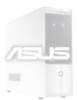
Related Manual Pages

Similar Questions

Driver Asus Pundit P1-ph1 P5r8l Free
I Want Download Driver Asus Pundit P1-ph1 P5r8l Free
I Want Download Driver Asus Pundit P1-ph1 P5r8l Free
(Posted by KHATTAB2000MAHMOUD 9 years ago)


Hi I Need To Asus Et2400igts Camera Driver???wher I Get Driver??
hi i need to asus ET2400IGTS camera driver???wher i get driver??
hi i need to asus ET2400IGTS camera driver???wher i get driver??
(Posted by vipuziss 11 years ago)