

User Guide
Page 15
1.2 Serial number label Before requesting support from the ASUS Technical Support team, you must take note of the product, ASUS Technical Support team members can then offer a quicker and satisfying solution to your problems. TS500-E8-PS4 xxS0xxxxxxxxxx ASUS TS500-E8-PS4 1-3 With the correct serial number of the product's serial number containing 14 characters such as xxS0xxxxxxxxxx shown as the figure below.
1.2 Serial number label Before requesting support from the ASUS Technical Support team, you must take note of the product, ASUS Technical Support team members can then offer a quicker and satisfying solution to your problems. TS500-E8-PS4 xxS0xxxxxxxxxx ASUS TS500-E8-PS4 1-3 With the correct serial number of the product's serial number containing 14 characters such as xxS0xxxxxxxxxx shown as the figure below.

User Guide
Page 16
...® I210AT 1 x Management port Aspeed AST2400 32MB (continued on the next page) 1-4 Chapter 1: Product introduction 1.3 System specifications The ASUS TS500-E8-PS4 is a 5U barebone server system featuring the ASUS Z10PA-D8 Server Board. Model Name TS500-E8-PS4 2 x Socket R3 LGA 2011-3 Processor Support / System Intel® Xeon® Processor E5-2600 v3 product Family Bus QPI...
...® I210AT 1 x Management port Aspeed AST2400 32MB (continued on the next page) 1-4 Chapter 1: Product introduction 1.3 System specifications The ASUS TS500-E8-PS4 is a 5U barebone server system featuring the ASUS Z10PA-D8 Server Board. Model Name TS500-E8-PS4 2 x Socket R3 LGA 2011-3 Processor Support / System Intel® Xeon® Processor E5-2600 v3 product Family Bus QPI...
User Guide
Page 17
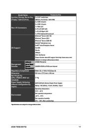
Model Name Auxiliary Storage Device Bay (Floppy / Optical Drive) TS500-E8-PS4 3 x 5.25" media bays (Options: No Device / DVD-RW) 2 x USB 2.0 ports 2 x USB 3.0 ports Rear I/O Connectors 1 x VGA port 2...Linux Enterprise Server OS Support CentOS Ubuntu VMware Citrix XenServer Please find the latest OS support from http://www.asus.com/ Management Solution Software Out of Band Remote Management (Subject to change without any notice) ASWM Enterprise ...176;C Non operation humidity: 20% - 90% (Non condensing) *Specifications are subject to change without notice. ASUS TS500-E8-PS4 1-5
Model Name Auxiliary Storage Device Bay (Floppy / Optical Drive) TS500-E8-PS4 3 x 5.25" media bays (Options: No Device / DVD-RW) 2 x USB 2.0 ports 2 x USB 3.0 ports Rear I/O Connectors 1 x VGA port 2...Linux Enterprise Server OS Support CentOS Ubuntu VMware Citrix XenServer Please find the latest OS support from http://www.asus.com/ Management Solution Software Out of Band Remote Management (Subject to change without any notice) ASWM Enterprise ...176;C Non operation humidity: 20% - 90% (Non condensing) *Specifications are subject to change without notice. ASUS TS500-E8-PS4 1-5

User Guide
Page 19
1.5 Rear panel features PS/2 mouse/keyboard port USB 2.0 ports VGA port Gigabit LAN ports USB 3.0 ports *This port is for the ASUS ASMB8-iKVM controller only. Power connector Chassis lock 120mm x 38mm system fan LAN port* Chassis intrusion switch Expansion slots ASUS TS500-E8-PS4 1-7
1.5 Rear panel features PS/2 mouse/keyboard port USB 2.0 ports VGA port Gigabit LAN ports USB 3.0 ports *This port is for the ASUS ASMB8-iKVM controller only. Power connector Chassis lock 120mm x 38mm system fan LAN port* Chassis intrusion switch Expansion slots ASUS TS500-E8-PS4 1-7
User Guide
Page 21
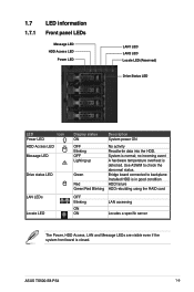
... Display status ON Description System power ON OFF Blinking OFF Lighting up Green Red Green/Red Blinking No activity Read/write data into the HDD. ASUS TS500-E8-PS4 1-9 no incoming event A hardware temperature overheat is normal; Bridge board connected to check the abnormal status. System is detected. Use ASWM to backplane Installed HDD...
... Display status ON Description System power ON OFF Blinking OFF Lighting up Green Red Green/Red Blinking No activity Read/write data into the HDD. ASUS TS500-E8-PS4 1-9 no incoming event A hardware temperature overheat is normal; Bridge board connected to check the abnormal status. System is detected. Use ASWM to backplane Installed HDD...

User Guide
Page 25
Drive in place. 3. 2.1.2 Reinstalling the side cover To reinstall the side cover: 1. Slide the side cover toward the front panel until it snaps in the two screws you removed earlier to the corresponding chassis edge. 1 2. Match and insert the lower sliding edge of the side cover to secure the side cover. 3 2 3 ASUS TS500-E8-PS4 2-3
Drive in place. 3. 2.1.2 Reinstalling the side cover To reinstall the side cover: 1. Slide the side cover toward the front panel until it snaps in the two screws you removed earlier to the corresponding chassis edge. 1 2. Match and insert the lower sliding edge of the side cover to secure the side cover. 3 2 3 ASUS TS500-E8-PS4 2-3

User Guide
Page 27
ASUS TS500-E8-PS4 2-5 2. Load lever 3. Press the left until it is released from then gently lift the load lever (F). Press the right load lever with your thumb (A), move it to the left load lever down with your thumb (D), move it to the right until it is released from the retention tab (B) then gently lift the load lever (C). To prevent damage to the socket pins, do not remove the PnP cap unless you are installing a CPU.
ASUS TS500-E8-PS4 2-5 2. Load lever 3. Press the left until it is released from then gently lift the load lever (F). Press the right load lever with your thumb (A), move it to the left load lever down with your thumb (D), move it to the right until it is released from the retention tab (B) then gently lift the load lever (C). To prevent damage to the socket pins, do not remove the PnP cap unless you are installing a CPU.

User Guide
Page 29
... process Return Merchandise Authorization (RMA) requests only if the motherboard comes with the PnP cap on the LGA 2011-3 socket. Retention tab ASUS TS500-E8-PS4 2-7 The PnP cap pops out of the load plate is inserted into the retention tab. Push down the right load lever (I) ensuring that the edge ...
... process Return Merchandise Authorization (RMA) requests only if the motherboard comes with the PnP cap on the LGA 2011-3 socket. Retention tab ASUS TS500-E8-PS4 2-7 The PnP cap pops out of the load plate is inserted into the retention tab. Push down the right load lever (I) ensuring that the edge ...

User Guide
Page 31
Loose the rear fan retainers with both hands to CPU_FAN2 connector. 3. Connect the CPU heatsink fan connector to remove the fan and unplug the rear fan connector. 2. 2.2.2 Installing the CPU heatsink To install the CPU heatsink: 1. Align and click the rear fan into place. ASUS TS500-E8-PS4 2-9 Connect the rear fan connector to REAR_FAN1 connector.
Loose the rear fan retainers with both hands to CPU_FAN2 connector. 3. Connect the CPU heatsink fan connector to remove the fan and unplug the rear fan connector. 2. 2.2.2 Installing the CPU heatsink To install the CPU heatsink: 1. Align and click the rear fan into place. ASUS TS500-E8-PS4 2-9 Connect the rear fan connector to REAR_FAN1 connector.

User Guide
Page 33
2.3 System memory 2.3.1 Overview The motherboard comes with eight (8) Double Data Rate 4 (DDR4) Dual Inline Memory Modules (DIMM) sockets. The figure illustrates the location of the DDR4 DIMM sockets: ASUS TS500-E8-PS4 2-11
2.3 System memory 2.3.1 Overview The motherboard comes with eight (8) Double Data Rate 4 (DDR4) Dual Inline Memory Modules (DIMM) sockets. The figure illustrates the location of the DDR4 DIMM sockets: ASUS TS500-E8-PS4 2-11

User Guide
Page 35
.... Locked Retaining Clip Always insert the DIMM into place and the DIMM is keyed with extra force. Remove the DIMM from a single clip DIMM socket 1. ASUS TS500-E8-PS4 2-13
.... Locked Retaining Clip Always insert the DIMM into place and the DIMM is keyed with extra force. Remove the DIMM from a single clip DIMM socket 1. ASUS TS500-E8-PS4 2-13

User Guide
Page 37
The lower bays (labeled 2 and 3) are available for additional 5.25-inch optical, zip, or floppy disk drives. ASUS TS500-E8-PS4 2-15 Unscrew and remove the metal cover of the drive. You must remove the front panel assembly before installing or removing any system components. Installing a 5....
The lower bays (labeled 2 and 3) are available for additional 5.25-inch optical, zip, or floppy disk drives. ASUS TS500-E8-PS4 2-15 Unscrew and remove the metal cover of the drive. You must remove the front panel assembly before installing or removing any system components. Installing a 5....

User Guide
Page 39
Disconnect all the cables from the SATA/SAS backplane on the HDD module cage. 2. Completely pull out the HDD module cage. ASUS TS500-E8-PS4 2-17 The HDD module cage will be pushed out of the chassis. 2 3. Level the HDD module cage latch counterclockwise. 2.6.2 Removing the HDD module cage 1.
Disconnect all the cables from the SATA/SAS backplane on the HDD module cage. 2. Completely pull out the HDD module cage. ASUS TS500-E8-PS4 2-17 The HDD module cage will be pushed out of the chassis. 2 3. Level the HDD module cage latch counterclockwise. 2.6.2 Removing the HDD module cage 1.

User Guide
Page 41
When installed, the SATA/SAS connector on the drive connects to install a second SATA/SAS drive. ASUS TS500-E8-PS4 2-19 4. Carefully insert the drive tray and push it clicks, and secures the drive tray in place. Repeat steps 1 to 6 if you wish to the ...
When installed, the SATA/SAS connector on the drive connects to install a second SATA/SAS drive. ASUS TS500-E8-PS4 2-19 4. Carefully insert the drive tray and push it clicks, and secures the drive tray in place. Repeat steps 1 to 6 if you wish to the ...

User Guide
Page 43
...! 2.7.1 Installing an expansion card 1. Remove the metal slot cover opposite the slot where you to install or remove an expansion card in the right figure. ASUS TS500-E8-PS4 2-21
...! 2.7.1 Installing an expansion card 1. Remove the metal slot cover opposite the slot where you to install or remove an expansion card in the right figure. ASUS TS500-E8-PS4 2-21

User Guide
Page 45
2.8 Cable connections 2.8.1 The bundled system cables are pre-connected before shipment. You do not need to disconnect these cables unless you will remove pre‑installed components to Chapter 4 for detailed information on the connectors. Refer to install additional devices. Motherboard connections 1 2 23 ASUS TS500-E8-PS4 6 5 4 7 5 2-23
2.8 Cable connections 2.8.1 The bundled system cables are pre-connected before shipment. You do not need to disconnect these cables unless you will remove pre‑installed components to Chapter 4 for detailed information on the connectors. Refer to install additional devices. Motherboard connections 1 2 23 ASUS TS500-E8-PS4 6 5 4 7 5 2-23

User Guide
Page 47
... to the table for reference. HDD Device HDD 1 HDD 2 HDD 3 HDD 4 Front side connector HDD1 HDD2 HDD3 HDD4 Back side connector CON1 CON2 CON3 CON4 ASUS TS500-E8-PS4 2-25 Refer to indicate HDD status. The backplane design incorporates a hot swap feature to support Serial ATA hard disk drives and SAS hard disk drives... to allow easy connection or removal of SATA/SAS hard disks. 2.8.2 SATA/SAS backplane connections A SATA/SAS backplane comes pre-installed in the TS700-X7/PS4.
... to the table for reference. HDD Device HDD 1 HDD 2 HDD 3 HDD 4 Front side connector HDD1 HDD2 HDD3 HDD4 Back side connector CON1 CON2 CON3 CON4 ASUS TS500-E8-PS4 2-25 Refer to indicate HDD status. The backplane design incorporates a hot swap feature to support Serial ATA hard disk drives and SAS hard disk drives... to allow easy connection or removal of SATA/SAS hard disks. 2.8.2 SATA/SAS backplane connections A SATA/SAS backplane comes pre-installed in the TS700-X7/PS4.

User Guide
Page 49
... fan To remove the front system fan: 1. Remove the two screws that secure the right side cover. 1 1 2. This section tells how to replace defective components. a b a ASUS TS500-E8-PS4 2-27 2.9 Removable components You may need to remove previously installed system components when installing or removing system devices, or when you need to remove the...
... fan To remove the front system fan: 1. Remove the two screws that secure the right side cover. 1 1 2. This section tells how to replace defective components. a b a ASUS TS500-E8-PS4 2-27 2.9 Removable components You may need to remove previously installed system components when installing or removing system devices, or when you need to remove the...

User Guide
Page 51
Repeat step 1 and 2 to Chapter 3: Installation options of the chassis for instructions) To remove the footpads: 1. ASUS TS500-E8-PS4 2-29 2.9.2 Chassis footpads The barebone server system is shipped with a Philips (cross) screwdriver. 3. Remove the footpad by rotating it counterclockwise with four footpads attached to the bottom of this user guide, and to the "Rackmount Kit" user guide for stability. You need to remove these footpads if you wish to install the system to a rack (Refer to remove the other three footpads. Lay the system chassis on its side. 2.
Repeat step 1 and 2 to Chapter 3: Installation options of the chassis for instructions) To remove the footpads: 1. ASUS TS500-E8-PS4 2-29 2.9.2 Chassis footpads The barebone server system is shipped with a Philips (cross) screwdriver. 3. Remove the footpad by rotating it counterclockwise with four footpads attached to the bottom of this user guide, and to the "Rackmount Kit" user guide for stability. You need to remove these footpads if you wish to install the system to a rack (Refer to remove the other three footpads. Lay the system chassis on its side. 2.
User Guide
Page 55
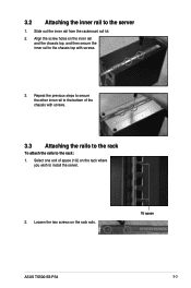
3.2 Attaching the inner rail to the rack: 1. Repeat the previous steps to secure the other inner rail to the bottom of space (1U) on the rack where you wish to install the server. 2. Align the screw holes on the rack rails. 1U space ASUS TS500-E8-PS4 3-3 Loosen the two screws on the inner rail and the chassis top, and then secure the inner rail to the chassis top with screws. 3.3 Attaching the rails to the rack To attach the rails to the server 1. Select one unit of the chassis with screws. 3. Slide out the inner rail from the rackmount rail kit. 2.
3.2 Attaching the inner rail to the rack: 1. Repeat the previous steps to secure the other inner rail to the bottom of space (1U) on the rack where you wish to install the server. 2. Align the screw holes on the rack rails. 1U space ASUS TS500-E8-PS4 3-3 Loosen the two screws on the inner rail and the chassis top, and then secure the inner rail to the chassis top with screws. 3.3 Attaching the rails to the rack To attach the rails to the server 1. Select one unit of the chassis with screws. 3. Slide out the inner rail from the rackmount rail kit. 2.


