

User Guide
Page 5
...ME Configuration 5-38 5.5.10 Runtime Error Logging Support 5-39 5.6 Server Mgmt menu 5-39 5.7 Event Logs menu 5-44 5.7.1 Change Smbios Event Log Settings 5-44 5.7.2 View Smbios Event Log 5-45 5.8 Monitor menu 5-46 5.9 Security menu 5-47 5.10 Boot menu 5-50 5.11 Tool menu 5-51 5.12 Exit menu 5-52 Chapter 6: RAID Configuration 6.1 Setting up RAID 6-2 6.1.1 RAID definitions 6-2 6.1.2 Installing hard disk drives 6-3 6.1.3 Setting the RAID item in BIOS 6-3 6.1.4 RAID configuration utilities 6-3 6.2 LSI Software RAID Configuration Utility (Z10PA-D8 only 6-4 6.2.1 Creating a RAID set...
...ME Configuration 5-38 5.5.10 Runtime Error Logging Support 5-39 5.6 Server Mgmt menu 5-39 5.7 Event Logs menu 5-44 5.7.1 Change Smbios Event Log Settings 5-44 5.7.2 View Smbios Event Log 5-45 5.8 Monitor menu 5-46 5.9 Security menu 5-47 5.10 Boot menu 5-50 5.11 Tool menu 5-51 5.12 Exit menu 5-52 Chapter 6: RAID Configuration 6.1 Setting up RAID 6-2 6.1.1 RAID definitions 6-2 6.1.2 Installing hard disk drives 6-3 6.1.3 Setting the RAID item in BIOS 6-3 6.1.4 RAID configuration utilities 6-3 6.2 LSI Software RAID Configuration Utility (Z10PA-D8 only 6-4 6.2.1 Creating a RAID set...

User Guide
Page 6
...Option ROM utility 6-29 6.3.5 Rebuilding the RAID 6-29 6.3.6 Setting the Boot array in the BIOS Setup Utility 6-31 6.4 Intel® Rapid Storage Technology enterprise (Windows 6-32 6.4.1 Creating a RAID set 6-33 6.4.2 Changing a Volume Type 6-35 6.4.3 Deleting a volume 6-36 6.4.4 Preferences 6-37 Chapter 7: Driver installation 7.1 RAID driver installation 7-2 7.1.1 Creating a RAID driver disk 7-2 7.1.2 Installing the RAID controller driver 7-3 7.2 Management applications and utilities installation 7-13 7.3 Running the Support DVD 7-13 7.4 Intel® chipset device software...
...Option ROM utility 6-29 6.3.5 Rebuilding the RAID 6-29 6.3.6 Setting the Boot array in the BIOS Setup Utility 6-31 6.4 Intel® Rapid Storage Technology enterprise (Windows 6-32 6.4.1 Creating a RAID set 6-33 6.4.2 Changing a Volume Type 6-35 6.4.3 Deleting a volume 6-36 6.4.4 Preferences 6-37 Chapter 7: Driver installation 7.1 RAID driver installation 7-2 7.1.1 Creating a RAID driver disk 7-2 7.1.2 Installing the RAID controller driver 7-3 7.2 Management applications and utilities installation 7-13 7.3 Running the Support DVD 7-13 7.4 Intel® chipset device software...

User Guide
Page 10
... configuring RAID sets using the available utilities. 7. Chapter 4: Motherboard information This chapter includes the motherboard layout and brief descriptions of configuring a server. Chapter 5: BIOS information This chapter tells how to install optional components into the barebone server. 4. x Chapter 6: RAID configuration This chapter provides instructions for different system components. Chapter 1: Product introduction This chapter describes the general features of the server, including sections on front panel and rear panel specifications. 2. Chapter 2: Hardware setup...
... configuring RAID sets using the available utilities. 7. Chapter 4: Motherboard information This chapter includes the motherboard layout and brief descriptions of configuring a server. Chapter 5: BIOS information This chapter tells how to install optional components into the barebone server. 4. x Chapter 6: RAID configuration This chapter provides instructions for different system components. Chapter 1: Product introduction This chapter describes the general features of the server, including sections on front panel and rear panel specifications. 2. Chapter 2: Hardware setup...

User Guide
Page 11
IMPORTANT: Instructions that you perform certain tasks properly, take note of the following symbols used throughout this manual. NOTE: Tips and additional information to complete a task. CAUTION: Information to prevent damage to the components when trying to help you complete a task. DANGER/WARNING: Information to prevent injury to yourself when trying to complete a task. Typography Bold text Italics + Conventions To ensure that you MUST follow to complete a task.
IMPORTANT: Instructions that you perform certain tasks properly, take note of the following symbols used throughout this manual. NOTE: Tips and additional information to complete a task. CAUTION: Information to prevent damage to the components when trying to help you complete a task. DANGER/WARNING: Information to prevent injury to yourself when trying to complete a task. Typography Bold text Italics + Conventions To ensure that you MUST follow to complete a task.
User Guide
Page 17
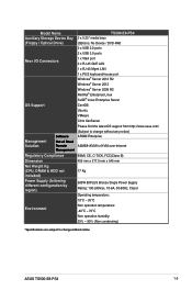
... Drive) TS500-E8-PS4 3 x 5.25" media bays (Options: No Device / DVD-RW) 2 x USB 2.0 ports 2 x USB 3.0 ports Rear I/O Connectors 1 x VGA port 2 x RJ-45 GbE LAN 1 x RJ-45 Mgmt LAN 1 x PS/2 keyboard/mouse port Windows® Server 2012 R2 Windows® Server 2012 Windows® Server 2008 R2 RedHat® Enterprise Linux SuSE® Linux Enterprise Server OS Support CentOS Ubuntu VMware Citrix XenServer Please find the latest OS support from http://www.asus.com/ Management Solution Software Out of Band Remote Management (Subject...
... Drive) TS500-E8-PS4 3 x 5.25" media bays (Options: No Device / DVD-RW) 2 x USB 2.0 ports 2 x USB 3.0 ports Rear I/O Connectors 1 x VGA port 2 x RJ-45 GbE LAN 1 x RJ-45 Mgmt LAN 1 x PS/2 keyboard/mouse port Windows® Server 2012 R2 Windows® Server 2012 Windows® Server 2008 R2 RedHat® Enterprise Linux SuSE® Linux Enterprise Server OS Support CentOS Ubuntu VMware Citrix XenServer Please find the latest OS support from http://www.asus.com/ Management Solution Software Out of Band Remote Management (Subject...

User Guide
Page 35
.... ASUS TS500-E8-PS4 2-13 DIMM slot key Unlocked retaining clip A DIMM is seated securely in only one direction. Press the retaining clip outward to unlock the DIMM. 2. Support the DIMM lightly with a notch so that the notch on the DIMM matches the DIMM slot key on a single clip DIMM socket 1. Hold the DIMM at both ends of the memory modules. Press the retaining clip outward to unlock the DIMM socket. 2.3.3 Installing a DIMM...
.... ASUS TS500-E8-PS4 2-13 DIMM slot key Unlocked retaining clip A DIMM is seated securely in only one direction. Press the retaining clip outward to unlock the DIMM. 2. Support the DIMM lightly with a notch so that the notch on the DIMM matches the DIMM slot key on a single clip DIMM socket 1. Hold the DIMM at both ends of the memory modules. Press the retaining clip outward to unlock the DIMM socket. 2.3.3 Installing a DIMM...

User Guide
Page 43
Remove the metal slot cover opposite the slot where you to the motherboard and other system components! 2.7.1 Installing an expansion card 1. ASUS TS500-E8-PS4 2-21 Ensure to install an expansion card. Before installing the expansion card, read the documentation that came with an expansion card lock on a flat, stable surface. 3. b 4. Lay the system on its side on the rear panel for the card. 2. 2.7 Expansion cards The system is designed with it and make the necessary hardware settings for...
Remove the metal slot cover opposite the slot where you to the motherboard and other system components! 2.7.1 Installing an expansion card 1. ASUS TS500-E8-PS4 2-21 Ensure to install an expansion card. Before installing the expansion card, read the documentation that came with an expansion card lock on a flat, stable surface. 3. b 4. Lay the system on its side on the rear panel for the card. 2. 2.7 Expansion cards The system is designed with it and make the necessary hardware settings for...

User Guide
Page 47
... side of the SATA/SAS backplane faces the front panel when installed. HDD Device HDD 1 HDD 2 HDD 3 HDD 4 Front side connector HDD1 HDD2 HDD3 HDD4 Back side connector CON1 CON2 CON3 CON4 ASUS TS500-E8-PS4 2-25 2.8.2 SATA/SAS backplane connections A SATA/SAS backplane comes pre-installed in the TS700-X7/PS4. Refer to support Serial ATA hard disk drives and SAS hard disk drives. Front side The front side of the backplane. The SATA/SAS backplane has four 22-pin SATA/SAS connectors to the table...
... side of the SATA/SAS backplane faces the front panel when installed. HDD Device HDD 1 HDD 2 HDD 3 HDD 4 Front side connector HDD1 HDD2 HDD3 HDD4 Back side connector CON1 CON2 CON3 CON4 ASUS TS500-E8-PS4 2-25 2.8.2 SATA/SAS backplane connections A SATA/SAS backplane comes pre-installed in the TS700-X7/PS4. Refer to support Serial ATA hard disk drives and SAS hard disk drives. Front side The front side of the backplane. The SATA/SAS backplane has four 22-pin SATA/SAS connectors to the table...

User Guide
Page 49
... power supply module 2.9.1 System fan Removing the front system fan To remove the front system fan: 1. Follow the previous instructions in the right figure. 4. Chassis footpads 3. Squeeze the front system fan latches (step a) and pull out the front system fan (step b), as shown in reverse to replace defective components. System fans (front and rear) 2. a b a ASUS TS500-E8-PS4 2-27 2.9 Removable components You may need to remove previously installed system components when installing or removing...
... power supply module 2.9.1 System fan Removing the front system fan To remove the front system fan: 1. Follow the previous instructions in the right figure. 4. Chassis footpads 3. Squeeze the front system fan latches (step a) and pull out the front system fan (step b), as shown in reverse to replace defective components. System fans (front and rear) 2. a b a ASUS TS500-E8-PS4 2-27 2.9 Removable components You may need to remove previously installed system components when installing or removing...

User Guide
Page 113
... Configuration sSATA Controller [Enabled] Allows you to configure the PCH DMI ASPM. Configuration options: [Disabled] [Enabled] ASUS TS500-E8-PS4 5-35 PCIE ASMP [Disable ASPM] Allows you to enable or disable the sSATA Controller. Configuration options: [Disabled] [Enabled] Configure sSATA as [AHCI] Allows you to identify the SATA port is attached. Configuration options: [IDE] [AHCI] [RAID] SATA Mode options SATA LED locate [Enabled] If enabled, LED/SGPIO hardware is connected to configure the PCH DMI ASPM. PCH DMI ASPM [Enabled] Allows you to Solid State Drive or Hard Disk Drive...
... Configuration sSATA Controller [Enabled] Allows you to configure the PCH DMI ASPM. Configuration options: [Disabled] [Enabled] ASUS TS500-E8-PS4 5-35 PCIE ASMP [Disable ASPM] Allows you to enable or disable the sSATA Controller. Configuration options: [Disabled] [Enabled] Configure sSATA as [AHCI] Allows you to identify the SATA port is attached. Configuration options: [IDE] [AHCI] [RAID] SATA Mode options SATA LED locate [Enabled] If enabled, LED/SGPIO hardware is connected to configure the PCH DMI ASPM. PCH DMI ASPM [Enabled] Allows you to Solid State Drive or Hard Disk Drive...

User Guide
Page 115
... #8 [Enabled] Configuration options: [Disabled] [Enabled] USB 3.0 Port #1/ #2/ #3/ #4 [Enabled] Configuration options: [Disabled] [Enabled] Platform Thermal Configuration PCH Thermal Device [Auto] Allows you to control each of the USB ports 1 to 8 disabling. Configuration options: [Disabled] [Enabled] The following items appears only when the USB Ports Per-Port Disable Control is set to enable or disable the PCH Thermal Device (D31:F6). Configuration options: [Auto] [Disabled] [Enabled] ASUS TS500-E8-PS4 5-37 USB Ports Per-Port Disable Control [Disabled] Allows you to [Enabled].
... #8 [Enabled] Configuration options: [Disabled] [Enabled] USB 3.0 Port #1/ #2/ #3/ #4 [Enabled] Configuration options: [Disabled] [Enabled] Platform Thermal Configuration PCH Thermal Device [Auto] Allows you to control each of the USB ports 1 to 8 disabling. Configuration options: [Disabled] [Enabled] The following items appears only when the USB Ports Per-Port Disable Control is set to enable or disable the PCH Thermal Device (D31:F6). Configuration options: [Auto] [Disabled] [Enabled] ASUS TS500-E8-PS4 5-37 USB Ports Per-Port Disable Control [Disabled] Allows you to [Enabled].

User Guide
Page 117
ASUS TS500-E8-PS4 5-39 OS Watchdog Timer [Disabled] This item allows you to enable or disable the WHEA support. 5.5.10 Runtime Error Logging Support Runtime Error Logging Whea Support [Disabled] This item allows you to start a BIOS timer which can only be shut off by Intel Management Software after the OS loads. Configuration options: [Disabled] [Enabled] 5.6 Server Mgmt menu The Server Management menu displays the server management status and allows you to [Enabled]. Configuration options: [Disabled] [Enabled] The following items is configurable only when the OS...
ASUS TS500-E8-PS4 5-39 OS Watchdog Timer [Disabled] This item allows you to enable or disable the WHEA support. 5.5.10 Runtime Error Logging Support Runtime Error Logging Whea Support [Disabled] This item allows you to start a BIOS timer which can only be shut off by Intel Management Software after the OS loads. Configuration options: [Disabled] [Enabled] 5.6 Server Mgmt menu The Server Management menu displays the server management status and allows you to [Enabled]. Configuration options: [Disabled] [Enabled] The following items is configurable only when the OS...

User Guide
Page 134
.... Use a minimum of RAID 5 configuration include better HDD performance, fault tolerance, and higher storage capacity. Among the advantages of three identical hard disk drives for this setup. 6.1 Setting up RAID The motherboard supports the following SATA RAID solutions: • LSI MegaRAID software RAID Configuration Utility with RAID 0, RAID 1, and RAID 10 support (for both Linux and Windows OS). • Intel® Rapid Storage Technology enterprise Option ROM Utility with RAID 0, RAID 1, RAID 10, and RAID 5 support (for this setup. This RAID configuration provides data...
.... Use a minimum of RAID 5 configuration include better HDD performance, fault tolerance, and higher storage capacity. Among the advantages of three identical hard disk drives for this setup. 6.1 Setting up RAID The motherboard supports the following SATA RAID solutions: • LSI MegaRAID software RAID Configuration Utility with RAID 0, RAID 1, and RAID 10 support (for both Linux and Windows OS). • Intel® Rapid Storage Technology enterprise Option ROM Utility with RAID 0, RAID 1, RAID 10, and RAID 5 support (for this setup. This RAID configuration provides data...

User Guide
Page 135
... a RAID set using the utilities embedded in the BIOS Setup before you installed Serial ATA hard disk drives on how to use the LSI MegaRAID Software Configuration Utility or the Intel® Rapid Storage Technology if you can create a RAID set configuration. ASUS TS500-E8-PS4 6-3 Install the SATA hard disks into the drive bays following the instructions in the system user guide. 2. Press to the Advanced Menu > PCH SATA Configuration, then press . 3. Refer to the succeeding section for details on the Serial ATA connectors supported by...
... a RAID set using the utilities embedded in the BIOS Setup before you installed Serial ATA hard disk drives on how to use the LSI MegaRAID Software Configuration Utility or the Intel® Rapid Storage Technology if you can create a RAID set configuration. ASUS TS500-E8-PS4 6-3 Install the SATA hard disks into the drive bays following the instructions in the system user guide. 2. Press to the Advanced Menu > PCH SATA Configuration, then press . 3. Refer to the succeeding section for details on the Serial ATA connectors supported by...

User Guide
Page 136
During POST, the LSI MegaRAID software RAID configuration utility automatically detects the installed SATA hard disk drives and displays any existing RAID set (s) from SATA hard disk drives connected to navigate through the setup menu options or execute commands. Press + to select an option from the Management Menu and then press . Use the arrow keys to enter the utility. At the bottom of the SATA optical drive has to be manually adjusted. The keys on the next page. To enter the LSI...
During POST, the LSI MegaRAID software RAID configuration utility automatically detects the installed SATA hard disk drives and displays any existing RAID set (s) from SATA hard disk drives connected to navigate through the setup menu options or execute commands. Press + to select an option from the Management Menu and then press . Use the arrow keys to enter the utility. At the bottom of the SATA optical drive has to be manually adjusted. The keys on the next page. To enter the LSI...

User Guide
Page 138
... SATA ports. 2. LSI Software RAID Configuration Utility Ver C.05 Sep 17,2010 BIOS Version A.10.09231523R Easy Configuration - The ARRAY SELECTION MENU displays the available drives connected to select the configurable array. ARRAY SELECTION MENU Management Menu Configure PORT # Initialize Objects 0 ONLIN A00-00 Rebuild 1 ONLIN A00-01 Check Consistency 2 READY 3 READY Port # 2 DISK 74.74GB HDS728080PLA380 05.01C05 SPACE-Sel,ENTER-EndArray,F10-Configure,F2-Drive Info,F3-Virtual Drives,F4-HSP • The information of the selected hard disk drive displays...
... SATA ports. 2. LSI Software RAID Configuration Utility Ver C.05 Sep 17,2010 BIOS Version A.10.09231523R Easy Configuration - The ARRAY SELECTION MENU displays the available drives connected to select the configurable array. ARRAY SELECTION MENU Management Menu Configure PORT # Initialize Objects 0 ONLIN A00-00 Rebuild 1 ONLIN A00-01 Check Consistency 2 READY 3 READY Port # 2 DISK 74.74GB HDS728080PLA380 05.01C05 SPACE-Sel,ENTER-EndArray,F10-Configure,F2-Drive Info,F3-Virtual Drives,F4-HSP • The information of the selected hard disk drive displays...

User Guide
Page 143
... hard disk drive displays at the bottom of section 6.2.1 Creating a RAID set: Using Easy Configuration to 12 of the screen. 3. ASUS TS500-E8-PS4 6-11 From the Management Menu, select Configure > View/Add Configuration, and then press . When selected, the drive indicator changes from READY to the SATA ports. Follow step 3 to add a new RAID set , then press . LSI Software RAID Configuration Utility Ver C.05 Sep 17,2010 BIOS Version A.10.09231523R Configuration Menu Easy Configuration Management MenuNew Configuration Configure View/Add Configuration Initialize Clear...
... hard disk drive displays at the bottom of section 6.2.1 Creating a RAID set: Using Easy Configuration to 12 of the screen. 3. ASUS TS500-E8-PS4 6-11 From the Management Menu, select Configure > View/Add Configuration, and then press . When selected, the drive indicator changes from READY to the SATA ports. Follow step 3 to add a new RAID set , then press . LSI Software RAID Configuration Utility Ver C.05 Sep 17,2010 BIOS Version A.10.09231523R Configuration Menu Easy Configuration Management MenuNew Configuration Configure View/Add Configuration Initialize Clear...

User Guide
Page 146
...‑menu, and then press . Using the Objects command To initialize the virtual drives using the Objects command 1. LSI Software RAID Configuration Utility Ver C.05 Sep 17,2010 BIOS Version A.10.09231523R Objects Management MAednaupter Configure Virtual Drive Initialize Physical Drive Objects Rebuild Check Consistency Change VD Parameters Use Cursor Keys To Navigate Between Items And Press Enter To Select An Option 2. LSI Software RAID Configuration Utility Ver C.05 Sep 17,2010 BIOS Version A.10.09231523R Objects Management MAednaupter Configure Virtual Drive...
...‑menu, and then press . Using the Objects command To initialize the virtual drives using the Objects command 1. LSI Software RAID Configuration Utility Ver C.05 Sep 17,2010 BIOS Version A.10.09231523R Objects Management MAednaupter Configure Virtual Drive Initialize Physical Drive Objects Rebuild Check Consistency Change VD Parameters Use Cursor Keys To Navigate Between Items And Press Enter To Select An Option 2. LSI Software RAID Configuration Utility Ver C.05 Sep 17,2010 BIOS Version A.10.09231523R Objects Management MAednaupter Configure Virtual Drive...

User Guide
Page 156
...-RAID Disk Non-RAID Disk [ ]-Select [ESC]-Exit [ENTER]-Select Menu The navigation keys at the bottom of the motherboard, and have set the correct SATA mode in the BIOS setup. 6.3 Intel® Rapid Storage Technology enterprise SATA/SSATA Option ROM Utility The Intel® Rapid Storage Technology enterprise SATA/SSATA Option ROM utility allows you to create RAID 0, RAID 1, RAID 10 (RAID 1+0), and RAID 5 set from Serial ATA hard disk drives that you have installed the Serial ATA hard disk drives, have set the correct jumper settings...
...-RAID Disk Non-RAID Disk [ ]-Select [ESC]-Exit [ENTER]-Select Menu The navigation keys at the bottom of the motherboard, and have set the correct SATA mode in the BIOS setup. 6.3 Intel® Rapid Storage Technology enterprise SATA/SSATA Option ROM Utility The Intel® Rapid Storage Technology enterprise SATA/SSATA Option ROM utility allows you to create RAID 0, RAID 1, RAID 10 (RAID 1+0), and RAID 5 set from Serial ATA hard disk drives that you have installed the Serial ATA hard disk drives, have set the correct jumper settings...

User Guide
Page 174
.... 7-4 Chapter 7: Driver installation Setup then proceeds with the Windows Server installation disc. Follow screen instructions to continue. 5. Locate the driver in your system, eject the Windows OS installation disc and replace with the motherboard Support DVD into the optical drive. A message appears, reminding you to insert the installation media containing the driver of the Support DVD then click OK to install Windows and click Next. 8. When the system finishes loading the RAID driver, replace the motherboard Support DVD with...
.... 7-4 Chapter 7: Driver installation Setup then proceeds with the Windows Server installation disc. Follow screen instructions to continue. 5. Locate the driver in your system, eject the Windows OS installation disc and replace with the motherboard Support DVD into the optical drive. A message appears, reminding you to insert the installation media containing the driver of the Support DVD then click OK to install Windows and click Next. 8. When the system finishes loading the RAID driver, replace the motherboard Support DVD with...


