Asus TS100-E8-PI4 Support and Manuals
Get Help and Manuals for this Asus item
View All Support Options Below
Free Asus TS100-E8-PI4 manuals!
Problems with Asus TS100-E8-PI4?
Ask a Question
Free Asus TS100-E8-PI4 manuals!
Problems with Asus TS100-E8-PI4?
Ask a Question
Popular Asus TS100-E8-PI4 Manual Pages
User Guide - Page 13
Product introduction
Chapter 1
This chapter describes the general features of the server, including sections on front panel and rear panel specifications. ASUS TS100-E8-PI4
User Guide - Page 15
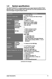
... - Intel® Rapid Storage Technology Enterprise
(RSTe) supports software RAID 0, 1, 10, & 5 (Windows)
4 x Internal...ASUS TS100-E8-PI4
1-3 The server supports Intel® LGA1150 Xeon® E3-1200 v3 processors with the latest technologies through the chipsets onboard.
1.3 System specifications
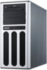
The ASUS TS100-E8-PI4 is a pedestal barebone server system featuring the ASUS P9D-X/ MR server...
User Guide - Page 17
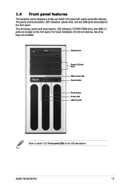
For future installation of 5.25-inch devices, two drive bays are located on the front panel.
The...section 1.7.1 Front panel LEDs for the LED descriptions. ASUS TS100-E8-PI4
1-5 The drive bays, power and reset buttons, LED indicators, CD/DVD-ROM drive, and USB 2.0 ports are available. 1.4 Front panel features
The barebone server displays a simple yet stylish front panel with easily ...
User Guide - Page 19
...use a floppy disk or a optical disc.
*WARNING HAZARDOUS MOVING PARTS KEEP FINGERS AND OTHER BODY PARTS AWAY
ASUS TS100-E8-PI4
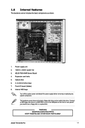
1-7 Front I/O board (hidden) 8. Expansion card locks 5. 1.6 Internal features
The barebone server includes the basic components as shown.
1
2 3
4
5 6
7
8
1. ASUS P9D-X/MR Server Board 4. The barebone server does not include a floppy disk drive and an optical disc...
User Guide - Page 31
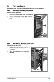
... on the chassis side rail. 2.
Swing the front panel cover and snap it back
into place. ASUS TS100-E8-PI4
2-11 Hook the other side of the front panel cover to
the chassis. 2. 2.4 Front panel cover
Before you can install a 5.25-inch drive, you should first remove the front panel cover.
2.4.1 Removing the front panel...
User Guide - Page 33
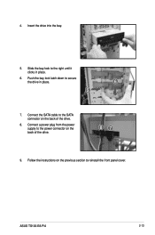
... power supply to the power connector on the back of the drive.
8. Follow the instructions on the back of the drive.
87
9. 4. Insert the drive into the bay.
5. Slide the bay lock to reinstall the front panel cover. ASUS TS100-E8-PI4
2-13 Connect the SATA cable to secure
the drive in place.
6.
Push the...
User Guide - Page 35
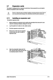
... slot.
6
ASUS TS100-E8-PI4
2-15
Push the expansion card to unplug the power cord before installing or removing expansion cards. Ensure to the left.
5. Failure to do so may cause severe damage to install an expansion card... the necessary hardware settings for you wish to the motherboard and other system components!
2.7.1 Installing an expansion card
To install an expansion card:
1.
User Guide - Page 37
... following tables.
3. Install the software drivers for information on the system and change the necessary BIOS settings, if any. ASUS TS100-E8-PI4
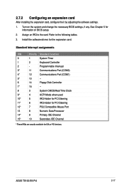
2-17 Refer to the card. 2.7.2 Configuring an expansion card
After installing the expansion card, configure the it by adjusting the software settings.
1.
See Chapter 5 for the expansion card. Turn on BIOS setup.
2. Programmable Interrupt...
User Guide - Page 39

... connector (from motherboard to SATA devices) 5. You do not need to disconnect these cables unless you will remove pre‑installed components to install additional devices.
• Refer to Chapter 3 for detailed information on the connectors.
1 2
3
4
Standard cables connected... conectors (system default; USB connectors (from power supply to front I /O board)
ASUS TS100-E8-PI4
5 6
2-19
User Guide - Page 41
ASUS TS100-E8-PI4 Motherboard Info
Chapter 3
This chapter includes the motherboard layout and brief descriptions of the jumpers and internal connectors.
User Guide - Page 43
...
(24-pin EATXPWR1, 8-pin EATX12V1)
11. Auxiliary panel connector (20-2 pin AUX_PANEL1)
Page 3-7
3-8 3-8 3-9
3-9
3-10 3-10 3-11 3-11 3-12 3-13 3-14
ASUS TS100-E8-PI4
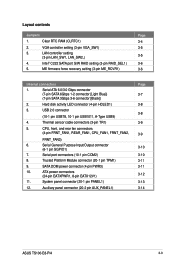
3-3 Layout contents
Jumpers
1. Clear RTC RAM (CLRTC1)
2.
VGA controller setting (3-pin VGA_SW1)
3. Intel® C222 SATA port S/W RAID setting (3-pin RAID_SEL1)
5. Hard disk activity LED connector (4-pin HDLED1)
3.
User Guide - Page 45
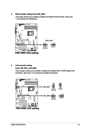
... 1-2 to activate the Gigabit LAN feature. LAN controller setting (3-pin LAN_SW1, LAN_SW2) These jumpers allows you to enable or disable the onboard Intel® I210AT Gigabit LAN controllers. Set to pins 1-2 to activate the VGA feature.
3.
ASUS TS100-E8-PI4
3-5 VGA controller setting (3-pin VGA_SW1) This jumper allows you to enable or disable the onboard VGA controller...
User Guide - Page 47
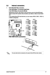
If you installed Serial ATA hard disk drives, you can create a RAID 0, RAID 1, RAID 10, or RAID 5 configuration. The actual data transfer rate depends on the speed of data transfer rate. ASUS TS100-E8-PI4
3-7 Serial ATA 6.0/3.0 Gbps connectors (7-pin SATA 6Gbps_1-2 connector [Light Blue]) (7-pin SATA 3Gbps_3-6 connector [Black]) Supported by the Intel® C222 chipset, these connectors ...
User Guide - Page 49
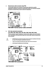
...the fan cables to connect a Thermal sensor cable that you to the fan connectors.
ASUS TS100-E8-PI4
3-9 Thermal sensor cable connectors (3-pin TR1) This connector allows you want to check...All fans feature the ASUS Smart Fan technology. 4. CPU, front, and rear fan connectors (4-pin FRNT_FAN1, REAR_FAN1, CPU_FAN1, FRNT_FAN2, FRNT_FAN3) The fan connectors support cooling fans. Connect ...
User Guide - Page 53

... reset button for the chassis-mounted system warning speaker. Pressing the power switch for the message LED cable that connects to the HDD.
5. 11. System panel connector (20-1 pin PANEL1) This connector supports several chassis-mounted functions.
1. Power button/soft-off mode depending on or puts the system in sleep mode.
2. ASUS TS100-E8-PI4
3-13
Asus TS100-E8-PI4 Reviews
We have not received any reviews for Asus yet.