
User Guide
Page 15
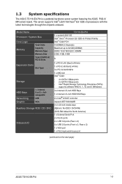
... Storage HDD Bays Networking Graphic I = internal A or S = hotswappable LAN VGA Auxiliary Storage FDD / CD / DVD Onboard I/O TS110-E8-PI4 1 x socket LGA1150 Intel® Xeon® Processor E3-1200 v3 Product Family Intel® C222 PCH 4 UDIMM (2 Channels)...x 2, Rear x 2) 1 x VGA port 1 x PS/2 keyboard/mouse port (continued on the next page) ASUS TS110-E8-PI4 1-3 1.3 System specifications The ASUS TS110-E8-PI4 is a pedestal barebone server system featuring the ASUS P9D-X/ MR server board. The server supports Intel® LGA1150 Xeon® E3-1200 v3 processors with the latest ...
... Storage HDD Bays Networking Graphic I = internal A or S = hotswappable LAN VGA Auxiliary Storage FDD / CD / DVD Onboard I/O TS110-E8-PI4 1 x socket LGA1150 Intel® Xeon® Processor E3-1200 v3 Product Family Intel® C222 PCH 4 UDIMM (2 Channels)...x 2, Rear x 2) 1 x VGA port 1 x PS/2 keyboard/mouse port (continued on the next page) ASUS TS110-E8-PI4 1-3 1.3 System specifications The ASUS TS110-E8-PI4 is a pedestal barebone server system featuring the ASUS P9D-X/ MR server board. The server supports Intel® LGA1150 Xeon® E3-1200 v3 processors with the latest ...
User Guide
Page 17
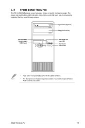
ASUS TS110-E8-PI4 1-5 The power and reset buttons, LED indicators, optical drive, and USB ports are available if you install an optional Add-on Audio card into your ... for the LED descriptions. • The Microphone and Headphone port are all conveniently located at the fron panel for easy access. 1.4 Front panel features The TS110-E8-PI4 Pedestal server features a simple yet stylish front panel design.
ASUS TS110-E8-PI4 1-5 The power and reset buttons, LED indicators, optical drive, and USB ports are available if you install an optional Add-on Audio card into your ... for the LED descriptions. • The Microphone and Headphone port are all conveniently located at the fron panel for easy access. 1.4 Front panel features The TS110-E8-PI4 Pedestal server features a simple yet stylish front panel design.

User Guide
Page 19
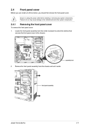
Power supply unit 2. 120 mm x 120 mm system fan 3. Optical drive (Optional) 6. 1 x 5.25-inch drive bay 7. 1.6 Internal features The TS110-E8-PI4 Pedestal server sytem includes the basic components as shown: 1. Front I/O board (hidden) 8. 3 x 3.5-inch Internal HDD bays 9. 1 x 2.5-inch Internal HDD/SSD bay Turn off the ... or replacing any of the USB ports on the front or rear panel. *WARNING HAZARDOUS MOVING PARTS KEEP FINGERS AND OTHER BODY PARTS AWAY ASUS TS110-E8-PI4 1-7 Expansion card locks 5. If you need to use a floppy disk, connect the USB floppy disk drive to any system component...
Power supply unit 2. 120 mm x 120 mm system fan 3. Optical drive (Optional) 6. 1 x 5.25-inch drive bay 7. 1.6 Internal features The TS110-E8-PI4 Pedestal server sytem includes the basic components as shown: 1. Front I/O board (hidden) 8. 3 x 3.5-inch Internal HDD bays 9. 1 x 2.5-inch Internal HDD/SSD bay Turn off the ... or replacing any of the USB ports on the front or rear panel. *WARNING HAZARDOUS MOVING PARTS KEEP FINGERS AND OTHER BODY PARTS AWAY ASUS TS110-E8-PI4 1-7 Expansion card locks 5. If you need to use a floppy disk, connect the USB floppy disk drive to any system component...

User Guide
Page 21
It includes description of the jumpers and connectors on the motherboard. 2 ASUS TS110-E8-PI4 2-1 Chapter 2: Hardware Information Hardware Information This chapter lists the hardware setup procedures that you have to perform when installing system components.
It includes description of the jumpers and connectors on the motherboard. 2 ASUS TS110-E8-PI4 2-1 Chapter 2: Hardware Information Hardware Information This chapter lists the hardware setup procedures that you have to perform when installing system components.

User Guide
Page 23
Remove the cover and set it from the chassis. 4. Slightly pull the side cover toward the rear just enough to detach it aside. ASUS TS110-E8-PI4 2-3 3.
Remove the cover and set it from the chassis. 4. Slightly pull the side cover toward the rear just enough to detach it aside. ASUS TS110-E8-PI4 2-3 3.

User Guide
Page 25
Load lever Retention tab Load plate 4. Gold triangle mark Alignment key CPU notches Alignment key ASUS TS110-E8-PI4 2-5 Press the load lever with your thumb (A), then move it to the right (B) until the load plate is completely lifted. Lift the load lever until ...
Load lever Retention tab Load plate 4. Gold triangle mark Alignment key CPU notches Alignment key ASUS TS110-E8-PI4 2-5 Press the load lever with your thumb (A), then move it to the right (B) until the load plate is completely lifted. Lift the load lever until ...

User Guide
Page 27
2.3.2 Installing the CPU heatsink and fan assembly To install the CPU heatsink and fan assembly ASUS TS110-E8-PI4 2-7
2.3.2 Installing the CPU heatsink and fan assembly To install the CPU heatsink and fan assembly ASUS TS110-E8-PI4 2-7

User Guide
Page 29
The figure illustrates the location of the DDR3 DIMM sockets: 2.3.2 Memory Configurations You may install 2 GB, 4 GB, 8 GB Unbuffered with the same CAS latency. ASUS TS110-E8-PI4 2-9 DIMM Slot Per Channel 2 2 DIMM Populated per Channel 1 2 Memory Configuration DIMM Type Speed Rank per DIMM Unbuffered DDR3 ECC 1333/1600 Single Rank, Dual Rank ...
The figure illustrates the location of the DDR3 DIMM sockets: 2.3.2 Memory Configurations You may install 2 GB, 4 GB, 8 GB Unbuffered with the same CAS latency. ASUS TS110-E8-PI4 2-9 DIMM Slot Per Channel 2 2 DIMM Populated per Channel 1 2 Memory Configuration DIMM Type Speed Rank per DIMM Unbuffered DDR3 ECC 1333/1600 Single Rank, Dual Rank ...
User Guide
Page 31
... cover: 1. Failure to do so may cause damage to unplug the power cable before installing or removing any system components. assembly lock 2. front panel assembly ASUS TS110-E8-PI4 2-11 Remove the front panel assembly from the chassis and set it outward to unlock the latches that secures the front panel cover to the...
... cover: 1. Failure to do so may cause damage to unplug the power cable before installing or removing any system components. assembly lock 2. front panel assembly ASUS TS110-E8-PI4 2-11 Remove the front panel assembly from the chassis and set it outward to unlock the latches that secures the front panel cover to the...
User Guide
Page 33
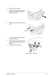
Prepare the 5.25-inch drive. 5. bay locks 7. Connect the SATA cable to the power connector of the drive. 8. Connect a SATA power cable from the power supply to the SATA connector of the drive. 9. SATA power cable SATA cable ASUS TS110-E8-PI4 2-13 Reinstall the front panel cover. Insert and carefully push the drive into the bay until its screw holes align with the holes on the bay. 6. Push the bay locks to secure the drive in place. 4.
Prepare the 5.25-inch drive. 5. bay locks 7. Connect the SATA cable to the power connector of the drive. 8. Connect a SATA power cable from the power supply to the SATA connector of the drive. 9. SATA power cable SATA cable ASUS TS110-E8-PI4 2-13 Reinstall the front panel cover. Insert and carefully push the drive into the bay until its screw holes align with the holes on the bay. 6. Push the bay locks to secure the drive in place. 4.
User Guide
Page 35
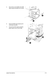
Secure the 3.5-inch HDD to the 3.5-inch HDD. Swing the HDD cage inwards until it clicks back into place. 7. ASUS TS110-E8-PI4 2-15 Connect the SATA cable and SATA power cable to the HDD cage using the bundled set of screws. 6. 5.
Secure the 3.5-inch HDD to the 3.5-inch HDD. Swing the HDD cage inwards until it clicks back into place. 7. ASUS TS110-E8-PI4 2-15 Connect the SATA cable and SATA power cable to the HDD cage using the bundled set of screws. 6. 5.
User Guide
Page 37
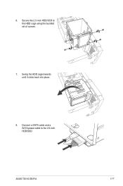
6. Secure the 2.5-inch HDD/SSD to the 2.5-inch HDD/SSD. Connect a SATA cable and a SATA power cable to the HDD cage using the bundled set of screws. 7. ASUS TS110-E8-PI4 2-17 Swing the HDD cage inwards until it clicks back into place. 8.
6. Secure the 2.5-inch HDD/SSD to the 2.5-inch HDD/SSD. Connect a SATA cable and a SATA power cable to the HDD cage using the bundled set of screws. 7. ASUS TS110-E8-PI4 2-17 Swing the HDD cage inwards until it clicks back into place. 8.

User Guide
Page 39
4. PCI-E latch ASUS TS110-E8-PI4 2-19 Align and insert the expansion card into place securing the expansion card to the chassis. 6. (Optional) Replace the screw of the metal bracket. Lift the PCI-E latch inwards until it clicks into the PCI-E slot. expansion card PCI-E slot 5.
4. PCI-E latch ASUS TS110-E8-PI4 2-19 Align and insert the expansion card into place securing the expansion card to the chassis. 6. (Optional) Replace the screw of the metal bracket. Lift the PCI-E latch inwards until it clicks into the PCI-E slot. expansion card PCI-E slot 5.
User Guide
Page 41
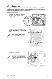
... the screws for later use. Follow the previous instructions in the event that you want to be replaced because it was damaged or became defective. ASUS TS110-E8-PI4 2-21 2.8 System fan This section describes how to remove the system fan in reverse order if you need to install or remove previously installed or...
... the screws for later use. Follow the previous instructions in the event that you want to be replaced because it was damaged or became defective. ASUS TS110-E8-PI4 2-21 2.8 System fan This section describes how to remove the system fan in reverse order if you need to install or remove previously installed or...

User Guide
Page 45
... (6-1 pin SGPIO1) 7. ATX power connectors (24-pin EATXPWR1, 8-pin EATX12V1) 11. Auxiliary panel connector (20-2 pin AUX_PANEL1) Page 3-7 3-8 3-8 3-9 3-9 3-10 3-10 3-11 3-11 3-12 3-13 3-14 ASUS TS110-E8-PI4 3-3 System panel connector (20-1 pin PANEL1) 12. Layout contents Jumpers 1. Intel® C222 SATA port S/W RAID setting (3-pin RAID_SEL1) 5. ME firmware force recovery setting (3-pin...
... (6-1 pin SGPIO1) 7. ATX power connectors (24-pin EATXPWR1, 8-pin EATX12V1) 11. Auxiliary panel connector (20-2 pin AUX_PANEL1) Page 3-7 3-8 3-8 3-9 3-9 3-10 3-10 3-11 3-11 3-12 3-13 3-14 ASUS TS110-E8-PI4 3-3 System panel connector (20-1 pin PANEL1) 12. Layout contents Jumpers 1. Intel® C222 SATA port S/W RAID setting (3-pin RAID_SEL1) 5. ME firmware force recovery setting (3-pin...

User Guide
Page 47
VGA controller setting (3-pin VGA_SW1) This jumper allows you to activate the VGA feature. 3. ASUS TS110-E8-PI4 3-5 2. Set to pins 1-2 to enable or disable the onboard VGA controller. Set to pins 1-2 to enable or disable the onboard Intel® I210AT Gigabit LAN controllers. LAN controller setting (3-pin LAN_SW1, LAN_SW2) These jumpers allows you to activate the Gigabit LAN feature.
VGA controller setting (3-pin VGA_SW1) This jumper allows you to activate the VGA feature. 3. ASUS TS110-E8-PI4 3-5 2. Set to pins 1-2 to enable or disable the onboard VGA controller. Set to pins 1-2 to enable or disable the onboard Intel® I210AT Gigabit LAN controllers. LAN controller setting (3-pin LAN_SW1, LAN_SW2) These jumpers allows you to activate the Gigabit LAN feature.

User Guide
Page 49
ASUS TS110-E8-PI4 3-7 If you installed Serial ATA hard disk drives, you can create a RAID 0, RAID 1, RAID 10, or RAID 5 configuration. Serial ATA 6.0/3.0 Gbps connectors (7-pin SATA 6Gbps_1-2 connector [Light Blue]) (7-pin SATA 3Gbps_3-6 connector [Black]) Supported by the Intel® C222 chipset, these connectors are for the Serial ATA signal cables for Serial ATA hard disk drives that allows up to 6Gb/s or 3Gb/s of Serial ATA hard disks installed. 3.3 Internal connectors 1. The actual data transfer rate depends on the speed of data transfer rate.
ASUS TS110-E8-PI4 3-7 If you installed Serial ATA hard disk drives, you can create a RAID 0, RAID 1, RAID 10, or RAID 5 configuration. Serial ATA 6.0/3.0 Gbps connectors (7-pin SATA 6Gbps_1-2 connector [Light Blue]) (7-pin SATA 3Gbps_3-6 connector [Black]) Supported by the Intel® C222 chipset, these connectors are for the Serial ATA signal cables for Serial ATA hard disk drives that allows up to 6Gb/s or 3Gb/s of Serial ATA hard disks installed. 3.3 Internal connectors 1. The actual data transfer rate depends on the speed of data transfer rate.

User Guide
Page 51
... cable that you to the fan connectors. Connect the fan cables to the fan connectors on the fan connectors! • All fans feature the ASUS Smart Fan technology. ASUS TS110-E8-PI4 3-9 CPU, front, and rear fan connectors (4-pin FRNT_FAN1, REAR_FAN1, CPU_FAN1, FRNT_FAN2, FRNT_FAN3) The fan connectors support cooling fans. Insufficient air flow inside the...
... cable that you to the fan connectors. Connect the fan cables to the fan connectors on the fan connectors! • All fans feature the ASUS Smart Fan technology. ASUS TS110-E8-PI4 3-9 CPU, front, and rear fan connectors (4-pin FRNT_FAN1, REAR_FAN1, CPU_FAN1, FRNT_FAN2, FRNT_FAN3) The fan connectors support cooling fans. Insufficient air flow inside the...

User Guide
Page 53
SATA DOM power connector (4-pin PWR3) This 4-pin connector is for 5V power of certain SATA DOM (Disk on Module) device when using an appropriate cable. ASUS TS110-E8-PI4 3-11 A TPM system also helps enhance network security, protects digital identities, and ensures platform integrity. 9. 8. Trusted Platform Module connector (20-1 pin TPM1) This connector supports a Trusted Platform Module (TPM) system, which can securely store keys, digital certificates, passwords, and data.
SATA DOM power connector (4-pin PWR3) This 4-pin connector is for 5V power of certain SATA DOM (Disk on Module) device when using an appropriate cable. ASUS TS110-E8-PI4 3-11 A TPM system also helps enhance network security, protects digital identities, and ensures platform integrity. 9. 8. Trusted Platform Module connector (20-1 pin TPM1) This connector supports a Trusted Platform Module (TPM) system, which can securely store keys, digital certificates, passwords, and data.

User Guide
Page 55
... abnormal event occurance. 3. Pressing the power switch for more than four seconds while the system is controlled by Hardware monitor to the front message LED. ASUS TS110-E8-PI4 3-13
... abnormal event occurance. 3. Pressing the power switch for more than four seconds while the system is controlled by Hardware monitor to the front message LED. ASUS TS110-E8-PI4 3-13


