
User Guide
Page 3
... expansion card to the riser card bracket....2-11 2.5.2 Configuring an expansion card 2-12 2.6 Cable connections 2-13 2.7 Removable/optional components 2-14 2.7.1 Replacing system fans 2-14 2.7.2 Replacing power supply units 2-15 2.7.3 Installing ASMB4 series management board (optional) 2-16 2.7.4 Installing ASUS PIKE Riser Card (optional 2-17 iii
... expansion card to the riser card bracket....2-11 2.5.2 Configuring an expansion card 2-12 2.6 Cable connections 2-13 2.7 Removable/optional components 2-14 2.7.1 Replacing system fans 2-14 2.7.2 Replacing power supply units 2-15 2.7.3 Installing ASMB4 series management board (optional) 2-16 2.7.4 Installing ASUS PIKE Riser Card (optional 2-17 iii

User Guide
Page 8
... technician or your dealer. If possible, disconnect all cables are correctly connected and the power cables are unplugged. • To prevent electrical shock hazard, disconnect the power cable from the electrical outlet before you service. • If the power supply is to be performed by trained service personnel only. • Before operating the server...
... technician or your dealer. If possible, disconnect all cables are correctly connected and the power cables are unplugged. • To prevent electrical shock hazard, disconnect the power cable from the electrical outlet before you service. • If the power supply is to be performed by trained service personnel only. • Before operating the server...
User Guide
Page 12
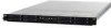
... Riser Card (ASUS RE16R-R12B) 2 x Front I/O Board (ASUS FPB-AR14) 1 x Power Distribution Board (ASUS PDB-R12B) 8 x System Fans (40mm x 56mm) 2 x 770W Single Power Supply 8 x Hot-swap 2.5" HDD trays 1 x SAS/SATA2 Backplane 2 x PCI Riser Card (ASUS RE16R-R12B) 2 x Front I/O Board (ASUS FPB-R12A) 1 x Power Distribution Board (ASUS PDB-R12B) 8 x System Fans (40mm x 56mm) Accessories 1 x RS700D-E6/PS8, RS702D-E6/PS8, RS704D-E6/PS8 User's Guide 1 x ASUS ASWM 2.0 User's Guide...
... Riser Card (ASUS RE16R-R12B) 2 x Front I/O Board (ASUS FPB-AR14) 1 x Power Distribution Board (ASUS PDB-R12B) 8 x System Fans (40mm x 56mm) 2 x 770W Single Power Supply 8 x Hot-swap 2.5" HDD trays 1 x SAS/SATA2 Backplane 2 x PCI Riser Card (ASUS RE16R-R12B) 2 x Front I/O Board (ASUS FPB-R12A) 1 x Power Distribution Board (ASUS PDB-R12B) 8 x System Fans (40mm x 56mm) Accessories 1 x RS700D-E6/PS8, RS702D-E6/PS8, RS704D-E6/PS8 User's Guide 1 x ASUS ASWM 2.0 User's Guide...
User Guide
Page 15
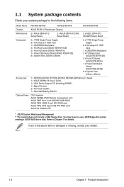
ASUS RS700D-E6/PS8, RS702D-E6/PS8, RS704D-E6/PS8 1-5 Model Name RS700D-E6/PS8 RS702D-E6/PS8 RS704D-E6/PS8 Graphic VGA Aspeed AST2050 8MB Onboard I/O OS Support Per Node: Per Node: - 1 x External Serial - 1 x External Serial Port Port - 3 x RJ-45 ports (1 - 3 x RJ-45 ports ... Remote Hardware Software Optional ASMB4-iKVM for KVM-over-IP support ASUS ASWM 2.0® Dimension (HH x WW x DD) 686mm x 444mm x 43.4mm Net Weight Kg (CPU, DRAM & HDD not inclu ded) 18 Kg Power Supply 770W (80+) Cold-Swap Power Supply per Node Power Rating Input: 100-127/200-240V, 9.55/4.8A, 50-60Hz...
ASUS RS700D-E6/PS8, RS702D-E6/PS8, RS704D-E6/PS8 1-5 Model Name RS700D-E6/PS8 RS702D-E6/PS8 RS704D-E6/PS8 Graphic VGA Aspeed AST2050 8MB Onboard I/O OS Support Per Node: Per Node: - 1 x External Serial - 1 x External Serial Port Port - 3 x RJ-45 ports (1 - 3 x RJ-45 ports ... Remote Hardware Software Optional ASMB4-iKVM for KVM-over-IP support ASUS ASWM 2.0® Dimension (HH x WW x DD) 686mm x 444mm x 43.4mm Net Weight Kg (CPU, DRAM & HDD not inclu ded) 18 Kg Power Supply 770W (80+) Cold-Swap Power Supply per Node Power Rating Input: 100-127/200-240V, 9.55/4.8A, 50-60Hz...

User Guide
Page 16
... LED LAN2 LED HDD Access LED Hot-swap HDD bays Rack screw Hot-swap HDD bays Power button Reset button Location switch USB port Hot-swap HDD bays Turn off the system power and detach the power supply before removing or replacing any system component. 1-6 Chapter 1: Product introduction 1.4 Front panel features The barebone server...
... LED LAN2 LED HDD Access LED Hot-swap HDD bays Rack screw Hot-swap HDD bays Power button Reset button Location switch USB port Hot-swap HDD bays Turn off the system power and detach the power supply before removing or replacing any system component. 1-6 Chapter 1: Product introduction 1.4 Front panel features The barebone server...

User Guide
Page 17
... 2 LAN port 1 USB ports LAN port* Power cord connector Power supply fan Power cord connector Power supply fan Serial port Location LED InfiniBand port VGA port LAN port 2 LAN port 1 USB ports LAN port* * These ports are not present. Ready Device plugged in ; Data transmitting ACT LED LINK LED ASUS RS700D-E6/PS8, RS702D-E6/PS8, RS704D-E6/PS8 1-7 Infiniband (MQSFP1) indications Activity LED...
... 2 LAN port 1 USB ports LAN port* Power cord connector Power supply fan Power cord connector Power supply fan Serial port Location LED InfiniBand port VGA port LAN port 2 LAN port 1 USB ports LAN port* * These ports are not present. Ready Device plugged in ; Data transmitting ACT LED LINK LED ASUS RS700D-E6/PS8, RS702D-E6/PS8, RS704D-E6/PS8 1-7 Infiniband (MQSFP1) indications Activity LED...

User Guide
Page 18
...optical disc drive. Hot-swap HDD tray 1 and 3-Connect to SATA2 and SATA4 ports 8. Power supplies and power fans 2. Front I/O boards (hidden) Turn off the system power and detach the power supply before removing or replacing any of the USB ports on the front or rear panel if ...slot Riser Cards (at x16 link) 3. RS700D-E6/PS4, RS702D-E6/PS4 2 2 11 3 3 4 5 67 89 10 10 1. 1.6 Internal features The barebone server includes the basic components as shown. ASUS Z8PH-D12/IFB server boards (RS702D-E6/PS4) 4. ASUS Z8NH-D12 server boards (RS700D-E6/PS4); Hot-swap HDD tray 2 and ...
...optical disc drive. Hot-swap HDD tray 1 and 3-Connect to SATA2 and SATA4 ports 8. Power supplies and power fans 2. Front I/O boards (hidden) Turn off the system power and detach the power supply before removing or replacing any of the USB ports on the front or rear panel if ...slot Riser Cards (at x16 link) 3. RS700D-E6/PS4, RS702D-E6/PS4 2 2 11 3 3 4 5 67 89 10 10 1. 1.6 Internal features The barebone server includes the basic components as shown. ASUS Z8PH-D12/IFB server boards (RS702D-E6/PS4) 4. ASUS Z8NH-D12 server boards (RS700D-E6/PS4); Hot-swap HDD tray 2 and ...

User Guide
Page 19
... KEEP FINGERS AND OTHER BODY PARTS AWAY ASUS RS700D-E6/PS8, RS702D-E6/PS8, RS704D-E6/PS8 1-9 HDD tray 2 and 4-Connect to SATA2 and SATA4 ports 10. HDD tray 1 and 3-Connect to SATA1 and SATA3 ports 7. ASUS Z8PH-D12 SE/QDR server boards 4. Front I/O boards (hidden) Turn off the system power and detach the power supply before removing or replacing any of...
... KEEP FINGERS AND OTHER BODY PARTS AWAY ASUS RS700D-E6/PS8, RS702D-E6/PS8, RS704D-E6/PS8 1-9 HDD tray 2 and 4-Connect to SATA2 and SATA4 ports 10. HDD tray 1 and 3-Connect to SATA1 and SATA3 ports 7. ASUS Z8PH-D12 SE/QDR server boards 4. Front I/O boards (hidden) Turn off the system power and detach the power supply before removing or replacing any of...

User Guide
Page 29
... to unplug the power supply before adding or removing DIMMs or other system components. Align a DIMM on the socket such that the notch on the DIMM matches the break on the socket. 2 DIMM notch 1 1 Unlocked retaining clip A DIMM is properly seated. Remove the DIMM from the socket. ASUS RS700D-E6/PS8, RS702D-E6/PS8, RS704D-E6/PS8 2-9 Firmly insert the...
... to unplug the power supply before adding or removing DIMMs or other system components. Align a DIMM on the socket such that the notch on the DIMM matches the break on the socket. 2 DIMM notch 1 1 Unlocked retaining clip A DIMM is properly seated. Remove the DIMM from the socket. ASUS RS700D-E6/PS8, RS702D-E6/PS8, RS704D-E6/PS8 2-9 Firmly insert the...

User Guide
Page 33
... to install additional devices. • Refer to Chapter 4 for detailed information on the connectors. 6 6 57 57 2 2 3 34 1 3 34 1 3 3 3 3 Pre-connected system cables 1. 20-pin proprietary power connector (from power supply to motherboard) 2. 4-pin proprietary power connector (from motherboard to motherboard) 3. Panel connector (from power supply to front I /O board) ASUS RS700D-E6/PS8, RS702D-E6/PS8, RS704D-E6/PS8 2-13
... to install additional devices. • Refer to Chapter 4 for detailed information on the connectors. 6 6 57 57 2 2 3 34 1 3 34 1 3 3 3 3 Pre-connected system cables 1. 20-pin proprietary power connector (from power supply to motherboard) 2. 4-pin proprietary power connector (from motherboard to motherboard) 3. Panel connector (from power supply to front I /O board) ASUS RS700D-E6/PS8, RS702D-E6/PS8, RS704D-E6/PS8 2-13

User Guide
Page 34
ASUS ASMB4-iKVM (optional) 4 ASUS PIKE Riser card (optional) Ensure that the system is turned off before removing any components. 2.7.1 Replacing system fans To uninstall the system fans: 1. Repeat step 1 ... point towards the system rear panel. 2. The airflow directional arrow on the motherboard. 2. Or you may need to install the optional components into the system. Power supply units 3. Insert the fan to the fan connector on the motherboard. 2-14 Chapter 2: Hardware setup 2.7 Removable/optional components You may need to remove previously installed...
ASUS ASMB4-iKVM (optional) 4 ASUS PIKE Riser card (optional) Ensure that the system is turned off before removing any components. 2.7.1 Replacing system fans To uninstall the system fans: 1. Repeat step 1 ... point towards the system rear panel. 2. The airflow directional arrow on the motherboard. 2. Or you may need to install the optional components into the system. Power supply units 3. Insert the fan to the fan connector on the motherboard. 2-14 Chapter 2: Hardware setup 2.7 Removable/optional components You may need to remove previously installed...

User Guide
Page 35
Firmly pull the failed PSU out of the server chassis. 3. To replace the failed PSU 1. ASUS RS700D-E6/PS8, RS702D-E6/PS8, RS704D-E6/PS8 2-15 Press down gently on the location above the system fans to ensure proper fan installation, as shown in the right figure. 2.7.2 Replacing power supply units Follow the steps below to the server chassis. Firmly push the new PSU into the chassis until the latch locks to replace the failed power supply unit (PSU). Recover the rear cover. Hold the PSU lever and press the PSU latch. 2. 3.
Firmly pull the failed PSU out of the server chassis. 3. To replace the failed PSU 1. ASUS RS700D-E6/PS8, RS702D-E6/PS8, RS704D-E6/PS8 2-15 Press down gently on the location above the system fans to ensure proper fan installation, as shown in the right figure. 2.7.2 Replacing power supply units Follow the steps below to the server chassis. Firmly push the new PSU into the chassis until the latch locks to replace the failed power supply unit (PSU). Recover the rear cover. Hold the PSU lever and press the PSU latch. 2. 3.

User Guide
Page 49
... (4-pin LVDDR3_SEL1, LVDDR3_SEL2) 4. CPU warning LED (ERR_CPU1, ERR_CPU2) Page 4-20 4-20 ASUS RS700D-E6/PS8, RS702D-E6/PS8, RS704D-E6/PS8 4-5 Clear RTC RAM (CLRTC1) 2. A-Type USB4) 3. Standby power LED 2. Serial General Purpose Input/Output connector (6-1 pin SGPIO1) 6. Auxiliary panel connector (... (3-pin RECOVERY1) Page 4-6 4-7 4-8 4-9 4-10 4-11 Internal connectors 1. Power Supply SMBus connectors (6-1 pin JP1, JP2) 8. Intel ICH10R® SATA ports S/W RAID setting (3-pin RAID_SEL1) 6. Proprietary power connectors (20-pin PWR1, 20-pin PWR2, 4-pin PWR3) 9. VGA controller...
... (4-pin LVDDR3_SEL1, LVDDR3_SEL2) 4. CPU warning LED (ERR_CPU1, ERR_CPU2) Page 4-20 4-20 ASUS RS700D-E6/PS8, RS702D-E6/PS8, RS704D-E6/PS8 4-5 Clear RTC RAM (CLRTC1) 2. A-Type USB4) 3. Standby power LED 2. Serial General Purpose Input/Output connector (6-1 pin SGPIO1) 6. Auxiliary panel connector (... (3-pin RECOVERY1) Page 4-6 4-7 4-8 4-9 4-10 4-11 Internal connectors 1. Power Supply SMBus connectors (6-1 pin JP1, JP2) 8. Intel ICH10R® SATA ports S/W RAID setting (3-pin RAID_SEL1) 6. Proprietary power connectors (20-pin PWR1, 20-pin PWR2, 4-pin PWR3) 9. VGA controller...

User Guide
Page 60
6. Devices communicate with an SMBus host and/or other SMBus devices using the SMBus interface. 4-16 Chapter 4: Motherboard information BMC header (BMC_FW1) The BMC connector on the motherboard supports an ASUS® Server Management Board 4 Series (ASMB4). 7. Power Supply SMBus connectors (6-1 pin JP1, JP2) These connectors allow you to connect SMBus (System Management Bus) to the power supply unit to read PSU information.
6. Devices communicate with an SMBus host and/or other SMBus devices using the SMBus interface. 4-16 Chapter 4: Motherboard information BMC header (BMC_FW1) The BMC connector on the motherboard supports an ASUS® Server Management Board 4 Series (ASMB4). 7. Power Supply SMBus connectors (6-1 pin JP1, JP2) These connectors allow you to connect SMBus (System Management Bus) to the power supply unit to read PSU information.

User Guide
Page 61
... devices. The 4-pin EZ_PLUG is recommended when configuring a system with a higher power output is designed for Proprietary power supply plugs. The power supply plugs are for hard disk drives power supply. Orient the connectors and push down firmly until they completely fit. ASUS RS700D-E6/PS8, RS702D-E6/PS8, RS704D-E6/PS8 4-17 The system may become unstable or may not boot up the system...
... devices. The 4-pin EZ_PLUG is recommended when configuring a system with a higher power output is designed for Proprietary power supply plugs. The power supply plugs are for hard disk drives power supply. Orient the connectors and push down firmly until they completely fit. ASUS RS700D-E6/PS8, RS702D-E6/PS8, RS704D-E6/PS8 4-17 The system may become unstable or may not boot up the system...


