
User Manual
Page 13
... Hz Dimensions 663 mm (l) x 444 mm (w) x 43.6 mm (h) ASUS RS161-E2/PA2 1-3 1.2 System specifications The ASUS RS161-E2 (PA2) is a 1U barebone server system featuring the ASUS K8N-DRE motherboard. The server supports dual 940-pin AMD Opteron™ 64 processors, and ...includes the latest technologies through the chipsets embedded on this motherboard due to 4 GB DDR availability) LAN 2 x Broadcom® BCM5721 Gigabit PCI-E LAN controllers VGA ATI RAGE-XL PCI-based VGA controller with 8 MB...
... Hz Dimensions 663 mm (l) x 444 mm (w) x 43.6 mm (h) ASUS RS161-E2/PA2 1-3 1.2 System specifications The ASUS RS161-E2 (PA2) is a 1U barebone server system featuring the ASUS K8N-DRE motherboard. The server supports dual 940-pin AMD Opteron™ 64 processors, and ...includes the latest technologies through the chipsets embedded on this motherboard due to 4 GB DDR availability) LAN 2 x Broadcom® BCM5721 Gigabit PCI-E LAN controllers VGA ATI RAGE-XL PCI-based VGA controller with 8 MB...
User Manual
Page 15
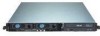
Power fans 4 3. Power supply 5. Hot-swap HDD tray 2 10. ASUS K8N-DRE motherboard 3 4. Front I/O board (hidden) 7 11. Device fans (x 3) 6. Optical drive 8 9 11 10 The barebone server does not include a floppy disk drive. ASUS RS161-E2/PA2 1-5 Hot-swap HDD tray 1 5 9. Connect an external floppy disk drive (USB interface) to any of the USB ports on the front...
Power fans 4 3. Power supply 5. Hot-swap HDD tray 2 10. ASUS K8N-DRE motherboard 3 4. Front I/O board (hidden) 7 11. Device fans (x 3) 6. Optical drive 8 9 11 10 The barebone server does not include a floppy disk drive. ASUS RS161-E2/PA2 1-5 Hot-swap HDD tray 1 5 9. Connect an external floppy disk drive (USB interface) to any of the USB ports on the front...

User Manual
Page 21
2.3 Central Processing Unit (CPU) 2.3.1 Overview The motherboard comes with only 32-bit or 64-bit wide data paths. Take note of these processors can run applications faster than processors with dual surface ... installing only one CPU, use the CPU socket marked CPU1. Locate the CPU socket on the socket to ensure correct installation. ASUS RS161-E2/PA2 2-5 This corner should match a specific corner on the motherboard. Notched corner 2.3.2 Installing the CPU To install a CPU: 1. The 128-bit-wide data paths of the notched corner on the CPU...
2.3 Central Processing Unit (CPU) 2.3.1 Overview The motherboard comes with only 32-bit or 64-bit wide data paths. Take note of these processors can run applications faster than processors with dual surface ... installing only one CPU, use the CPU socket marked CPU1. Locate the CPU socket on the socket to ensure correct installation. ASUS RS161-E2/PA2 2-5 This corner should match a specific corner on the motherboard. Notched corner 2.3.2 Installing the CPU To install a CPU: 1. The 128-bit-wide data paths of the notched corner on the CPU...

User Manual
Page 25
2.4 System memory 2.4.1 Overview The motherboard comes with eight 184-pin Double Data Rate (DDR) Dual Inline Memory Modules (DIMM) sockets. The following figure illustrates the location of the sockets: K8N-DRE ¤ DIMM_A1 DIMM_A2 DIMM_B1 DIMM_B2 DIMM_D2 DIMM_D1 DIMM_C2 DIMM_C1 104 Pins 80 Pins 80 Pins 104 Pins K8N-DRE 184-pin DDR DIMM sockets For CPU 1 Channel A Channel B For CPU 2 Channel A Channel B Sockets DIMM_A1 and DIMM_A2 DIMM_B1 and DIMM_B2 Sockets DIMM_C1 and DIMM_C2 DIMM_D1 and DIMM_D2 ASUS RS161-E2/PA2 2-9
2.4 System memory 2.4.1 Overview The motherboard comes with eight 184-pin Double Data Rate (DDR) Dual Inline Memory Modules (DIMM) sockets. The following figure illustrates the location of the sockets: K8N-DRE ¤ DIMM_A1 DIMM_A2 DIMM_B1 DIMM_B2 DIMM_D2 DIMM_D1 DIMM_C2 DIMM_C1 104 Pins 80 Pins 80 Pins 104 Pins K8N-DRE 184-pin DDR DIMM sockets For CPU 1 Channel A Channel B For CPU 2 Channel A Channel B Sockets DIMM_A1 and DIMM_A2 DIMM_B1 and DIMM_B2 Sockets DIMM_C1 and DIMM_C2 DIMM_D1 and DIMM_D2 ASUS RS161-E2/PA2 2-9
User Manual
Page 31
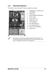
... secure the card with the card into the PCI Express x16 slot on the motherboard. 3. Install the riser card bracket with the screw you removed earlier. 2.6.2 Reinstalling the riser card bracket To reinstall the riser card bracket: 1. ASUS RS161-E2/PA2 2-15 Press the riser card bracket until the golden connectors completely fit the slot...
... secure the card with the card into the PCI Express x16 slot on the motherboard. 3. Install the riser card bracket with the screw you removed earlier. 2.6.2 Reinstalling the riser card bracket To reinstall the riser card bracket: 1. ASUS RS161-E2/PA2 2-15 Press the riser card bracket until the golden connectors completely fit the slot...
User Manual
Page 33
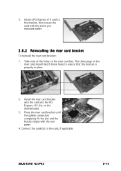
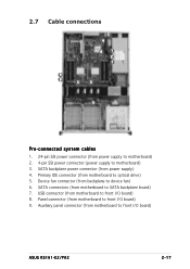
... front I/O board) 9. Panel connector (from motherboard to SATA backplane board) 7. Auxiliary panel connector (from motherboard to optical drive) 5. Primary IDE connector (from motherboard to front I /O board) 8. Device fan connector (from backplane to motherboard) 3. SATA backplane power connector (from motherboard to front I /O board) ASUS RS161-E2/PA2 2-17 2.7 Cable connections 4 6 1 2 7 9 8 5 5 3 Pre-connected system cables 1. 24-pin SSI power connector (from...
... front I/O board) 9. Panel connector (from motherboard to SATA backplane board) 7. Auxiliary panel connector (from motherboard to optical drive) 5. Primary IDE connector (from motherboard to front I /O board) 8. Device fan connector (from backplane to motherboard) 3. SATA backplane power connector (from motherboard to front I /O board) ASUS RS161-E2/PA2 2-17 2.7 Cable connections 4 6 1 2 7 9 8 5 5 3 Pre-connected system cables 1. 24-pin SSI power connector (from...
User Manual
Page 35
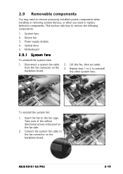
... side. 2. Repeat step 1 to 2 to replace defective components. Take note of the airflow directional arrows embossed on the backplane board. 2. ASUS RS161-E2/PA2 2-19 This section tells how to the fan cage. System fans 2. Motherboard 2.9.1 System fans To uninstall the system fans: 1. Lift the fan, then set aside. 3. To reinstall the system fan: 1. Insert...
... side. 2. Repeat step 1 to 2 to replace defective components. Take note of the airflow directional arrows embossed on the backplane board. 2. ASUS RS161-E2/PA2 2-19 This section tells how to the fan cage. System fans 2. Motherboard 2.9.1 System fans To uninstall the system fans: 1. Lift the fan, then set aside. 3. To reinstall the system fan: 1. Insert...
User Manual
Page 41
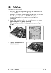
Use a Phillips (cross) screwdriver to remove the screws that secure the motherboard to the base of the chassis. K8N-DRE ¤ 4. 2.9.6 Motherboard To uninstall the motherboard: 1. Disconnect all the devices from the motherboard. ASUS RS161-E2/PA2 2-25 Uninstall all the pre-connected cables from the motherboard including the CPU and heatsink, riser card bracket, and DDR DIMMs. Refer to...
Use a Phillips (cross) screwdriver to remove the screws that secure the motherboard to the base of the chassis. K8N-DRE ¤ 4. 2.9.6 Motherboard To uninstall the motherboard: 1. Disconnect all the devices from the motherboard. ASUS RS161-E2/PA2 2-25 Uninstall all the pre-connected cables from the motherboard including the CPU and heatsink, riser card bracket, and DDR DIMMs. Refer to...

User Manual
Page 47
This chapter includes the motherboard layout, jumper settings, and connector locations ASUS RS161-E2/PA2 2-1 Motherboard info Chapter 4 This chapter gives information about the motherboard that comes with the server.
This chapter includes the motherboard layout, jumper settings, and connector locations ASUS RS161-E2/PA2 2-1 Motherboard info Chapter 4 This chapter gives information about the motherboard that comes with the server.

User Manual
Page 57
... max.) or a total of 1A~3.48A (41.76 W max.) at +12V. DO NOT place jumper caps on the motherboard, making sure that the black wire of each cable matches the ground pin of sufficient air flow inside the system may damage the...motherboard components. K8N-DRE REAR_FAN1 REAR_FAN2 REAR_FAN3 REAR_FAN4 Rotation +12V GND Rotation +12V GND Rotation +12V GND Rotation +12V GND ¤ K8N-DRE Fan connectors FRNT_FAN2 Rotation +12V GND FRNT_FAN6 Rotation +12V GND FRNT_FAN1 FRNT_FAN3 FRNT_FAN4 FRNT_FAN5 Rotation +12V GND Rotation +12V GND Rotation +12V GND Rotation +12V GND ASUS RS161-E2 (PA2...
... max.) or a total of 1A~3.48A (41.76 W max.) at +12V. DO NOT place jumper caps on the motherboard, making sure that the black wire of each cable matches the ground pin of sufficient air flow inside the system may damage the...motherboard components. K8N-DRE REAR_FAN1 REAR_FAN2 REAR_FAN3 REAR_FAN4 Rotation +12V GND Rotation +12V GND Rotation +12V GND Rotation +12V GND ¤ K8N-DRE Fan connectors FRNT_FAN2 Rotation +12V GND FRNT_FAN6 Rotation +12V GND FRNT_FAN1 FRNT_FAN3 FRNT_FAN4 FRNT_FAN5 Rotation +12V GND Rotation +12V GND Rotation +12V GND Rotation +12V GND ASUS RS161-E2 (PA2...

User Manual
Page 65
...copy the current BIOS file using a bootable floppy disk with the updated BIOS file. Copy the AFUDOS utility (afudos.exe) from the motherboard support CD to the bootable floppy disk you can use as shown. 1. A:\>afudos /oOLDBIOS1.rom Main filename Extension name 3. done ...is any user-assigned filename not more than eight alphanumeric characters for the main filename and three alphanumeric characters for reference only. Press . ASUS RS161-E2/PA2 5-3 A:\>afudos /oOLDBIOS1.rom AMI Firmware Update Utility - 5.1.2 AFUDOS utility The AFUDOS utility allows you to update the BIOS file in DOS...
...copy the current BIOS file using a bootable floppy disk with the updated BIOS file. Copy the AFUDOS utility (afudos.exe) from the motherboard support CD to the bootable floppy disk you can use as shown. 1. A:\>afudos /oOLDBIOS1.rom Main filename Extension name 3. done ...is any user-assigned filename not more than eight alphanumeric characters for the main filename and three alphanumeric characters for reference only. Press . ASUS RS161-E2/PA2 5-3 A:\>afudos /oOLDBIOS1.rom AMI Firmware Update Utility - 5.1.2 AFUDOS utility The AFUDOS utility allows you to update the BIOS file in DOS...

User Manual
Page 69
Starting BIOS recovery... When no floppy disk is found, the utility automatically checks the optical drive for this motherboard. The utility then updates the corrupted BIOS file. Floppy not found ! Reading file "K8NDRE.ROM". Starting BIOS recovery... The ... Checking for floppy... CD-ROM found ! Bad BIOS checksum. Doing so can cause system boot failure! 4. Visit the ASUS website (www.asus.com) to the optical drive. 3. ASUS RS161-E2/PA2 5-7 Restart the system after the utility completes the updating process. Insert the support CD to download the latest BIOS file....
Starting BIOS recovery... When no floppy disk is found, the utility automatically checks the optical drive for this motherboard. The utility then updates the corrupted BIOS file. Floppy not found ! Reading file "K8NDRE.ROM". Starting BIOS recovery... The ... Checking for floppy... CD-ROM found ! Bad BIOS checksum. Doing so can cause system boot failure! 4. Visit the ASUS website (www.asus.com) to the optical drive. 3. ASUS RS161-E2/PA2 5-7 Restart the system after the utility completes the updating process. Insert the support CD to download the latest BIOS file....

User Manual
Page 73
...run this last option only if the first two failed. If you with its test routines. ASUS RS161-E2/PA2 5-11 This section explains how to configure your system using this motherboard apply for most conditions to download the latest BIOS file for reference purposes only, and may... a d S e t u p D e f a u l t s item under the Exit Menu. 5.2 BIOS setup program This motherboard supports a programmable firmware chip that the computer can recognize these changes and record them in the CMOS RAM. Use the BIOS Setup program when you are not prompted to "Run Setup." Even if you are for this...
...run this last option only if the first two failed. If you with its test routines. ASUS RS161-E2/PA2 5-11 This section explains how to configure your system using this motherboard apply for most conditions to download the latest BIOS file for reference purposes only, and may... a d S e t u p D e f a u l t s item under the Exit Menu. 5.2 BIOS setup program This motherboard supports a programmable firmware chip that the computer can recognize these changes and record them in the CMOS RAM. Use the BIOS Setup program when you are not prompted to "Run Setup." Even if you are for this...

User Manual
Page 105
...the IDE and/or SATA connectors supported by the NVIDIA® nForce Professional 2200 chip. Connect a SATA power cable to the power connector on the motherboard. 3. To install the SATA hard disks for RAID configuration: 1. For optimal performance, install identical drives of each RAID controller. For example, you...the signal connector at the back of the same model and capacity when creating a disk array. 6.1.2 Installing hard disk drives The motherboard supports Serial ATA hard disk drives for RAID set using the utility embedded in the system user guide. 2. ASUS RS161-E2/PA2 6-3
...the IDE and/or SATA connectors supported by the NVIDIA® nForce Professional 2200 chip. Connect a SATA power cable to the power connector on the motherboard. 3. To install the SATA hard disks for RAID configuration: 1. For optimal performance, install identical drives of each RAID controller. For example, you...the signal connector at the back of the same model and capacity when creating a disk array. 6.1.2 Installing hard disk drives The motherboard supports Serial ATA hard disk drives for RAID set using the utility embedded in the system user guide. 2. ASUS RS161-E2/PA2 6-3

User Manual
Page 117
... disk drive. When the D r i v e r s menu appears, click N V I D I A n F o r c e ( T M ) R A I D D r i v e r D i s k to install the RAID drivers. Follow screen instructions to create an nVIDIA nForce RAID driver disk. Place the motherboard support CD in Windows®: 1. Press , then insert the RAID driver disk to the floppy disk. ASUS RS161-E2/PA2 7-3
... disk drive. When the D r i v e r s menu appears, click N V I D I A n F o r c e ( T M ) R A I D D r i v e r D i s k to install the RAID drivers. Follow screen instructions to create an nVIDIA nForce RAID driver disk. Place the motherboard support CD in Windows®: 1. Press , then insert the RAID driver disk to the floppy disk. ASUS RS161-E2/PA2 7-3
User Manual
Page 119
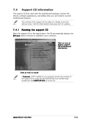
... in your computer. Click an icon to display support CD/motherboard information Click an item to change at any time without notice. Double-click the A S S E T U P . Visit the ASUS website (www.asus.com) for updates. 7.4.1 Running the support CD Place the...motherboard features. 7.4 Support CD information The support CD that came with the motherboard package contains the drivers, software applications, and utilities that you can install to the optical drive. The contents of the support CD to run the CD. E X E to locate the file ASSETUP.EXE from the BIN folder. ASUS RS161-E2/PA2...
... in your computer. Click an icon to display support CD/motherboard information Click an item to change at any time without notice. Double-click the A S S E T U P . Visit the ASUS website (www.asus.com) for updates. 7.4.1 Running the support CD Place the...motherboard features. 7.4 Support CD information The support CD that came with the motherboard package contains the drivers, software applications, and utilities that you can install to the optical drive. The contents of the support CD to run the CD. E X E to locate the file ASSETUP.EXE from the BIN folder. ASUS RS161-E2/PA2...

User Manual
Page 123
Reference information Appendix This appendix includes additional information that you may refer to when configuring the motherboard. ASUS RS161-E2/PA2
Reference information Appendix This appendix includes additional information that you may refer to when configuring the motherboard. ASUS RS161-E2/PA2


