User Guide
Page 4
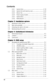
... 4-2 4.2 Jumpers 4-4 4.3 Connectors 4-9 Chapter 5: BIOS setup 5.1 Managing and updating your BIOS 5-2 5.1.1 Creating a bootable floppy disk 5-2 5.1.2 AFUDOS utility 5-3 5.1.3 ASUS CrashFree BIOS 2 utility 5-6 5.1.4 ASUS Update utility 5-8 5.2 BIOS setup program 5-11 5.2.1 BIOS menu screen 5-12 5.2.2 Menu bar 5-12 5.2.3 Navigation keys 5-12 5.2.4 Menu items 5-13 5.2.5 Sub-menu items 5-13 5.2.6 Configuration fields 5-13 5.2.7 Pop-up window 5-13 5.2.8 Scroll bar...
... 4-2 4.2 Jumpers 4-4 4.3 Connectors 4-9 Chapter 5: BIOS setup 5.1 Managing and updating your BIOS 5-2 5.1.1 Creating a bootable floppy disk 5-2 5.1.2 AFUDOS utility 5-3 5.1.3 ASUS CrashFree BIOS 2 utility 5-6 5.1.4 ASUS Update utility 5-8 5.2 BIOS setup program 5-11 5.2.1 BIOS menu screen 5-12 5.2.2 Menu bar 5-12 5.2.3 Navigation keys 5-12 5.2.4 Menu items 5-13 5.2.5 Sub-menu items 5-13 5.2.6 Configuration fields 5-13 5.2.7 Pop-up window 5-13 5.2.8 Scroll bar...
User Guide
Page 10
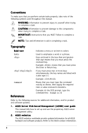
... (+). If you MUST follow to complete a task. Refer to emphasize a word or a phrase. Used to the ASUS contact information. ASUS Server Web-based Management (ASWM) user guide This manual tells how to aid in brackets. Keys enclosed in the less-than and greaterthan sign means that you must type the command exactly as...
... (+). If you MUST follow to complete a task. Refer to emphasize a word or a phrase. Used to the ASUS contact information. ASUS Server Web-based Management (ASWM) user guide This manual tells how to aid in brackets. Keys enclosed in the less-than and greaterthan sign means that you must type the command exactly as...
User Guide
Page 22
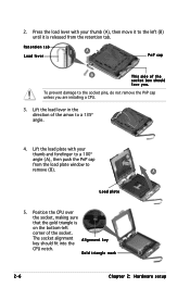
Lift the load lever in the direction of the arrow to the socket pins, do not remove the PnP cap unless you . The socket alignment A l i g n m e n t k e y key should face you are installing a CPU. 3. Press the load lever with your thumb (A), then move it to the left (B) until it is on the bottom-...
Lift the load lever in the direction of the arrow to the socket pins, do not remove the PnP cap unless you . The socket alignment A l i g n m e n t k e y key should face you are installing a CPU. 3. Press the load lever with your thumb (A), then move it to the left (B) until it is on the bottom-...
User Guide
Page 26
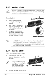
... DIMM might get damaged when it fits in place and the DIMM is properly seated. 2 3 DDR2 DIMM notch Unlocked retaining clip • A DDR2 DIMM is keyed with your fingers when pressing the retaining clips. Failure to do not support DDR DIMMs. DO NOT install DDR DIMMs to the DDR2 DIMM sockets...
... DIMM might get damaged when it fits in place and the DIMM is properly seated. 2 3 DDR2 DIMM notch Unlocked retaining clip • A DDR2 DIMM is keyed with your fingers when pressing the retaining clips. Failure to do not support DDR DIMMs. DO NOT install DDR DIMMs to the DDR2 DIMM sockets...
User Guide
Page 52
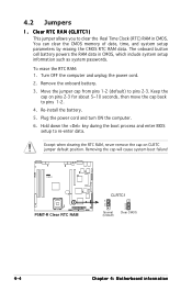
...) to re-enter data. The onboard button cell battery powers the RAM data in CMOS. Hold down the key during the boot process and enter BIOS setup to pins 2-3. Removing the cap will cause system boot failure! ® P5MT-R P5MT-R Clear RTC RAM CLRTC1 1 2 Normal (Default) 2 3 Clear CMOS 4-4 Chapter 4: Motherboard information Remove the...
...) to re-enter data. The onboard button cell battery powers the RAM data in CMOS. Hold down the key during the boot process and enter BIOS setup to pins 2-3. Removing the cap will cause system boot failure! ® P5MT-R P5MT-R Clear RTC RAM CLRTC1 1 2 Normal (Default) 2 3 Clear CMOS 4-4 Chapter 4: Motherboard information Remove the...
User Guide
Page 53
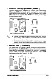
...-up from S1 sleep mode (CPU stopped, DRAM refreshed, system running in the BIOS. ® P5MT-R KBPWR1 1 2 +5V (Default) 2 3 +5VSB P5MT-R Keyboard power setting ASUS RS120-E3/PA4 4-5 Keyboard power (3-pin KBPWR1) This jumper allows you press a key on the +5VSB lead, and a corresponding setting in low power mode) using the connected USB devices. 2.
...-up from S1 sleep mode (CPU stopped, DRAM refreshed, system running in the BIOS. ® P5MT-R KBPWR1 1 2 +5V (Default) 2 3 +5VSB P5MT-R Keyboard power setting ASUS RS120-E3/PA4 4-5 Keyboard power (3-pin KBPWR1) This jumper allows you press a key on the +5VSB lead, and a corresponding setting in low power mode) using the connected USB devices. 2.
User Guide
Page 77
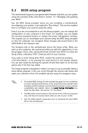
... utility described in section "5.1 Managing and updating your BIOS." Being a menu-driven program, it as easy to enter the Setup utility; ASUS RS120-E3/PA4 5-11 When you start up the computer, the system provides you with its test routines. The Setup program is designed to make...conditions to ensure optimum performance. For example, you can recognize these changes and record them in the CMOS RAM of your selections from the available options using the navigation keys. • The default BIOS settings for this motherboard. The firmware hub on . otherwise, POST continues with...
... utility described in section "5.1 Managing and updating your BIOS." Being a menu-driven program, it as easy to enter the Setup utility; ASUS RS120-E3/PA4 5-11 When you start up the computer, the system provides you with its test routines. The Setup program is designed to make...conditions to ensure optimum performance. For example, you can recognize these changes and record them in the CMOS RAM of your selections from the available options using the navigation keys. • The default BIOS settings for this motherboard. The firmware hub on . otherwise, POST continues with...
User Guide
Page 78
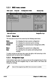
...ESC Exit v02.57 (C)Copyright 1985-2004, American Megatrends, Inc. Some of a menu screen are the navigation keys for that particular menu. Select Screen Select Item +- Use the navigation keys to another. 5-12 Chapter 5: BIOS setup 5.2.1 BIOS menu screen Menu items Menu bar Configuration fields Main ...General help Use [ENTER]. [TAB], or [SHIFT-TAB] to configure system time. Use [+] or [-] to select a field. Sub-menu items Navigation keys 5.2.2 Menu bar The menu bar on top of the screen has the following main items: Main Advanced Power Boot Exit For changing the basic system...
...ESC Exit v02.57 (C)Copyright 1985-2004, American Megatrends, Inc. Some of a menu screen are the navigation keys for that particular menu. Select Screen Select Item +- Use the navigation keys to another. 5-12 Chapter 5: BIOS setup 5.2.1 BIOS menu screen Menu items Menu bar Configuration fields Main ...General help Use [ENTER]. [TAB], or [SHIFT-TAB] to configure system time. Use [+] or [-] to select a field. Sub-menu items Navigation keys 5.2.2 Menu bar The menu bar on top of the screen has the following main items: Main Advanced Power Boot Exit For changing the basic system...
User Guide
Page 79
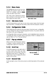
... there are items that do not fit on the screen. To change the value of the selected item. Press the Up/Down arrow keys or / keys to display a pop-up window with the configuration options for that item. 5.2.8 Scroll bar A scroll bar appears on the right side... a field. For example, selecting M a i n shows the Main menu items. The other items on the screen. Use [+] or [-] to select a field. ASUS RS120-E3/PA4 5-13 A configurable field is enclosed in brackets, and is not user-configurable. You cannot select an item that menu. Select Screen Select Item +- Select...
... there are items that do not fit on the screen. To change the value of the selected item. Press the Up/Down arrow keys or / keys to display a pop-up window with the configuration options for that item. 5.2.8 Scroll bar A scroll bar appears on the right side... a field. For example, selecting M a i n shows the Main menu items. The other items on the screen. Use [+] or [-] to select a field. ASUS RS120-E3/PA4 5-13 A configurable field is enclosed in brackets, and is not user-configurable. You cannot select an item that menu. Select Screen Select Item +- Select...
User Guide
Page 86
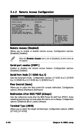
... and parameters Remote Access [Disabled] Serial port number Base Address, IRQ Serial Port Mode Flow Control Redirection After BIOS POST Terminal Type VT-UTFB Combo Key Support Sredir Memory Display Delay [COM1] [3F8h, 4] [115200 8,n,1] [None] [Always] [ANSI] [Enabled] [No Delay] Select Remote Access type. Some operating systems may not work when...
... and parameters Remote Access [Disabled] Serial port number Base Address, IRQ Serial Port Mode Flow Control Redirection After BIOS POST Terminal Type VT-UTFB Combo Key Support Sredir Memory Display Delay [COM1] [3F8h, 4] [115200 8,n,1] [None] [Always] [ANSI] [Enabled] [No Delay] Select Remote Access type. Some operating systems may not work when...
User Guide
Page 87
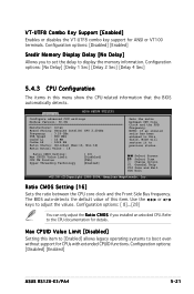
... [Enabled] Enables or disables the VT-UTF8 combo key support for details. Configuration options: [Disabled] [Enabled] Sredir Memory Display Delay [No Delay] Allows you installed an unlocked CPU. Configuration options: [No Delay] [Delay 1 .... Ratio CMOS Setting [16] Sets the ratio between CPU Core Clock and the FSB Frequency. Use the < + > or < - > keys to display the memory information. Configuration options: [Disabled] [Enabled] ASUS RS120-E3/PA4 5-21 Select Screen Select Item +- Refer to boot even without support for CPUs with extended CPUID functions. Max CPUID Value...
... [Enabled] Enables or disables the VT-UTF8 combo key support for details. Configuration options: [Disabled] [Enabled] Sredir Memory Display Delay [No Delay] Allows you installed an unlocked CPU. Configuration options: [No Delay] [Delay 1 .... Ratio CMOS Setting [16] Sets the ratio between CPU Core Clock and the FSB Frequency. Use the < + > or < - > keys to display the memory information. Configuration options: [Disabled] [Enabled] ASUS RS120-E3/PA4 5-21 Select Screen Select Item +- Refer to boot even without support for CPUs with extended CPUID functions. Max CPUID Value...
User Guide
Page 98
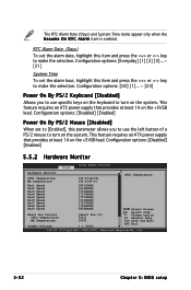
... the system. Fan1 Speed Fan2 Speed Fan3 Speed Fan4 Speed Fan5 Speed Fan6 Speed Fan7 Speed Fan8 Speed Fan9 Speed Smart Fan Control CPU1 Temperature MB Temperature VCORE1 Voltage [8411RPM] [8169RPM] [7594RPM] [7133RPM] [7573RPM] [7336RPM] [7317RPM] [7520RPM] [8598RPM] [Smart Fan II] [061]...2004, American Megatrends, Inc. 5-32 Chapter 5: BIOS setup Configuration options: [00] [1]... ~ [23] Power On By PS/2 Keyboard [Disabled] Allows you to use specific keys on the keyboard to make the selection. The RTC Alarm Date (Days) and System Time items appear only when the R e s u m e O n R T ...
... the system. Fan1 Speed Fan2 Speed Fan3 Speed Fan4 Speed Fan5 Speed Fan6 Speed Fan7 Speed Fan8 Speed Fan9 Speed Smart Fan Control CPU1 Temperature MB Temperature VCORE1 Voltage [8411RPM] [8169RPM] [7594RPM] [7133RPM] [7573RPM] [7336RPM] [7317RPM] [7520RPM] [8598RPM] [Smart Fan II] [061]...2004, American Megatrends, Inc. 5-32 Chapter 5: BIOS setup Configuration options: [00] [1]... ~ [23] Power On By PS/2 Keyboard [Disabled] Allows you to use specific keys on the keyboard to make the selection. The RTC Alarm Date (Days) and System Time items appear only when the R e s u m e O n R T ...
User Guide
Page 99
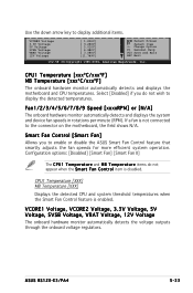
...and device fan speeds in rotations per minute (RPM). CPU1 Temperature [XXX] MB Temperature [XXX] Displays the detected CPU and system threshold temperatures when the Smart...e and M B T e m p e r a t u r e items do not wish to the connector on the motherboard, the field shows N/A. ASUS RS120-E3/PA4 5-33 VCORE1 Voltage, VCORE2 Voltage, 3.3V Voltage, 5V Voltage, 5VSB Voltage, VBAT Voltage, 12V Voltage The onboard hardware monitor automatically detects the voltage outputs... the down arrow key to enable or disable the ASUS Smart Fan Control feature that smartly adjusts the fan speeds...
...and device fan speeds in rotations per minute (RPM). CPU1 Temperature [XXX] MB Temperature [XXX] Displays the detected CPU and system threshold temperatures when the Smart...e and M B T e m p e r a t u r e items do not wish to the connector on the motherboard, the field shows N/A. ASUS RS120-E3/PA4 5-33 VCORE1 Voltage, VCORE2 Voltage, 3.3V Voltage, 5V Voltage, 5VSB Voltage, VBAT Voltage, 12V Voltage The onboard hardware monitor automatically detects the voltage outputs... the down arrow key to enable or disable the ASUS Smart Fan Control feature that smartly adjusts the fan speeds...
User Guide
Page 101
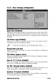
...-2004, American Megatrends, Inc. This will decrease the time needed to enable or disable support for the F1 key to enable or disable the full screen logo display feature. Configuration options: [Disabled] [Enabled] ASUS RS120-E3/PA4 5-35 Configuration options: [Disabled] [Enabled] Set this item allows the BIOS to skip some power on state...
...-2004, American Megatrends, Inc. This will decrease the time needed to enable or disable support for the F1 key to enable or disable the full screen logo display feature. Configuration options: [Disabled] [Enabled] ASUS RS120-E3/PA4 5-35 Configuration options: [Disabled] [Enabled] Set this item allows the BIOS to skip some power on state...
User Guide
Page 105
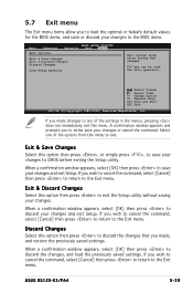
... Megatrends, Inc. If you wish to cancel the command, select [Cancel] then press to return to CMOS before exiting the Setup utility. F10 key can be used for the BIOS items, and save your changes to the Exit menu. Exit & Save Changes Select this option then press , or... you wish to cancel the command, select [Cancel] then press to return to exit the Setup utility without saving your changes and exit Setup. ASUS RS120-E3/PA4 5-39 Discard Changes Select this option then press to discard the changes, and load the previously saved settings. When a confirmation window appears, ...
... Megatrends, Inc. If you wish to cancel the command, select [Cancel] then press to return to CMOS before exiting the Setup utility. F10 key can be used for the BIOS items, and save your changes to the Exit menu. Exit & Save Changes Select this option then press , or... you wish to cancel the command, select [Cancel] then press to return to exit the Setup utility without saving your changes and exit Setup. ASUS RS120-E3/PA4 5-39 Discard Changes Select this option then press to discard the changes, and load the previously saved settings. When a confirmation window appears, ...
User Guide
Page 110
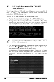
The keys on the legend box vary according to the menu level. 6-4 Chapter 6: RAID configuration During POST, the LSI Logic Embedded SATA RAID Setup Utility automatically detects ... Setup Utility allows you to navigate through the setup menu options or execute commands. To enter the LSI Logic Embedded SATA RAID Setup Utility: 1. The keys on the legend box allow you to create RAID 0, RAID 1, or RAID 10 set (s). Use the arrow...
The keys on the legend box vary according to the menu level. 6-4 Chapter 6: RAID configuration During POST, the LSI Logic Embedded SATA RAID Setup Utility automatically detects ... Setup Utility allows you to navigate through the setup menu options or execute commands. To enter the LSI Logic Embedded SATA RAID Setup Utility: 1. The keys on the legend box allow you to create RAID 0, RAID 1, or RAID 10 set (s). Use the arrow...
User Guide
Page 111
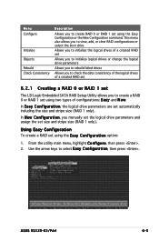
... the New Configuration command. Use the arrow keys to create RAID 0 or RAID 1 set using two types of a created RAID set 6.2.1 Creating a RAID 0 or RAID 1 set The LSI Logic Embedded SATA RAID Setup Utility allows you to create a RAID 0 or RAID 1 set using the E a s y C o n f i g u r a t i o n option: 1. ASUS RS120-E3/PA4 6-5 Menu Configure Initialize Objects Rebuild...
... the New Configuration command. Use the arrow keys to create RAID 0 or RAID 1 set using two types of a created RAID set 6.2.1 Creating a RAID 0 or RAID 1 set The LSI Logic Embedded SATA RAID Setup Utility allows you to create a RAID 0 or RAID 1 set using the E a s y C o n f i g u r a t i o n option: 1. ASUS RS120-E3/PA4 6-5 Menu Configure Initialize Objects Rebuild...
User Guide
Page 114
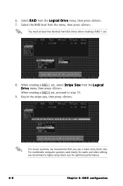
Key-in the stripe size, then press . When creating a RAID 0 set . 8. You need at least two identical hard disk drives when creating a RAID 1 set , proceed to ...
Key-in the stripe size, then press . When creating a RAID 0 set . 8. You need at least two identical hard disk drives when creating a RAID 1 set , proceed to ...
User Guide
Page 116
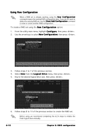
...RAID set using the N e w C o n f i g u r a t i o n option: 1. Use the arrow keys to view or create another RAID configuration. To create a RAID set is already existing, using , we recommend completing the 6.2.4 steps to ...the L o g i c a l D r i v e menu, then press . 5. If you do not want to 13 of the previous section. 4. From the utility main menu, highlight C o n f i g u r e, then press . 2. Key-in the desired logical drive size, then press . 6. Follow steps 3 to 7 of the previous section to create the RAID set , use the V i e w / A d d C o n f i g u r a t i o n command to...
...RAID set using the N e w C o n f i g u r a t i o n option: 1. Use the arrow keys to view or create another RAID configuration. To create a RAID set is already existing, using , we recommend completing the 6.2.4 steps to ...the L o g i c a l D r i v e menu, then press . 5. If you do not want to 13 of the previous section. 4. From the utility main menu, highlight C o n f i g u r e, then press . 2. Key-in the desired logical drive size, then press . 6. Follow steps 3 to 7 of the previous section to create the RAID set , use the V i e w / A d d C o n f i g u r a t i o n command to...
User Guide
Page 117
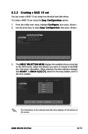
... number, and Y is the drive number. When selected, the drive indicator changes from R E A D Y to the SATA ports. ASUS RS120-E3/PA4 6-11 Select the drive(s) you want to select Easy Configuration, then press . 3. The information of the selected hard disk drive displays... at the bottom of the screen. From the utility main menu, highlight C o n f i g u r e, then press . 2. Use the arrow keys to include in the RAID set using four identical hard disk drives. 6.2.2 Creating a RAID 10 set You can create a RAID 10 set using the E a s y C o n ...
... number, and Y is the drive number. When selected, the drive indicator changes from R E A D Y to the SATA ports. ASUS RS120-E3/PA4 6-11 Select the drive(s) you want to select Easy Configuration, then press . 3. The information of the selected hard disk drive displays... at the bottom of the screen. From the utility main menu, highlight C o n f i g u r e, then press . 2. Use the arrow keys to include in the RAID set using four identical hard disk drives. 6.2.2 Creating a RAID 10 set You can create a RAID 10 set using the E a s y C o n ...
