User Guide
Page 4
... fan with dummy case 2-20 Device fan 2-21 Power supply module 2-22 Optical drive 2-23 Motherboard 2-26 Chapter 3: Installation options 3.1 Rackmount rail kit items 3-2 3.2 Rack rails assembly 3-2 3.3 Attaching the rails to the rack 3-3 3.4 Rackmounting the server 3-4 Chapter 4: Motherboard information 4.1 Motherboard layout 4-2 4.2 Jumpers 4-4 4.3 Connectors 4-9 Chapter 5: BIOS setup 5.1 Managing and updating your BIOS 5-2 5.1.1 Creating a bootable floppy disk 5-2 5.1.2 AFUDOS utility 5-3 5.1.3 ASUS CrashFree BIOS 2 utility 5-6 5.1.4 ASUS Update utility 5-8 5.2 BIOS setup...
... fan with dummy case 2-20 Device fan 2-21 Power supply module 2-22 Optical drive 2-23 Motherboard 2-26 Chapter 3: Installation options 3.1 Rackmount rail kit items 3-2 3.2 Rack rails assembly 3-2 3.3 Attaching the rails to the rack 3-3 3.4 Rackmounting the server 3-4 Chapter 4: Motherboard information 4.1 Motherboard layout 4-2 4.2 Jumpers 4-4 4.3 Connectors 4-9 Chapter 5: BIOS setup 5.1 Managing and updating your BIOS 5-2 5.1.1 Creating a bootable floppy disk 5-2 5.1.2 AFUDOS utility 5-3 5.1.3 ASUS CrashFree BIOS 2 utility 5-6 5.1.4 ASUS Update utility 5-8 5.2 BIOS setup...

User Guide
Page 9
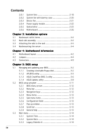
... BIOS Setup menus. Chapter 1: Product Introduction This chapter describes the general features of configuring a server. Chapter 3: Installation options This chapter describes how to when configuring the motherboard. Chapter 6: RAID configuration This chapter tells how to perform when installing or removing system components. 3. Chapter 2: Hardware setup This chapter lists the hardware setup procedures that comes with at least basic knowledge of the server, including sections on front panel and rear panel specifications. 2. Chapter 4: Motherboard...
... BIOS Setup menus. Chapter 1: Product Introduction This chapter describes the general features of configuring a server. Chapter 3: Installation options This chapter describes how to when configuring the motherboard. Chapter 6: RAID configuration This chapter tells how to perform when installing or removing system components. 3. Chapter 2: Hardware setup This chapter lists the hardware setup procedures that comes with at least basic knowledge of the server, including sections on front panel and rear panel specifications. 2. Chapter 4: Motherboard...
User Guide
Page 10
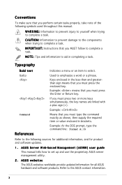
... Command References Indicates a menu or an item to aid in brackets. ASUS Server Web-based Management (ASWM) user guide This manual tells how to the ASUS contact information. W A R N I O N : Information to prevent damage to the components when trying to complete a task. I M P O R T A N T : Instructions that you must press the Enter or Return key. ASUS websites The ASUS websites worldwide provide updated information for product and software updates. 1. If you...
... Command References Indicates a menu or an item to aid in brackets. ASUS Server Web-based Management (ASWM) user guide This manual tells how to the ASUS contact information. W A R N I O N : Information to prevent damage to the components when trying to complete a task. I M P O R T A N T : Instructions that you must press the Enter or Return key. ASUS websites The ASUS websites worldwide provide updated information for product and software updates. 1. If you...

User Guide
Page 13
...debug card. RAID 0, RAID 1, RAID 10, or software RAID 5 configuration using the LSI Logic Embedded SATA RAID controller Management ASUS Server Web-based Management (ASWM) Monitoring Voltage, temperature, and fan speed monitoring Automatic System Restart (ASR) feature P o w e r r e q u i r e m e n t 400 W power supply, 100V~240V, 50Hz~60Hz Dimensions 600 mm (l) x 445 mm (w) x 43.6 mm (h) *The PCI 33/32 bit slot only use for ASUS® Server Management Board Storage 1 x Ultra ATA 100/66/33 device (slim type optical drive) 4 x SATAII-300 hard disk drive with - The server supports the...
...debug card. RAID 0, RAID 1, RAID 10, or software RAID 5 configuration using the LSI Logic Embedded SATA RAID controller Management ASUS Server Web-based Management (ASWM) Monitoring Voltage, temperature, and fan speed monitoring Automatic System Restart (ASR) feature P o w e r r e q u i r e m e n t 400 W power supply, 100V~240V, 50Hz~60Hz Dimensions 600 mm (l) x 445 mm (w) x 43.6 mm (h) *The PCI 33/32 bit slot only use for ASUS® Server Management Board Storage 1 x Ultra ATA 100/66/33 device (slim type optical drive) 4 x SATAII-300 hard disk drive with - The server supports the...
User Guide
Page 15
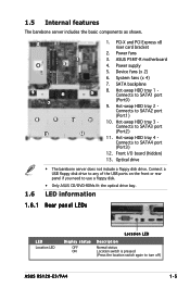
... 8. Hot-swap HDD tray 2 Connects to SATA4 port (Port3) 12. Front I/O board (hidden) 13. Optical drive 1.6 • The barebone server does not include a floppy disk drive. Power supply 5. Hot-swap HDD tray 4 Connects to SATA2 port (Port1) 10. LED information 1.6.1 Rear panel LEDs LED Location LED Display status OFF ON Location LED Description Normal status Location switch is pressed (Press the location switch again to SATA1 port (Port0) 9. Hot-swap HDD tray 1 Connects to turn off) ASUS RS120-E3/PA4 1-5 Device fans (x 2) 6. 1.5 Internal features The barebone...
... 8. Hot-swap HDD tray 2 Connects to SATA4 port (Port3) 12. Front I/O board (hidden) 13. Optical drive 1.6 • The barebone server does not include a floppy disk drive. Power supply 5. Hot-swap HDD tray 4 Connects to SATA2 port (Port1) 10. LED information 1.6.1 Rear panel LEDs LED Location LED Display status OFF ON Location LED Description Normal status Location switch is pressed (Press the location switch again to SATA1 port (Port0) 9. Hot-swap HDD tray 1 Connects to turn off) ASUS RS120-E3/PA4 1-5 Device fans (x 2) 6. 1.5 Internal features The barebone...
User Guide
Page 27
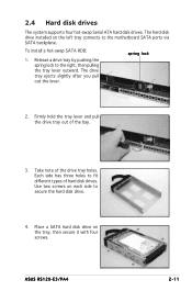
... of hard disk drives. Place a SATA hard disk drive on each side to fit different types of the drive tray holes. 2.4 Hard disk drives The system supports four hot-swap Serial ATA hard disk drives. ASUS RS120-E3/PA4 2-11 Release a drive tray by pushing the spring lock to the motherboard SATA ports via SATA backplane. Firmly hold the tray lever and pull the drive tray out of the bay. 3. The hard disk drive installed on the left tray connects to...
... of hard disk drives. Place a SATA hard disk drive on each side to fit different types of the drive tray holes. 2.4 Hard disk drives The system supports four hot-swap Serial ATA hard disk drives. ASUS RS120-E3/PA4 2-11 Release a drive tray by pushing the spring lock to the motherboard SATA ports via SATA backplane. Firmly hold the tray lever and pull the drive tray out of the bay. 3. The hard disk drive installed on the left tray connects to...
User Guide
Page 29
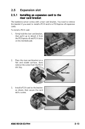
... the card with a riser card bracket. PCI-X slot ASUS RS120-E3/PA4 2-13 Firmly hold the riser card bracket, then pull it from the PCI Express x8 and PCI-X slots on a flat and stable surface, then remove the screw from the PCI-X slot bay. 3. You need to remove the bracket if you want to the riser card bracket The barebone server comes with a screw. 2.5 Expansion slot 2.5.1 Installing an expansion card to install a PCI...
... the card with a riser card bracket. PCI-X slot ASUS RS120-E3/PA4 2-13 Firmly hold the riser card bracket, then pull it from the PCI Express x8 and PCI-X slots on a flat and stable surface, then remove the screw from the PCI-X slot bay. 3. You need to remove the bracket if you want to the riser card bracket The barebone server comes with a screw. 2.5 Expansion slot 2.5.1 Installing an expansion card to install a PCI...
User Guide
Page 31
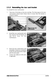
ASUS RS120-E3/PA4 2-15 Install the riser card bracket with the rear panel. 4. Take note of the holes on the motherboard. 3. The three pegs on the riser card bracket 2. Connect the cable(s) to ensure that the bracket is properly in place. 2.5.2 Reinstalling the riser card bracket To reinstall the riser card bracket: 1. Pegs on the riser card bracket should match these holes to the...
ASUS RS120-E3/PA4 2-15 Install the riser card bracket with the rear panel. 4. Take note of the holes on the motherboard. 3. The three pegs on the riser card bracket 2. Connect the cable(s) to ensure that the bracket is properly in place. 2.5.2 Reinstalling the riser card bracket To reinstall the riser card bracket: 1. Pegs on the riser card bracket should match these holes to the...
User Guide
Page 32
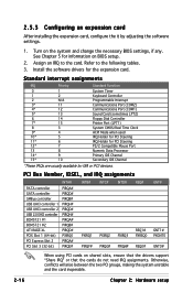
... PCI Steering PS/2 Compatible Mouse Port Numeric Data Processor Primary IDE Channel Secondary IDE Channel *These IRQs are usually available for information on BIOS setup. 2. Otherwise, conflicts will arise between the two PCI groups, making the system unstable and the card inoperable. 2-16 Chapter 2: Hardware setup Install the software drivers for the expansion card. PCI Bus Number, IDSEL, and IRQ assignments INTA# PATA controller SATA controller SMBus controller USB UHCI controller 1 USB UHCI controller 2 USB 2.0 EHCI controller...
... PCI Steering PS/2 Compatible Mouse Port Numeric Data Processor Primary IDE Channel Secondary IDE Channel *These IRQs are usually available for information on BIOS setup. 2. Otherwise, conflicts will arise between the two PCI groups, making the system unstable and the card inoperable. 2-16 Chapter 2: Hardware setup Install the software drivers for the expansion card. PCI Bus Number, IDSEL, and IRQ assignments INTA# PATA controller SATA controller SMBus controller USB UHCI controller 1 USB UHCI controller 2 USB 2.0 EHCI controller...
User Guide
Page 51
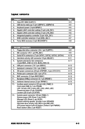
Layout contents Jumpers 1. Force BIOS recovery (3-pin RECOVERY1) Page 4-4 4-5 4-5 4-6 4-6 4-7 4-7 4-8 Internal connectors 1. Printer port connector (26-1 pin LPT1) 10. System panel connector (20-pin PANEL1) System power LED (Green 3-pin PLED) Message LED (Brown 2-pin MLED) System warning speaker (Orange 4-pin SPEAKER) Hard disk drive activity LED (Red 2-pin HDD LED) ATX power button/soft-off button (Yellow 2-pin PWRSW) Reset button (Blue 2-pin RESET) Page 4-9 4-9 4-10 4-11 4-11 4-12 4-12 4-13 4-14 4-14 4-15 4-15 4-16 4-17 ASUS RS120-E3/PA4 4-3 Keyboard power (3-pin KBPWR1) 4....
Layout contents Jumpers 1. Force BIOS recovery (3-pin RECOVERY1) Page 4-4 4-5 4-5 4-6 4-6 4-7 4-7 4-8 Internal connectors 1. Printer port connector (26-1 pin LPT1) 10. System panel connector (20-pin PANEL1) System power LED (Green 3-pin PLED) Message LED (Brown 2-pin MLED) System warning speaker (Orange 4-pin SPEAKER) Hard disk drive activity LED (Red 2-pin HDD LED) ATX power button/soft-off button (Yellow 2-pin PWRSW) Reset button (Blue 2-pin RESET) Page 4-9 4-9 4-10 4-11 4-11 4-12 4-12 4-13 4-14 4-14 4-15 4-15 4-16 4-17 ASUS RS120-E3/PA4 4-3 Keyboard power (3-pin KBPWR1) 4....
User Guide
Page 55
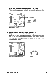
... jumper caps over pins 1-2 if you enable or disable the onboard graphics controller. ® P5MT-R VGA_EN1 12 23 Enable (Default) Disable P5MT-R VGA setting 7. 6. Integrated graphics controller (3-pin VGA_EN1) This jumper allows you want to use the Intel® Matrix Storage Manager utility. ® P5MT-R P5MT-R RAID select jumper RAID_SEL1 1 2 LSI RAID ROM (Default) 2 3 INTEL RAID ROM ASUS RS120-E3/PA4 4-7 RAID controller selection (3-pin RAID_SEL1) This jumper allows you to select the RAID configuration utility to use the LSI Logic Embedded SATA RAID Utility (default...
... jumper caps over pins 1-2 if you enable or disable the onboard graphics controller. ® P5MT-R VGA_EN1 12 23 Enable (Default) Disable P5MT-R VGA setting 7. 6. Integrated graphics controller (3-pin VGA_EN1) This jumper allows you want to use the Intel® Matrix Storage Manager utility. ® P5MT-R P5MT-R RAID select jumper RAID_SEL1 1 2 LSI RAID ROM (Default) 2 3 INTEL RAID ROM ASUS RS120-E3/PA4 4-7 RAID controller selection (3-pin RAID_SEL1) This jumper allows you to select the RAID configuration utility to use the LSI Logic Embedded SATA RAID Utility (default...

User Guide
Page 74
...5.1.4 ASUS Update utility The ASUS Update is a utility that comes with the motherboard package. Installing ASUS Update To install ASUS Update: 1. The D r i v e r s menu appears. 2. The ASUS Update utility is available in the support CD that allows you to your system. This utility is copied to manage, save, and update the motherboard BIOS in the optical drive. Place the support CD in Windows® environment. The ASUS Update utility allows you update the BIOS using this utility. 5-8 Chapter 5: BIOS setup ASUS Update requires an Internet connection either through a network or...
...5.1.4 ASUS Update utility The ASUS Update is a utility that comes with the motherboard package. Installing ASUS Update To install ASUS Update: 1. The D r i v e r s menu appears. 2. The ASUS Update utility is available in the support CD that allows you to your system. This utility is copied to manage, save, and update the motherboard BIOS in the optical drive. Place the support CD in Windows® environment. The ASUS Update utility allows you update the BIOS using this utility. 5-8 Chapter 5: BIOS setup ASUS Update requires an Internet connection either through a network or...
User Guide
Page 77
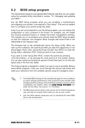
... from the available options using the provided utility described in section "5.1 Managing and updating your system using the BIOS Setup program so that you can change the power management settings. This section explains how to configure your BIOS." ASUS RS120-E3/PA4 5-11 5.2 BIOS setup program This motherboard supports a programmable firmware chip that the computer can recognize these changes and record them in the CMOS RAM of your system, or prompted to "Run Setup". Even if you...
... from the available options using the provided utility described in section "5.1 Managing and updating your system using the BIOS Setup program so that you can change the power management settings. This section explains how to configure your BIOS." ASUS RS120-E3/PA4 5-11 5.2 BIOS setup program This motherboard supports a programmable firmware chip that the computer can recognize these changes and record them in the CMOS RAM of your system, or prompted to "Run Setup". Even if you...
User Guide
Page 83
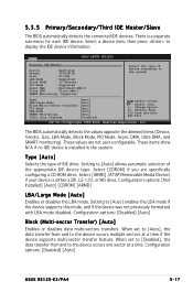
... the appropriate IDE device type. Setting to the device occurs one sector at a time if the device supports multi-sector transfer feature. Configuration options: [Disabled] [Auto] ASUS RS120-E3/PA4 5-17 Configuration options: [Not Installed] [Auto] [CDROM] [ARMD] LBA/Large Mode [Auto] Enables or disables the LBA mode. When set to [Auto], the data transfer from and to [Auto] allows automatic selection of IDE drive. These values are specifically configuring a CD-ROM drive. Configuration options: [Disabled] [Auto] Block...
... the appropriate IDE device type. Setting to the device occurs one sector at a time if the device supports multi-sector transfer feature. Configuration options: [Disabled] [Auto] ASUS RS120-E3/PA4 5-17 Configuration options: [Not Installed] [Auto] [CDROM] [ARMD] LBA/Large Mode [Auto] Enables or disables the LBA mode. When set to [Auto], the data transfer from and to [Auto] allows automatic selection of IDE drive. These values are specifically configuring a CD-ROM drive. Configuration options: [Disabled] [Auto] Block...
User Guide
Page 91
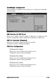
... Port 0 PCI Express Port 4 PCI Express Port 5 [Auto] [Auto] [Auto] To select number of UHCI USB Ports(USB 1.1) to enable a specific number of USB ports, or disable the USB function. USB Function [4 USB Ports] Allows you to be enabled. Configuration options: [Auto] [Disabled] PCI Express Port 5 [Auto] Allows you to enable or disable the USB 2.0 controller. Select Screen Select Item +- Configuration options: [Disabled] [2 USB Ports] [4 USB Ports] USB 2.0 Controller [Disabled] Allows you to set or disable the PCI Express Port 5. Configuration options: [Auto] [Disabled] ASUS RS120-E3...
... Port 0 PCI Express Port 4 PCI Express Port 5 [Auto] [Auto] [Auto] To select number of UHCI USB Ports(USB 1.1) to enable a specific number of USB ports, or disable the USB function. USB Function [4 USB Ports] Allows you to be enabled. Configuration options: [Auto] [Disabled] PCI Express Port 5 [Auto] Allows you to enable or disable the USB 2.0 controller. Select Screen Select Item +- Configuration options: [Disabled] [2 USB Ports] [4 USB Ports] USB 2.0 Controller [Disabled] Allows you to set or disable the PCI Express Port 5. Configuration options: [Auto] [Disabled] ASUS RS120-E3...
User Guide
Page 102
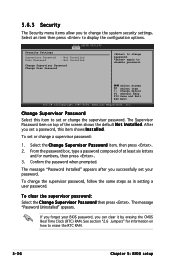
... press to disable password. again to display the configuration options. After you can clear it by erasing the CMOS Real Time Clock (RTC) RAM. The Supervisor Password item on how to change a supervisor password: 1. Confirm the password when prompted. If you forget your password. Security Settings BIOS SETUP UTILITY Boot Supervisor Password : Not Installed User Password : Not Installed Change Supervisor Password Change User Password to erase the RTC RAM. 5-36 Chapter 5: BIOS setup To set your BIOS password, you set a password, this item to set or change the...
... press to disable password. again to display the configuration options. After you can clear it by erasing the CMOS Real Time Clock (RTC) RAM. The Supervisor Password item on how to change a supervisor password: 1. Confirm the password when prompted. If you forget your password. Security Settings BIOS SETUP UTILITY Boot Supervisor Password : Not Installed User Password : Not Installed Change Supervisor Password Change User Password to erase the RTC RAM. 5-36 Chapter 5: BIOS setup To set your BIOS password, you set a password, this item to set or change the...
User Guide
Page 103
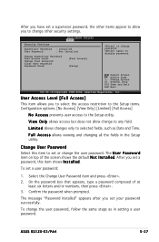
... change to the Setup utility. ASUS RS120-E3/PA4 5-37 After you have set a user password: 1. The U s e r P a s s w o r d item on top of at least six letters and/or numbers, then press . 3. On the password box that appears, type a password composed of the screen shows the default N o t I n s t a l l e d. again to change the user password. To set a supervisor password, the other security settings. Select Screen Select Item +- The message "Password Installed" appears after you to select the access restriction...
... change to the Setup utility. ASUS RS120-E3/PA4 5-37 After you have set a user password: 1. The U s e r P a s s w o r d item on top of at least six letters and/or numbers, then press . 3. On the password box that appears, type a password composed of the screen shows the default N o t I n s t a l l e d. again to change the user password. To set a supervisor password, the other security settings. Select Screen Select Item +- The message "Password Installed" appears after you to select the access restriction...

User Guide
Page 137
... after installing all Serial ATA hard disk drives. 2. ASUS RS120-E3/PA4 6-31 All Rights Reserved. [ MAIN MENU ] 1. 6.3 Intel® Matrix Storage Manager Option ROM Utility The Intel® Matrix Storage Manager Option ROM utility allows you to display the utility main menu. Intel(R) Matrix Storage Manager Option ROM v5.0.0.1032 ICH7R wRAID5 Copyright(C) 2003-05 Intel Corporation. Reset Disks to create RAID 0, RAID 1, RAID 0+1, and RAID 5 set(s) from Serial ATA hard disk drives. Exit RAID Volumes: None defined. [ DISK/VOLUME INFORMATION ] Physical Disks: Port Drive Model...
... after installing all Serial ATA hard disk drives. 2. ASUS RS120-E3/PA4 6-31 All Rights Reserved. [ MAIN MENU ] 1. 6.3 Intel® Matrix Storage Manager Option ROM Utility The Intel® Matrix Storage Manager Option ROM utility allows you to display the utility main menu. Intel(R) Matrix Storage Manager Option ROM v5.0.0.1032 ICH7R wRAID5 Copyright(C) 2003-05 Intel Corporation. Reset Disks to create RAID 0, RAID 1, RAID 0+1, and RAID 5 set(s) from Serial ATA hard disk drives. Exit RAID Volumes: None defined. [ DISK/VOLUME INFORMATION ] Physical Disks: Port Drive Model...

User Guide
Page 153
... . ASUS RS120-E3/PA4 7-5 Intel Matrix Storage Select Intel(R) 82801GR/GH SATA RAID Controller (Desktop ICH7RDH) for windows, first. Please refer chapter 7.1.1 to continue installation. 7. Then, select the "Intel(R) 82801GR/GH SATA AHCI Controller (Desktop ICH7RDH)" from the list. 6. When prompted, press to create the Inter SATA Driver for Intel Matrix Storage RAID mode from the RAID driver disk. If configure SATA as AHCI Mode in the BIOS setup utility of IDE Configuration, you need to continue. Follow screen instructions...
... . ASUS RS120-E3/PA4 7-5 Intel Matrix Storage Select Intel(R) 82801GR/GH SATA RAID Controller (Desktop ICH7RDH) for windows, first. Please refer chapter 7.1.1 to continue installation. 7. Then, select the "Intel(R) 82801GR/GH SATA AHCI Controller (Desktop ICH7RDH)" from the list. 6. When prompted, press to create the Inter SATA Driver for Intel Matrix Storage RAID mode from the RAID driver disk. If configure SATA as AHCI Mode in the BIOS setup utility of IDE Configuration, you need to continue. Follow screen instructions...

User Guide
Page 165
Visit the ASUS website (www.asus.com) for updates. 7.4.1 Running the support CD Place the support CD to run the CD. 7.4.2 Drivers menu The D r i v e r s menu shows the available device drivers if the system detects installed devices. E X E to the optical drive. Install the necessary drivers to avail all motherboard features. ASUS RS120-E3/PA4 7-17 If A u t o r u n is enabled in your computer. 7.4 Management applications and utilities installation The support CD that came with the motherboard package contains the drivers, management applications, and utilities that...
Visit the ASUS website (www.asus.com) for updates. 7.4.1 Running the support CD Place the support CD to run the CD. 7.4.2 Drivers menu The D r i v e r s menu shows the available device drivers if the system detects installed devices. E X E to the optical drive. Install the necessary drivers to avail all motherboard features. ASUS RS120-E3/PA4 7-17 If A u t o r u n is enabled in your computer. 7.4 Management applications and utilities installation The support CD that came with the motherboard package contains the drivers, management applications, and utilities that...


