User Guide
Page 11
It includes sections on front panel and rear panel specifications. Product introduction Chapter 1 This chapter describes the general features of the chassis kit. ASUS RS120-E3 (PA2) 1-1
It includes sections on front panel and rear panel specifications. Product introduction Chapter 1 This chapter describes the general features of the chassis kit. ASUS RS120-E3 (PA2) 1-1

User Guide
Page 13
... (ASR) feature P o w e r r e q u i r e m e n t 400 W power supply, 100V~240V, 50Hz~60Hz Dimensions 600 mm (l) x 445 mm (w) x 43.6 mm (h) ASUS RS120-E3 (PA2) 1-3 RAID 0, RAID 1, or RAID 10 configuration using the Intel® Matrix Storage Manager - Chassis Rackmount 1U (R10) Motherboard ASUS P5MT-R Chipset North Bridge : Intel® E7230 Memory Controller Hub (MCH) South Bridge : Intel® ICH7R...
... (ASR) feature P o w e r r e q u i r e m e n t 400 W power supply, 100V~240V, 50Hz~60Hz Dimensions 600 mm (l) x 445 mm (w) x 43.6 mm (h) ASUS RS120-E3 (PA2) 1-3 RAID 0, RAID 1, or RAID 10 configuration using the Intel® Matrix Storage Manager - Chassis Rackmount 1U (R10) Motherboard ASUS P5MT-R Chipset North Bridge : Intel® E7230 Memory Controller Hub (MCH) South Bridge : Intel® ICH7R...
User Guide
Page 15
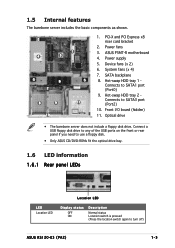
... Connects to SATA3 port (Port2) 10. Front I/O board (hidden) 11. System fans (x 4) 7. PCI-X and PCI Express x8 riser card bracket 2. ASUS P5MT-R motherboard 4. Hot-swap HDD tray 2 Connects to SATA1 port (Port0) 9. Optical drive • The barebone server does not include a floppy disk ...floppy disk. • Only ASUS CD/DVD-ROMs fit the optical drive bay. 1.6 LED information 1.6.1 Rear panel LEDs LED Location LED Location LED Display status OFF ON Description Normal status Location switch is pressed (Press the location switch again to turn off) ASUS RS120-E3 (PA2) 1-5
... Connects to SATA3 port (Port2) 10. Front I/O board (hidden) 11. System fans (x 4) 7. PCI-X and PCI Express x8 riser card bracket 2. ASUS P5MT-R motherboard 4. Hot-swap HDD tray 2 Connects to SATA1 port (Port0) 9. Optical drive • The barebone server does not include a floppy disk ...floppy disk. • Only ASUS CD/DVD-ROMs fit the optical drive bay. 1.6 LED information 1.6.1 Rear panel LEDs LED Location LED Location LED Display status OFF ON Description Normal status Location switch is pressed (Press the location switch again to turn off) ASUS RS120-E3 (PA2) 1-5
User Guide
Page 17
Chapter 2 This chapter lists the hardware setup procedures that you have to perform when installing or removing system components. Hardware setup ASUS RS120-E3 (PA2) 2-1
Chapter 2 This chapter lists the hardware setup procedures that you have to perform when installing or removing system components. Hardware setup ASUS RS120-E3 (PA2) 2-1
User Guide
Page 19
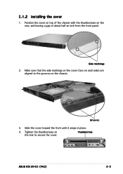
2.1.2 Installing the cover 1. Make sure that the side markings on the cover (two on each side) are aligned to secure the cover. Side markings 2. Slide the cover toward the front until it snaps in place. 4. Position the cover on top of the chassis with the thumbscrews on the chassis. Tighten the thumbscrews on the rear to the grooves on the rear, and leaving a gap of about half an inch from the front panel. Grooves 3. Thumbscrews ASUS RS120-E3 (PA2) 2-3
2.1.2 Installing the cover 1. Make sure that the side markings on the cover (two on each side) are aligned to secure the cover. Side markings 2. Slide the cover toward the front until it snaps in place. 4. Position the cover on top of the chassis with the thumbscrews on the chassis. Tighten the thumbscrews on the rear to the grooves on the rear, and leaving a gap of about half an inch from the front panel. Grooves 3. Thumbscrews ASUS RS120-E3 (PA2) 2-3
User Guide
Page 21
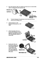
... (A), then move it is on the bottom-left (B) until it to the socket pins, do not remove the PnP cap unless you . Gold triangle mark ASUS RS120-E3 (PA2) A 2-5 The socket alignment A l i g n m e n t k e y key should face you are installing a CPU. 3. Load plate...
... (A), then move it is on the bottom-left (B) until it to the socket pins, do not remove the PnP cap unless you . Gold triangle mark ASUS RS120-E3 (PA2) A 2-5 The socket alignment A l i g n m e n t k e y key should face you are installing a CPU. 3. Load plate...
User Guide
Page 23
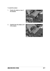
Position the airduct on top of the heatsink. 2. To install the airduct: 1. ASUS RS120-E3 (PA2) 2-7 Carefully lower the airduct until it fits in place.
Position the airduct on top of the heatsink. 2. To install the airduct: 1. ASUS RS120-E3 (PA2) 2-7 Carefully lower the airduct until it fits in place.
User Guide
Page 25
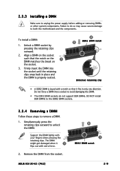
.... 1. Support the DIMM lightly with a notch so that the notch on the 1 DIMM matches the break on the socket. 3. Remove the DIMM from the socket. ASUS RS120-E3 (PA2) 2 1 DDR2 DIMM notch 2-9 The DIMM might get damaged when it fits in place and the DIMM is properly seated. 2 3 DDR2 DIMM notch Unlocked retaining clip...
.... 1. Support the DIMM lightly with a notch so that the notch on the 1 DIMM matches the break on the socket. 3. Remove the DIMM from the socket. ASUS RS120-E3 (PA2) 2 1 DDR2 DIMM notch 2-9 The DIMM might get damaged when it fits in place and the DIMM is properly seated. 2 3 DDR2 DIMM notch Unlocked retaining clip...

User Guide
Page 27
... correctly placed when its front edge aligns with the bay edge. 7. Repeat steps 1 to 6 if you wish to the depth of the tray edge protrudes. ASUS RS120-E3 (PA2) 2-11 Refer to the connectors on the SATA backplane. Connect the bundled SATA cables to section "2.7 SATA backplane cabling" for information on the backplane. 6. SATA...
... correctly placed when its front edge aligns with the bay edge. 7. Repeat steps 1 to 6 if you wish to the depth of the tray edge protrudes. ASUS RS120-E3 (PA2) 2-11 Refer to the connectors on the SATA backplane. Connect the bundled SATA cables to section "2.7 SATA backplane cabling" for information on the backplane. 6. SATA...

User Guide
Page 29
Install a PCI Express x8 card to remove the screw that secures the slot metal cover. 3. Use a Phillips (cross) screwdriver to the bracket as shown, then secure the card with a screw you removed earlier. Remove the slot metal cover, then set it aside. 4. To install a PCI Express x8 card: 1. ASUS RS120-E3 (PA2) 2-13 PCI Express x8 slot 2. Follow steps 1 to 2 of the previous section.
Install a PCI Express x8 card to remove the screw that secures the slot metal cover. 3. Use a Phillips (cross) screwdriver to the bracket as shown, then secure the card with a screw you removed earlier. Remove the slot metal cover, then set it aside. 4. To install a PCI Express x8 card: 1. ASUS RS120-E3 (PA2) 2-13 PCI Express x8 slot 2. Follow steps 1 to 2 of the previous section.
User Guide
Page 31
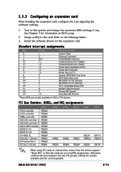
ASUS RS120-E3 (PA2) 2-15 Standard interrupt assignments IRQ Priority 0 1 1 2 2 N/A 3* 11 4* 12 5* 13 6 14 7* 15 8 3 9* 4 10* 5 11* 6 12* 7 13 8 14* 9 15* 10 Standard Function System Timer Keyboard Controller Programmable ...
ASUS RS120-E3 (PA2) 2-15 Standard interrupt assignments IRQ Priority 0 1 1 2 2 N/A 3* 11 4* 12 5* 13 6 14 7* 15 8 3 9* 4 10* 5 11* 6 12* 7 13 8 14* 9 15* 10 Standard Function System Timer Keyboard Controller Programmable ...
User Guide
Page 33
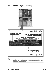
ASUS RS120-E3 (PA2) 2-17 2.7 SATA backplane cabling Connects the device fan cable Connects the SATA cable from SATA1 (Port0) on the MB Connects a 8-pin plug from power supply FAN_IN* connects the fan cable from FRNT_FAN4 on the MB Connect the system fan cables CON1_FAN CON2_FAN CON3_FAN CON4_FAN Connect the SATA HDDs J1: connects the SMBus cable from the MB Connects the SATA cable from SATA3 (Port2) on the MB *The system fans rotate at full speed during power on when the backplane FAN_IN connector cable is not connected to the FRNT_FAN4 connector on the motherboard.
ASUS RS120-E3 (PA2) 2-17 2.7 SATA backplane cabling Connects the device fan cable Connects the SATA cable from SATA1 (Port0) on the MB Connects a 8-pin plug from power supply FAN_IN* connects the fan cable from FRNT_FAN4 on the MB Connect the system fan cables CON1_FAN CON2_FAN CON3_FAN CON4_FAN Connect the SATA HDDs J1: connects the SMBus cable from the MB Connects the SATA cable from SATA3 (Port2) on the MB *The system fans rotate at full speed during power on when the backplane FAN_IN connector cable is not connected to the FRNT_FAN4 connector on the motherboard.
User Guide
Page 35
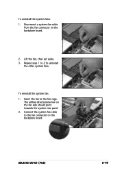
Insert the fan to uninstall the other system fans. Lift the fan, then set aside. 3. The airflow directional arrow on the backplane board. Repeat step 1 to 2 to the fan cage. Connect the system fan cable to the fan connector on the fan side should point towards the system rear panel. 2. Disconnect a system fan cable from the fan connector on the backplane board. 2. ASUS RS120-E3 (PA2) 2-19 To reinstall the system fan: 1. To uninstall the system fans: 1.
Insert the fan to uninstall the other system fans. Lift the fan, then set aside. 3. The airflow directional arrow on the backplane board. Repeat step 1 to 2 to the fan cage. Connect the system fan cable to the fan connector on the fan side should point towards the system rear panel. 2. Disconnect a system fan cable from the fan connector on the backplane board. 2. ASUS RS120-E3 (PA2) 2-19 To reinstall the system fan: 1. To uninstall the system fans: 1.
User Guide
Page 37
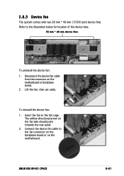
... to the fan cage. 2.8.3 Device fan The system comes with two 28 mm * 40 mm (15500 rpm) device fans. Lift the fan, then set aside. ASUS RS120-E3 (PA2) 2-21 To reinstall the device fan: 1. Insert the fan to the fan connector on the backplane board or on the motherboard. Disconnect the device fan...
... to the fan cage. 2.8.3 Device fan The system comes with two 28 mm * 40 mm (15500 rpm) device fans. Lift the fan, then set aside. ASUS RS120-E3 (PA2) 2-21 To reinstall the device fan: 1. Insert the fan to the fan connector on the backplane board or on the motherboard. Disconnect the device fan...
User Guide
Page 39
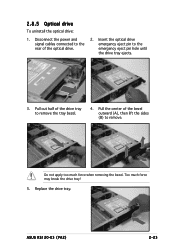
2.8.5 Optical drive To uninstall the optical drive: 1. Pull the center of the optical drive. 2. ASUS RS120-E3 (PA2) 2-23 Disconnect the power and signal cables connected to the rear of the bezel outward (A), then lift the sides (B) to remove. Replace the drive tray. Pull out half of the drive tray to the emergency eject pin hole until the drive tray ejects. 3. Insert the optical drive emergency eject pin to remove the tray bezel. 4. Do not apply too much force may break the drive tray! 5. Too much force when removing the bezel.
2.8.5 Optical drive To uninstall the optical drive: 1. Pull the center of the optical drive. 2. ASUS RS120-E3 (PA2) 2-23 Disconnect the power and signal cables connected to the rear of the bezel outward (A), then lift the sides (B) to remove. Replace the drive tray. Pull out half of the drive tray to the emergency eject pin hole until the drive tray ejects. 3. Insert the optical drive emergency eject pin to remove the tray bezel. 4. Do not apply too much force may break the drive tray! 5. Too much force when removing the bezel.

User Guide
Page 41
... details. 2. Carefully lift the motherboard out of the chassis. Disconnect all the devices from the motherboard. Refer to the base of the chassis as shown. ASUS RS120-E3 (PA2) 2-25 To reinstall the optical drive, follow the instructions in the previous chapter in a reverse order.
... details. 2. Carefully lift the motherboard out of the chassis. Disconnect all the devices from the motherboard. Refer to the base of the chassis as shown. ASUS RS120-E3 (PA2) 2-25 To reinstall the optical drive, follow the instructions in the previous chapter in a reverse order.

User Guide
Page 43
ASUS RS120-E3 (PA2) 2-1 Installation options Chapter 3 This chapter describes how to install the optional components and devices into the barebone server.
ASUS RS120-E3 (PA2) 2-1 Installation options Chapter 3 This chapter describes how to install the optional components and devices into the barebone server.
User Guide
Page 45
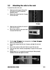
... r e a r 1 U s p a c e that corresponds to the f r o n t 1 U s p a c e where you wish to the rack: 1. Remove the screws from the 1U space on the rack where you attached the rail. 6. ASUS RS120-E3 (PA2) 3-3 Drive in two screws on the outer holes to the 1U space. 4. Select one unit of a rack rail pair to secure the front end. 1U...
... r e a r 1 U s p a c e that corresponds to the f r o n t 1 U s p a c e where you wish to the rack: 1. Remove the screws from the 1U space on the rack where you attached the rail. 6. ASUS RS120-E3 (PA2) 3-3 Drive in two screws on the outer holes to the 1U space. 4. Select one unit of a rack rail pair to secure the front end. 1U...

User Guide
Page 47
ASUS RS120-E3 (PA2) Motherboard info Chapter 4 This chapter includes the motherboard layout, and brief descriptions of the jumpers and internal connectors.
ASUS RS120-E3 (PA2) Motherboard info Chapter 4 This chapter includes the motherboard layout, and brief descriptions of the jumpers and internal connectors.

User Guide
Page 49
... button/soft-off button (Yellow 2-pin PWRSW) Reset button (Blue 2-pin RESET) Page 4-9 4-9 4-10 4-11 4-11 4-12 4-12 4-13 4-14 4-14 4-15 4-15 4-16 4-17 ASUS RS120-E3 (PA2) 4-3
... button/soft-off button (Yellow 2-pin PWRSW) Reset button (Blue 2-pin RESET) Page 4-9 4-9 4-10 4-11 4-11 4-12 4-12 4-13 4-14 4-14 4-15 4-15 4-16 4-17 ASUS RS120-E3 (PA2) 4-3


