User Guide
Page 12
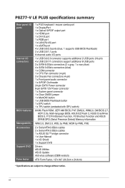
P8Z77-V LE PLUS specifications summary Rear panel I/O ports Internal I/O connectors BIOS features Manageability Accessories Support DVD Form factor 1 x PS/2 keyboard / mouse combo port 1 x DisplayPort 1 x Optical S/PDIF output port 1 x... without notice. button 1 x USB BIOS Flashback button 1 x EPU switch 1 x TPU switch (embeded with GPU switch) 64 Mb Flash ROM, UEFI AMI BIOS, PnP, DMI2.0, WfM2.0, SM BIOS 2.7, ACPI 2.0a, Multi-language BIOS, ASUS EZ Flash 2, ASUS CrashFree BIOS 3, F12 PrintScreen Function, F3 Shortcut Function and ASUS DRAM SPD (Serial Presence Detect) Memory information WfM...
P8Z77-V LE PLUS specifications summary Rear panel I/O ports Internal I/O connectors BIOS features Manageability Accessories Support DVD Form factor 1 x PS/2 keyboard / mouse combo port 1 x DisplayPort 1 x Optical S/PDIF output port 1 x... without notice. button 1 x USB BIOS Flashback button 1 x EPU switch 1 x TPU switch (embeded with GPU switch) 64 Mb Flash ROM, UEFI AMI BIOS, PnP, DMI2.0, WfM2.0, SM BIOS 2.7, ACPI 2.0a, Multi-language BIOS, ASUS EZ Flash 2, ASUS CrashFree BIOS 3, F12 PrintScreen Function, F3 Shortcut Function and ASUS DRAM SPD (Serial Presence Detect) Memory information WfM...
User Guide
Page 16
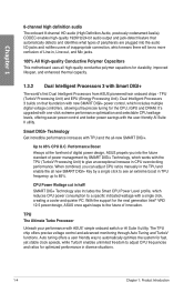
Performance Boost Always at the forefront of digital power design, ASUS propels you can adjust CPU ratios manually in the TPU and enable the all -new SMART DIGI+. TPU (TurboV Processing Unit) and EPU (Energy Processing Unit). Up to the future of innovation. When combined, you into the ... enhanced thermal capacity. 1.3.2 Dual Intelligent Processors 3 with TPU and the all new SMART DIGI+ Key by SMART DIGI+ Technology, which works with ASUS' simple onboard switch or AI Suite II utility. CPU Power Wattage cut in TPU frequency up to give an exceptional increase in CPU overclocking...
Performance Boost Always at the forefront of digital power design, ASUS propels you can adjust CPU ratios manually in the TPU and enable the all -new SMART DIGI+. TPU (TurboV Processing Unit) and EPU (Energy Processing Unit). Up to the future of innovation. When combined, you into the ... enhanced thermal capacity. 1.3.2 Dual Intelligent Processors 3 with TPU and the all new SMART DIGI+ Key by SMART DIGI+ Technology, which works with ASUS' simple onboard switch or AI Suite II utility. CPU Power Wattage cut in TPU frequency up to give an exceptional increase in CPU overclocking...
User Guide
Page 22
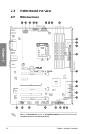
LGA1155 Chapter 2 2.2 Motherboard overview 2.2.1 Motherboard layout KB_USB12 SPDIFO _HDMI _DP 12 3 45 167 24.4cm(9.6in) EATX12V EPU TPU EPU_LED TPU_LED CPU_FAN CHA_FAN2 DIGI+ VRM ASM 1442 DVI_VGA ESATA6G USB3_12 LAN_USB3_E12 8 MemOK! DRAM_LED 1 9 10 2 CHA_FAN3 DDR3 DIMM_A1...module) DDR3 DIMM_B2 (64bit, 240-pin module) EATXPWR 30.5cm(12.0in) AUDIO RTL 8111F CHA_FAN1 PCIEX1_1 Lithium Cell CMOS Power P8Z77-V LE PLUS PCIEX16_1 USB3_34 11 ASM 1042 PCIEX1_2 PCI1 Intel® Z77 Marvell® PCIe SATA 6.0Gb/s controller SATA3G_3 SATA3G_1 SATA6G_1 SATA3G_4 SATA3G_2 ...
LGA1155 Chapter 2 2.2 Motherboard overview 2.2.1 Motherboard layout KB_USB12 SPDIFO _HDMI _DP 12 3 45 167 24.4cm(9.6in) EATX12V EPU TPU EPU_LED TPU_LED CPU_FAN CHA_FAN2 DIGI+ VRM ASM 1442 DVI_VGA ESATA6G USB3_12 LAN_USB3_E12 8 MemOK! DRAM_LED 1 9 10 2 CHA_FAN3 DDR3 DIMM_A1...module) DDR3 DIMM_B2 (64bit, 240-pin module) EATXPWR 30.5cm(12.0in) AUDIO RTL 8111F CHA_FAN1 PCIEX1_1 Lithium Cell CMOS Power P8Z77-V LE PLUS PCIEX16_1 USB3_34 11 ASM 1042 PCIEX1_2 PCI1 Intel® Z77 Marvell® PCIe SATA 6.0Gb/s controller SATA3G_3 SATA3G_1 SATA6G_1 SATA3G_4 SATA3G_2 ...
User Guide
Page 23
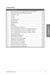
...TPU LED (TPU_LED) 7. MemOK! USB 3.0 connector (20-1 pin USB3_34) 12. Intel® Z77 Serial ATA 3.0 Gb/s connectors (7-pin SATA3G_1~4 [blue]) 15. Digital audio connector (4-1 pin SPDIF_OUT) Page 2-25 2-27 2-21 2-18 2-17 2-21 2-4 2-5 2-20 2-16 2-26 2-27 2-22 2-23 2-20 2-21 2-15 2-28 2-19 2-24 2-26 2-24 2-25 ASUS P8Z77-V LE PLUS... 2-3 Onboard LED (SB_PWR) 16. Clear RTC RAM (3-pin CLRTC) 18. EPU switch 5. BIOS Flashback LED (FLBK_LED) 17. BIOS Flashback button (BIOS_FLBK) 20.
...TPU LED (TPU_LED) 7. MemOK! USB 3.0 connector (20-1 pin USB3_34) 12. Intel® Z77 Serial ATA 3.0 Gb/s connectors (7-pin SATA3G_1~4 [blue]) 15. Digital audio connector (4-1 pin SPDIF_OUT) Page 2-25 2-27 2-21 2-18 2-17 2-21 2-4 2-5 2-20 2-16 2-26 2-27 2-22 2-23 2-20 2-21 2-15 2-28 2-19 2-24 2-26 2-24 2-25 ASUS P8Z77-V LE PLUS... 2-3 Onboard LED (SB_PWR) 16. Clear RTC RAM (3-pin CLRTC) 18. EPU switch 5. BIOS Flashback LED (FLBK_LED) 17. BIOS Flashback button (BIOS_FLBK) 20.
User Guide
Page 38
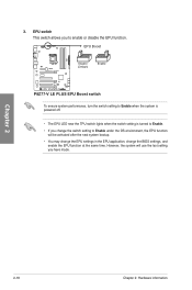
... This switch allows you change the switch setting to enable or disable the EPU function. EPU Boost P8Z77-V LE PLUS P8Z77-V LE PLUS EPU Boost switch To ensure system performance, turn the switch setting to Enable when the system is powered off. • The EPU LED near the TPU switch lights when the switch setting is turned to Enable. • If...
... This switch allows you change the switch setting to enable or disable the EPU function. EPU Boost P8Z77-V LE PLUS P8Z77-V LE PLUS EPU Boost switch To ensure system performance, turn the switch setting to Enable when the system is powered off. • The EPU LED near the TPU switch lights when the switch setting is turned to Enable. • If...
User Guide
Page 41
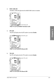
TPU LED The TPU LED lights when the TPU switch is turned to Enable. TPU_LED P8Z77-V LE PLUS P8Z77-V LE PLUS TPU Boost LED ASUS P8Z77-V LE PLUS 2-21 EPU LED The EPU LED lights when the EPU switch is turned to Enable. 3. BIOS_FLBK LED The BIOS_FLBK LED lights when the BIOS-FLBK function is enabled. EPU_LED P8Z77-V LE PLUS P8Z77-V LE PLUS EPU Boost LED 5. Chapter 2 P8Z77-V LE PLUS FLBK_LED P8Z77-V LE PLUS BIOS Flashback LED 4.
TPU LED The TPU LED lights when the TPU switch is turned to Enable. TPU_LED P8Z77-V LE PLUS P8Z77-V LE PLUS TPU Boost LED ASUS P8Z77-V LE PLUS 2-21 EPU LED The EPU LED lights when the EPU switch is turned to Enable. 3. BIOS_FLBK LED The BIOS_FLBK LED lights when the BIOS-FLBK function is enabled. EPU_LED P8Z77-V LE PLUS P8Z77-V LE PLUS EPU Boost LED 5. Chapter 2 P8Z77-V LE PLUS FLBK_LED P8Z77-V LE PLUS BIOS Flashback LED 4.

