User Manual
Page 4
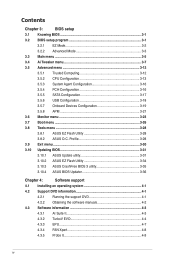
....1 ASUS Update utility 3-31 3.10.2 ASUS EZ Flash Utility 3-34 3.10.3 ASUS CrashFree BIOS 3 utility 3-35 3.10.4 ASUS BIOS Updater 3-36 Chapter 4: Software support 4.1 Installing an operating system 4-1 4.2 Support DVD information 4-1 4.2.1 Running the support DVD 4-1 4.2.2 Obtaining the software manuals 4-2 4.3 Software information 4-3 4.3.1 AI Suite II 4-3 4.3.2 TurboV EVO 4-4 4.3.3 EPU 4-7 4.3.4 FAN Xpert 4-8 4.3.5 Probe II 4-9 iv Contents Chapter 3: BIOS setup 3.1 Knowing BIOS 3-1 3.2 BIOS setup...
....1 ASUS Update utility 3-31 3.10.2 ASUS EZ Flash Utility 3-34 3.10.3 ASUS CrashFree BIOS 3 utility 3-35 3.10.4 ASUS BIOS Updater 3-36 Chapter 4: Software support 4.1 Installing an operating system 4-1 4.2 Support DVD information 4-1 4.2.1 Running the support DVD 4-1 4.2.2 Obtaining the software manuals 4-2 4.3 Software information 4-3 4.3.1 AI Suite II 4-3 4.3.2 TurboV EVO 4-4 4.3.3 EPU 4-7 4.3.4 FAN Xpert 4-8 4.3.5 Probe II 4-9 iv Contents Chapter 3: BIOS setup 3.1 Knowing BIOS 3-1 3.2 BIOS setup...
User Manual
Page 5
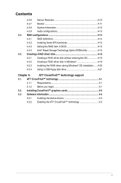
... 4.3.7 Monitor 4-11 4.3.8 System Information 4-12 4.3.9 Audio configurations 4-13 4.4 RAID configurations 4-14 4.4.1 RAID definitions 4-14 4.4.2 Installing Serial ATA hard disks 4-15 4.4.3 Setting the RAID item in BIOS 4-15 4.4.4 Intel® Rapid Storage Technology Option ROM utility 4-15 4.5 Creating a RAID driver disk 4-19 4.5.1 Creating a RAID driver disk without entering the OS 4-19 4.5.2 Creating...
... 4.3.7 Monitor 4-11 4.3.8 System Information 4-12 4.3.9 Audio configurations 4-13 4.4 RAID configurations 4-14 4.4.1 RAID definitions 4-14 4.4.2 Installing Serial ATA hard disks 4-15 4.4.3 Setting the RAID item in BIOS 4-15 4.4.4 Intel® Rapid Storage Technology Option ROM utility 4-15 4.5 Creating a RAID driver disk 4-19 4.5.1 Creating a RAID driver disk without entering the OS 4-19 4.5.2 Creating...

User Manual
Page 8
... by your dealer. Refer to perform when installing system components. Detailed descriptions of the BIOS parameters are not part of the switches, jumpers, and connectors on ASUS hardware and software products. Where to find more information Refer to install and configure multiple... ATI® CrossFireX™ graphics cards. viii ASUS websites The ASUS website provides updated information on the motherboard. • Chapter 3: BIOS setup This chapter tells how to change system settings through the BIOS Setup menus. Optional documentation Your product package may include ...
... by your dealer. Refer to perform when installing system components. Detailed descriptions of the BIOS parameters are not part of the switches, jumpers, and connectors on ASUS hardware and software products. Where to find more information Refer to install and configure multiple... ATI® CrossFireX™ graphics cards. viii ASUS websites The ASUS website provides updated information on the motherboard. • Chapter 3: BIOS setup This chapter tells how to change system settings through the BIOS Setup menus. Optional documentation Your product package may include ...
User Manual
Page 11
... BIOS EZ Mode featuring friendly graphics user interface ASUS Quiet Thermal Solution: - vCore: Adjustable CPU voltage at 100-step - vCCIO: Adjustable I /O ASUS TurboV EVO: - vDRAM Bus: Adjustable Memory voltage at 254-step - TurboV ASUS Power Design: - 8+2 Phase Power Design ASUS EPU: - Anti Surge - BCLK/PEG frequency tuning from 80MHz up to 300MHz at 254-step - ASUS Q-Connector - P8H67-M EVO...
... BIOS EZ Mode featuring friendly graphics user interface ASUS Quiet Thermal Solution: - vCore: Adjustable CPU voltage at 100-step - vCCIO: Adjustable I /O ASUS TurboV EVO: - vDRAM Bus: Adjustable Memory voltage at 254-step - TurboV ASUS Power Design: - 8+2 Phase Power Design ASUS EPU: - Anti Surge - BCLK/PEG frequency tuning from 80MHz up to 300MHz at 254-step - ASUS Q-Connector - P8H67-M EVO...
User Manual
Page 12
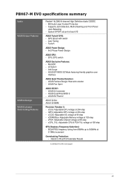
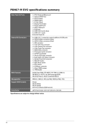
xii P8H67-M EVO specifications summary Back Panel I/O Ports Internal I/O Connectors BIOS Features Manageability Support DVD Contents Form Factor 1 x PS/2 Keyboard/Mouse port 1 x Optical S/PDIF Out 1 x DVI-D Output 1 x HDMI Output 1 x D-Sub Output 1 x Display...CMOS jumper 1 x TPM header 32 Mb Flash ROM, EFI MIOS, PnP, DMI 2.0, WfM 2.0, SM BIOS 2.5, ACPI 2.0a, Multi-language BIOS, ASUS EZ Flash 2, ASUS CrashFree BIOS 3 WfM 2.0, DMI 2.0, WOL by PME, WOR by PME, PXE Drivers ASUS Utilities ASUS Update Anti-virus software (OEM version) uATX Form Factor, 9.6"x 9.6" (24.5cm x 24.5cm) *...
xii P8H67-M EVO specifications summary Back Panel I/O Ports Internal I/O Connectors BIOS Features Manageability Support DVD Contents Form Factor 1 x PS/2 Keyboard/Mouse port 1 x Optical S/PDIF Out 1 x DVI-D Output 1 x HDMI Output 1 x D-Sub Output 1 x Display...CMOS jumper 1 x TPM header 32 Mb Flash ROM, EFI MIOS, PnP, DMI 2.0, WfM 2.0, SM BIOS 2.5, ACPI 2.0a, Multi-language BIOS, ASUS EZ Flash 2, ASUS CrashFree BIOS 3 WfM 2.0, DMI 2.0, WOL by PME, WOR by PME, PXE Drivers ASUS Utilities ASUS Update Anti-virus software (OEM version) uATX Form Factor, 9.6"x 9.6" (24.5cm x 24.5cm) *...
User Manual
Page 16
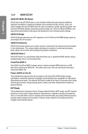
... energy efficiency requirements in line with the same smoothness as their operating system. ASUS Q-Design ASUS Q-Design enhances your DIY experience. ASUS Q-Connector ASUS Q-Connector allows you to update the BIOS without using a bootable floppy disk or an OS-based utility. Power eSATA ...on the Go The motherboard supports hard drives based on external devices. CrashFree BIOS 3 The ASUS CrashFree BIOS 3 allows users to restore corrupted BIOS data from a USB flash disk containing the BIOS file. Easily backup photos, videos and other entertainment contents on the Serial ATA ...
... energy efficiency requirements in line with the same smoothness as their operating system. ASUS Q-Design ASUS Q-Design enhances your DIY experience. ASUS Q-Connector ASUS Q-Connector allows you to update the BIOS without using a bootable floppy disk or an OS-based utility. Power eSATA ...on the Go The motherboard supports hard drives based on external devices. CrashFree BIOS 3 The ASUS CrashFree BIOS 3 allows users to restore corrupted BIOS data from a USB flash disk containing the BIOS file. Easily backup photos, videos and other entertainment contents on the Serial ATA ...
User Manual
Page 29
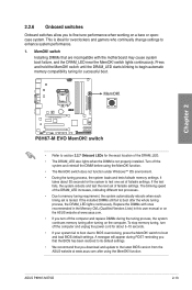
...switch to enhance system performance. 1. function. This is ideal for overclockers and gamers who continually change settings to boot and load BIOS default settings. To stop memory tuning, turn off the system and reinstall the DIMM before using the MemOK! A messgae will... the DRAM_LED lights continuously. MemOK! Chapter 2 • Refer to fine-tune performance when working on the ASUS website at www.asus.com after turning on the computer. ASUS P8H67-M EVO 2-13 2.2.6 Onboard switches Onboard switches allow you to section 2.2.7 Onboard LEDs for the exact location of the...
...switch to enhance system performance. 1. function. This is ideal for overclockers and gamers who continually change settings to boot and load BIOS default settings. To stop memory tuning, turn off the system and reinstall the DIMM before using the MemOK! A messgae will... the DRAM_LED lights continuously. MemOK! Chapter 2 • Refer to fine-tune performance when working on the ASUS website at www.asus.com after turning on the computer. ASUS P8H67-M EVO 2-13 2.2.6 Onboard switches Onboard switches allow you to section 2.2.7 Onboard LEDs for the exact location of the...
User Manual
Page 33
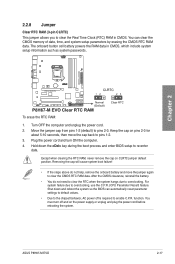
function. ASUS P8H67-M EVO 2-17 Turn OFF the computer and unplug the power cord. 2. Hold down and reboot the system so the BIOS can clear the CMOS memory of date, time, and system setup parameters by erasing the CMOS RTC RAM data. Chapter 2 To erase the RTC RAM: 1. ...; You do not help, remove the onboard battery and move the cap back to enable C.P.R. Shut down the key during the boot process and enter BIOS setup to clear the Real Time Clock (RTC) RAM in CMOS, which include system setup information such as system passwords.
function. ASUS P8H67-M EVO 2-17 Turn OFF the computer and unplug the power cord. 2. Hold down and reboot the system so the BIOS can clear the CMOS memory of date, time, and system setup parameters by erasing the CMOS RTC RAM data. Chapter 2 To erase the RTC RAM: 1. ...; You do not help, remove the onboard battery and move the cap back to enable C.P.R. Shut down the key during the boot process and enter BIOS setup to clear the Real Time Clock (RTC) RAM in CMOS, which include system setup information such as system passwords.
User Manual
Page 34
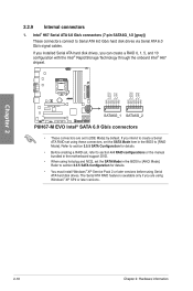
... 6.0 Gb/s connectors (7-pin SATA6G_1/2 [gray]) These connectors connect to section 3.5.5 SATA Configuration for details. • Before creating a RAID set the SATA Mode item in the BIOS to [IDE Mode] by default. Refer to section 3.5.5 SATA Configuration for details. • You must install Windows® XP Service Pack 2 or later versions before... hot-plug and NCQ, set to [AHCI Mode]. The Serial ATA RAID feature is available only if you are set the SATA Mode in the BIOS to [RAID Mode].
... 6.0 Gb/s connectors (7-pin SATA6G_1/2 [gray]) These connectors connect to section 3.5.5 SATA Configuration for details. • Before creating a RAID set the SATA Mode item in the BIOS to [IDE Mode] by default. Refer to section 3.5.5 SATA Configuration for details. • You must install Windows® XP Service Pack 2 or later versions before... hot-plug and NCQ, set to [AHCI Mode]. The Serial ATA RAID feature is available only if you are set the SATA Mode in the BIOS to [RAID Mode].
User Manual
Page 35
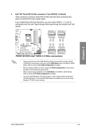
...® H67 chipset. • These connectors are using hot-plug and NCQ, set the SATA Mode item in the BIOS to Serial ATA 3.0 Gb/s hard disk drives and optical disc drives via Serial ATA 3.0 Gb/s signal cables. If ... You must install Windows® XP Service Pack 2 or later versions before using these connectors, set the SATA Mode in the BIOS to [IDE Mode] by default. Intel® H67 Serial ATA 3.0 Gb/s connectors (7-pin SATA3G_3-6 [blue]) These connectors connect...motherboard support DVD. • When using Windows® XP SP2 or later versions. Chapter 2 2. ASUS P8H67-M EVO 2-19
...® H67 chipset. • These connectors are using hot-plug and NCQ, set the SATA Mode item in the BIOS to Serial ATA 3.0 Gb/s hard disk drives and optical disc drives via Serial ATA 3.0 Gb/s signal cables. If ... You must install Windows® XP Service Pack 2 or later versions before using these connectors, set the SATA Mode in the BIOS to [IDE Mode] by default. Intel® H67 Serial ATA 3.0 Gb/s connectors (7-pin SATA3G_3-6 [blue]) These connectors connect...motherboard support DVD. • When using Windows® XP SP2 or later versions. Chapter 2 2. ASUS P8H67-M EVO 2-19
User Manual
Page 39
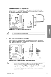
... the BIOS setup to [AC97]. Connect one end of the system chassis. Digital audio connector (4-1 pin SPDIF_OUT) This connector is purchased separately. 8. By default, this connector, then install the module to [HD]. Connect the S/PDIF Out module cable to this connector is for an additional Sony/Philips Digital Interface (S/PDIF) port(s). ASUS P8H67-M EVO...
... the BIOS setup to [AC97]. Connect one end of the system chassis. Digital audio connector (4-1 pin SPDIF_OUT) This connector is purchased separately. 8. By default, this connector, then install the module to [HD]. Connect the S/PDIF Out module cable to this connector is for an additional Sony/Philips Digital Interface (S/PDIF) port(s). ASUS P8H67-M EVO...
User Manual
Page 42
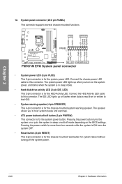
... hear system beeps and warnings. • ATX power button/soft-off the system power. 2-26 Chapter 2: Hardware information The speaker allows you turn on the BIOS settings. The IDE LED lights up when you to this connector. Connect the HDD Activity LED cable to the HDD. • System warning speaker (4-pin...
... hear system beeps and warnings. • ATX power button/soft-off the system power. 2-26 Chapter 2: Hardware information The speaker allows you turn on the BIOS settings. The IDE LED lights up when you to this connector. Connect the HDD Activity LED cable to the HDD. • System warning speaker (4-pin...
User Manual
Page 56
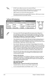
... higher-version DVD player and drivers will black out. Note that DVI-D/HDMI dual output works in OS environment only and that during POST or BIOS setup, only DVI-D output is a configuration example for your USB 3.0 devices. * LAN port LED indications Activity Link LED Status Description OFF No link ORANGE Linked...
... higher-version DVD player and drivers will black out. Note that DVI-D/HDMI dual output works in OS environment only and that during POST or BIOS setup, only DVI-D output is a configuration example for your USB 3.0 devices. * LAN port LED indications Activity Link LED Status Description OFF No link ORANGE Linked...

User Manual
Page 61
...runs the power-on test. After applying power, the system power LED on the chain) c. Refer to the BIOS beep codes table below) or additional messages appear on the BIOS setting. Chapter 2 2.4 Starting up for less than four seconds lets the system enter the soft-off mode ...continuous beep followed by three short beeps One continuous beep followed by four short beeps Description VGA detected Quick boot set to enter the BIOS Setup. ASUS P8H67-M EVO 2-45 Connect the power cord to green after the system LED turns on the devices in Chapter 3. 2.5 Turning off the computer ...
...runs the power-on test. After applying power, the system power LED on the chain) c. Refer to the BIOS beep codes table below) or additional messages appear on the BIOS setting. Chapter 2 2.4 Starting up for less than four seconds lets the system enter the soft-off mode ...continuous beep followed by three short beeps One continuous beep followed by four short beeps Description VGA detected Quick boot set to enter the BIOS Setup. ASUS P8H67-M EVO 2-45 Connect the power cord to green after the system LED turns on the devices in Chapter 3. 2.5 Turning off the computer ...
User Manual
Page 63
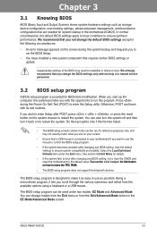
... Advanced Mode. Being a menu-driven program, it as easy to use the mouse to control the BIOS setup program. • If the system becomes unstable after changing any BIOS setting, load the default settings to boot. ASUS P8H67-M EVO 3-1 We recommend that a USB mouse is provided for information on the system chassis to enter the...
... Advanced Mode. Being a menu-driven program, it as easy to use the mouse to control the BIOS setup program. • If the system becomes unstable after changing any BIOS setting, load the default settings to boot. ASUS P8H67-M EVO 3-1 We recommend that a USB mouse is provided for information on the system chassis to enter the...

User Manual
Page 64
...the selected mode on the right hand side Normal mode ASUS Optimal mode Selects the boot device priority • The boot device options vary depending on the devices you to the system. 3-2 Chapter 3: BIOS setup EZ Mode Friday [10/15/2010] P8H67-M EVO BIOS Version : 0243 CPU Type : Genuine Intel(R) CPU ... Boot Menu(F8) Default(F5) Selects the boot device priority Power Saving mode Loads optimized default Displays the system properties of the BIOS setup program Clicks to decide the boot priority. To access the Advanced Mode, click Exit/Advanced Mode, then select Advanced Mode....
...the selected mode on the right hand side Normal mode ASUS Optimal mode Selects the boot device priority • The boot device options vary depending on the devices you to the system. 3-2 Chapter 3: BIOS setup EZ Mode Friday [10/15/2010] P8H67-M EVO BIOS Version : 0243 CPU Type : Genuine Intel(R) CPU ... Boot Menu(F8) Default(F5) Selects the boot device priority Power Saving mode Loads optimized default Displays the system properties of the BIOS setup program Clicks to decide the boot priority. To access the Advanced Mode, click Exit/Advanced Mode, then select Advanced Mode....
User Manual
Page 65
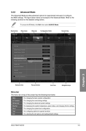
... settings For displaying the system temperature, power status, and changing the fan settings. Back button Menu items Menu bar Configuration fields EFI BIOS Utility - Pop-up window Scroll bar Navigation keys Menu bar The menu bar on top of the Advanced Mode. For changing the .... To access the EZ Mode, click Exit, then select ASUS EZ Mode. The figure below shows an example of the screen has the following sections for special functions For selecting the exit options and loading default settings Chapter 3 ASUS P8H67-M EVO 3-3 F1: General Help F2: Previous Values F5: Optimized ...
... settings For displaying the system temperature, power status, and changing the fan settings. Back button Menu items Menu bar Configuration fields EFI BIOS Utility - Pop-up window Scroll bar Navigation keys Menu bar The menu bar on top of the Advanced Mode. For changing the .... To access the EZ Mode, click Exit, then select ASUS EZ Mode. The figure below shows an example of the screen has the following sections for special functions For selecting the exit options and loading default settings Chapter 3 ASUS P8H67-M EVO 3-3 F1: General Help F2: Previous Values F5: Optimized ...

User Manual
Page 66
...on the right side of a menu screen when there are the navigation keys for that item. Pop-up window with the configuration options for the BIOS setup program. Use the navigation keys to display a pop-up window Select a menu item and press to select items in the menu and ...change the settings. Chapter 3 3-4 Chapter 3: BIOS setup Scroll bar A scroll bar appears on the screen. Press the Up/Down arrow keys or / keys to the previous menu screen. You cannot select...
...on the right side of a menu screen when there are the navigation keys for that item. Pop-up window with the configuration options for the BIOS setup program. Use the navigation keys to display a pop-up window Select a menu item and press to select items in the menu and ...change the settings. Chapter 3 3-4 Chapter 3: BIOS setup Scroll bar A scroll bar appears on the screen. Press the Up/Down arrow keys or / keys to the previous menu screen. You cannot select...

User Manual
Page 67
...to erase the RTC RAM. • The Administrator or User Password items on top of the BIOS Setup program. Advanced Mode Exit Main Ai Tweaker Advanced Monitor BIOS Information BIOS Version Build Date ME Version 0243 x64 10/14/2010 7.0.0.1135 CPU Information Genuine Intel(R) CPU 0... language Security The Security menu items allow you have forgotten your BIOS password, erase the CMOS Real Time Clock (RTC) RAM to set the system date, time, language, and security settings. Chapter 3 ASUS P8H67-M EVO 3-5 See section 2.2.8 Jumper for when entering Setup If ONLY ...
...to erase the RTC RAM. • The Administrator or User Password items on top of the BIOS Setup program. Advanced Mode Exit Main Ai Tweaker Advanced Monitor BIOS Information BIOS Version Build Date ME Version 0243 x64 10/14/2010 7.0.0.1135 CPU Information Genuine Intel(R) CPU 0... language Security The Security menu items allow you have forgotten your BIOS password, erase the CMOS Real Time Clock (RTC) RAM to set the system date, time, language, and security settings. Chapter 3 ASUS P8H67-M EVO 3-5 See section 2.2.8 Jumper for when entering Setup If ONLY ...

User Manual
Page 68
... key in the current password, then press . 3. After you might be able to see or change a user password: 1. Chapter 3 3-6 Chapter 3: BIOS setup The User Password item on top of the screen shows Not Installed. Select the User Password item and press . 2. To set a user password: ...1. Select the Administrator Password item and press . 2. Confirm the password when prompted. To change only selected fields in the BIOS setup program. From the Enter Current Password box, key in a new password, then press . 4. To clear the user password, follow the same ...
... key in the current password, then press . 3. After you might be able to see or change a user password: 1. Chapter 3 3-6 Chapter 3: BIOS setup The User Password item on top of the screen shows Not Installed. Select the User Password item and press . 2. To set a user password: ...1. Select the Administrator Password item and press . 2. Confirm the password when prompted. To change only selected fields in the BIOS setup program. From the Enter Current Password box, key in a new password, then press . 4. To clear the user password, follow the same ...


