User Manual
Page 13
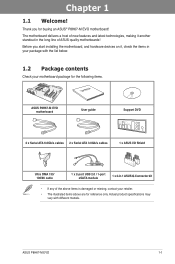
.... • The illustrated items above are for the following items. User Manual ASUS P8H67-M EVO motherboard User guide Support DVD 2 x Serial ATA 6.0Gb/s cables 2 x Serial ATA 3.0Gb/s cables 1 x ASUS I/O Shield Ultra DMA 133/ 100/66 cable 1 x 2-port USB 2.0 / 1-port eSATA module 1 x 2-in-1 ASUS Q-Connector kit • If any of new features and latest technologies, making...
.... • The illustrated items above are for the following items. User Manual ASUS P8H67-M EVO motherboard User guide Support DVD 2 x Serial ATA 6.0Gb/s cables 2 x Serial ATA 3.0Gb/s cables 1 x ASUS I/O Shield Ultra DMA 133/ 100/66 cable 1 x 2-port USB 2.0 / 1-port eSATA module 1 x 2-in-1 ASUS Q-Connector kit • If any of new features and latest technologies, making...
User Manual
Page 15
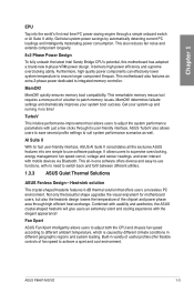
... VRM power design. It delivers high power efficiency and supreme overclocking ability. MemOK! Combined with usability and aesthetics, the ASUS crystal-shaped heatsink will give users an extremely silent and cooling experience with just a few clicks through a simple onboard switch...and cool environment. TurboV This intutive performance-improvement tool allows users to patch memory issues. Get your system boot success. ASUS P8H67-M EVO 1-3 Built-in variety of useful profiles offer flexible controls of fan speed to different ambient temperature, which is caused ...
... VRM power design. It delivers high power efficiency and supreme overclocking ability. MemOK! Combined with usability and aesthetics, the ASUS crystal-shaped heatsink will give users an extremely silent and cooling experience with just a few clicks through a simple onboard switch...and cool environment. TurboV This intutive performance-improvement tool allows users to patch memory issues. Get your system boot success. ASUS P8H67-M EVO 1-3 Built-in variety of useful profiles offer flexible controls of fan speed to different ambient temperature, which is caused ...
User Manual
Page 17
... as the power supply case, to avoid damaging them due to static electricity. • Hold components by the edges to the motherboard, peripherals, or components. ASUS P8H67-M EVO 2-1
... as the power supply case, to avoid damaging them due to static electricity. • Hold components by the edges to the motherboard, peripherals, or components. ASUS P8H67-M EVO 2-1
User Manual
Page 21
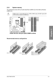
2.2.4 System memory The motherboard comes with four Double Data Rate 3 (DDR3) Dual Inline Memory Modules (DIMM) slots. DO NOT install a DDR or DDR2 memory module to the DDR3 slot. A DDR3 module is notched differently from a DDR or DDR2 module. Recommended memory configurations Chapter 2 ASUS P8H67-M EVO 2-5
2.2.4 System memory The motherboard comes with four Double Data Rate 3 (DDR3) Dual Inline Memory Modules (DIMM) slots. DO NOT install a DDR or DDR2 memory module to the DDR3 slot. A DDR3 module is notched differently from a DDR or DDR2 module. Recommended memory configurations Chapter 2 ASUS P8H67-M EVO 2-5
User Manual
Page 27
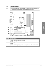
Slot Description 1 PCIe 2.0 x16_1 slot [blue] (at x16 mode) 2 PCIe 2.0 x1_1 slot 3 PCI slot 4 PCIe 2.0 x16_2 slot [black] (at x4 mode, compatible with PCIe x1, x2 and x4 devices) ASUS P8H67-M EVO 2-11 2.2.5 Expansion slots Ensure to do so may cause you physical injury and damage motherboard components. Failure to unplug the power cord before adding or removing expansion cards. Chapter 2 Slot No.
Slot Description 1 PCIe 2.0 x16_1 slot [blue] (at x16 mode) 2 PCIe 2.0 x1_1 slot 3 PCI slot 4 PCIe 2.0 x16_2 slot [black] (at x4 mode, compatible with PCIe x1, x2 and x4 devices) ASUS P8H67-M EVO 2-11 2.2.5 Expansion slots Ensure to do so may cause you physical injury and damage motherboard components. Failure to unplug the power cord before adding or removing expansion cards. Chapter 2 Slot No.
User Manual
Page 29
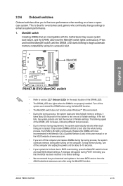
...to fine-tune performance when working on the computer. switch Installing DIMMs that you download and update to the latest BIOS version from the ASUS website at www.asus.com. • If you that the BIOS has been restored to boot and load BIOS default settings. switch until the DRAM_LED starts ...default settings. • We recommend that are incompatible with ones recommended in the Memory QVL (Qualified Vendors Lists) in this user manual or on the ASUS website at www.asus.com after turning on a bare or opencase system. ASUS P8H67-M EVO 2-13 switch lights continuously.
...to fine-tune performance when working on the computer. switch Installing DIMMs that you download and update to the latest BIOS version from the ASUS website at www.asus.com. • If you that the BIOS has been restored to boot and load BIOS default settings. switch until the DRAM_LED starts ...default settings. • We recommend that are incompatible with ones recommended in the Memory QVL (Qualified Vendors Lists) in this user manual or on the ASUS website at www.asus.com after turning on a bare or opencase system. ASUS P8H67-M EVO 2-13 switch lights continuously.
User Manual
Page 31
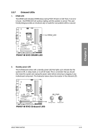
.... If an error is found , the DRAM LED will continue lighting until the problem is ON, in sleep mode, or in any motherboard component. Chapter 2 ASUS P8H67-M EVO 2-15 Standby power LED The motherboard comes with a standby power LED that lights up to locate the root problem within a second. 2. 2.2.7 Onboard LEDs 1. The illustration...
.... If an error is found , the DRAM LED will continue lighting until the problem is ON, in sleep mode, or in any motherboard component. Chapter 2 ASUS P8H67-M EVO 2-15 Standby power LED The motherboard comes with a standby power LED that lights up to locate the root problem within a second. 2. 2.2.7 Onboard LEDs 1. The illustration...
User Manual
Page 33
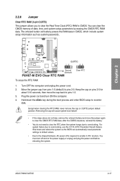
... the power cord before rebooting the system. function. The onboard button cell battery powers the RAM data in CMOS. For system failure due to overclocking. ASUS P8H67-M EVO 2-17 Shut down the key during the boot process and enter BIOS setup to enable C.P.R. Chapter 2 To erase the RTC RAM: 1. 2.2.8 Jumper Clear RTC RAM...
... the power cord before rebooting the system. function. The onboard button cell battery powers the RAM data in CMOS. For system failure due to overclocking. ASUS P8H67-M EVO 2-17 Shut down the key during the boot process and enter BIOS setup to enable C.P.R. Chapter 2 To erase the RTC RAM: 1. 2.2.8 Jumper Clear RTC RAM...
User Manual
Page 35
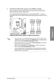
... Serial ATA RAID feature is available only if you intend to create a Serial ATA RAID set using hot-plug and NCQ, set to [AHCI Mode]. ASUS P8H67-M EVO 2-19 If you are set the SATA Mode in the BIOS to Serial ATA 3.0 Gb/s hard disk drives and optical disc drives via Serial ATA...
... Serial ATA RAID feature is available only if you intend to create a Serial ATA RAID set using hot-plug and NCQ, set to [AHCI Mode]. ASUS P8H67-M EVO 2-19 If you are set the SATA Mode in the BIOS to Serial ATA 3.0 Gb/s hard disk drives and optical disc drives via Serial ATA...
User Manual
Page 37
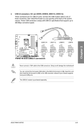
...) to 480 Mbps connection speed. USB 2.0 connectors (10-1 pin USB78, USB910, USB1112, USB1314) These connectors are for USB 2.0 ports. The USB 2.0 module is purchased separately. ASUS P8H67-M EVO 2-21 Chapter 2 Never connect a 1394 cable to a slot opening at the back of the system chassis. 4. Doing so will damage the motherboard! Connect the USB...
...) to 480 Mbps connection speed. USB 2.0 connectors (10-1 pin USB78, USB910, USB1112, USB1314) These connectors are for USB 2.0 ports. The USB 2.0 module is purchased separately. ASUS P8H67-M EVO 2-21 Chapter 2 Never connect a 1394 cable to a slot opening at the back of the system chassis. 4. Doing so will damage the motherboard! Connect the USB...
User Manual
Page 39
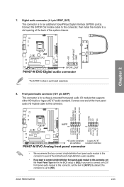
... audio connector (10-1 pin AAFP) This connector is for a chassis-mounted front panel audio I /O module cable to avail of the motherboard's high-definition audio capability. ASUS P8H67-M EVO 2-23 Digital audio connector (4-1 pin SPDIF_OUT) This connector is for an additional Sony/Philips Digital Interface (S/PDIF) port(s). Connect one end of the system chassis...
... audio connector (10-1 pin AAFP) This connector is for a chassis-mounted front panel audio I /O module cable to avail of the motherboard's high-definition audio capability. ASUS P8H67-M EVO 2-23 Digital audio connector (4-1 pin SPDIF_OUT) This connector is for an additional Sony/Philips Digital Interface (S/PDIF) port(s). Connect one end of the system chassis...
User Manual
Page 41
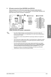
... supply unit (PSU) that you want to use two or more high-end PCI Express x16 cards, use a PSU with more power-consuming devices. ASUS P8H67-M EVO 2-25 otherwise, the system will not boot. • Use of 350 W. • Do not forget to the Recommended Power Supply Wattage Calculator at... http://support.asus. Chapter 2 11. Find the proper orientation and push down firmly until the connectors completely fit. • For a fully configured system, we recommend ...
... supply unit (PSU) that you want to use two or more high-end PCI Express x16 cards, use a PSU with more power-consuming devices. ASUS P8H67-M EVO 2-25 otherwise, the system will not boot. • Use of 350 W. • Do not forget to the Recommended Power Supply Wattage Calculator at... http://support.asus. Chapter 2 11. Find the proper orientation and push down firmly until the connectors completely fit. • For a fully configured system, we recommend ...
User Manual
Page 43
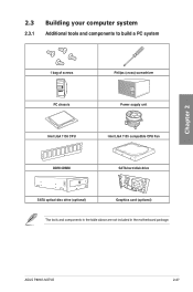
Chapter 2 2.3 Building your computer system 2.3.1 Additional tools and components to build a PC system 1 bag of screws Philips (cross) screwdriver PC chassis Power supply unit Intel LGA 1155 CPU Intel LGA 1155 compatible CPU Fan DDR3 DIMM SATA hard disk drive SATA optical disc drive (optional) Graphics card (optional) The tools and components in the table above are not included in the motherboard package. ASUS P8H67-M EVO 2-27
Chapter 2 2.3 Building your computer system 2.3.1 Additional tools and components to build a PC system 1 bag of screws Philips (cross) screwdriver PC chassis Power supply unit Intel LGA 1155 CPU Intel LGA 1155 compatible CPU Fan DDR3 DIMM SATA hard disk drive SATA optical disc drive (optional) Graphics card (optional) The tools and components in the table above are not included in the motherboard package. ASUS P8H67-M EVO 2-27
User Manual
Page 47
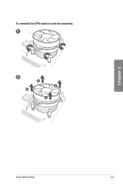
To uninstall the CPU heatsink and fan assembly 1 2 B A B A Chapter 2 ASUS P8H67-M EVO 2-31
To uninstall the CPU heatsink and fan assembly 1 2 B A B A Chapter 2 ASUS P8H67-M EVO 2-31

User Manual
Page 49
The motherboard layout may vary with models, but the installation steps remain the same. 2 Chapter 2 ASUS P8H67-M EVO 2-33 2.3.5 1 Motherboard installation The diagrams in this section are for reference only.
The motherboard layout may vary with models, but the installation steps remain the same. 2 Chapter 2 ASUS P8H67-M EVO 2-33 2.3.5 1 Motherboard installation The diagrams in this section are for reference only.
User Manual
Page 51
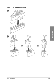
2.3.6 1 ATX Power connection 2 OR OR Chapter 2 ASUS P8H67-M EVO 2-35
2.3.6 1 ATX Power connection 2 OR OR Chapter 2 ASUS P8H67-M EVO 2-35

User Manual
Page 53
Chapter 2 2.3.8 Front I/O Connector To install ASUS Q-Connector 1 2 IDE_LED+ IDE_LED- IDE_LED PWR Ground Reset Ground POWER SW RESET SW To install USB 2.0 Connector To install front panel audio connector USB 2.0 AAFP ASUS P8H67-M EVO 2-37
Chapter 2 2.3.8 Front I/O Connector To install ASUS Q-Connector 1 2 IDE_LED+ IDE_LED- IDE_LED PWR Ground Reset Ground POWER SW RESET SW To install USB 2.0 Connector To install front panel audio connector USB 2.0 AAFP ASUS P8H67-M EVO 2-37
User Manual
Page 55
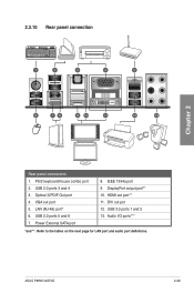
USB 2.0 ports 3 and 4 3. HDMI out port** 11. VGA out port 5. Power External SATA port 8. DVI out pot 12. PS/2 keyboard/mouse combo port 2. USB 2.0 ports 5 and 6 7. DisplayPort output port** 10. USB 3.0 ports 1 and 2 13. LAN (RJ-45) port* 6. IEEE 1394a port 9. Audio I/O ports*** *and **: Refer to the tables on the next page for LAN port and audio port definitions. 2.3.10 Rear panel connection Chapter 2 Rear panel connectors 1. Optical S/PDIF Out port 4. ASUS P8H67-M EVO 2-39
USB 2.0 ports 3 and 4 3. HDMI out port** 11. VGA out port 5. Power External SATA port 8. DVI out pot 12. PS/2 keyboard/mouse combo port 2. USB 2.0 ports 5 and 6 7. DisplayPort output port** 10. USB 3.0 ports 1 and 2 13. LAN (RJ-45) port* 6. IEEE 1394a port 9. Audio I/O ports*** *and **: Refer to the tables on the next page for LAN port and audio port definitions. 2.3.10 Rear panel connection Chapter 2 Rear panel connectors 1. Optical S/PDIF Out port 4. ASUS P8H67-M EVO 2-39
User Manual
Page 57
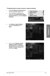
Click Display > General Settings and select a Resolution. ASUS P8H67-M EVO 2-41 Install Intel Graphics Accelerator Driver from the motherboard support DVD. 2. Or you can click Display > General Settings > Scaling > Customize Aspect Ratio. Chapter 2 **Troubleshooting on monitor overscan / underscan problem 1. Click Apply. 4. Move the Horizontal Scaling and Vertical Scaling sliders and then click Apply. From the Windows® notification area, double-click the Intel(R) Graphics Media Accelerator Driver icon and click Graphics Properties. 3.
Click Display > General Settings and select a Resolution. ASUS P8H67-M EVO 2-41 Install Intel Graphics Accelerator Driver from the motherboard support DVD. 2. Or you can click Display > General Settings > Scaling > Customize Aspect Ratio. Chapter 2 **Troubleshooting on monitor overscan / underscan problem 1. Click Apply. 4. Move the Horizontal Scaling and Vertical Scaling sliders and then click Apply. From the Windows® notification area, double-click the Intel(R) Graphics Media Accelerator Driver icon and click Graphics Properties. 3.
User Manual
Page 59
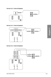
Connect to 2.1 channel Speakers Connect to 4.1 channel Speakers Connect to 5.1 channel Speakers Chapter 2 ASUS P8H67-M EVO 2-43
Connect to 2.1 channel Speakers Connect to 4.1 channel Speakers Connect to 5.1 channel Speakers Chapter 2 ASUS P8H67-M EVO 2-43


