Asus P5GD1 Motherboard - VM
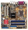
Asus P5GD1 Motherboard
Related Manual Pages


Related Videos

Test Motherboard Asus P5GD1 VM 2
Duration: 2:36
Total Views: 212
Duration: 2:36
Total Views: 212
Test Motherboard Asus P5GD1 VM 1
Duration: 2:36
Total Views: 574
Duration: 2:36
Total Views: 574
Test Motherboard ASUS P5GD1.avi
Duration: 3:22
Total Views: 384
Duration: 3:22
Total Views: 384
Similar Questions

Motherboard Led Blinking
I have a problem with asus motherboard, when i power up i have notice that the Led blink on trhe mo...
I have a problem with asus motherboard, when i power up i have notice that the Led blink on trhe mo...
(Posted by deepsolutions 11 years ago)

Where Is My Model Number On My Motherboard?
Where is my model number on my motherboard?
Where is my model number on my motherboard?
(Posted by johnfiliceiiii 11 years ago)

Where Do I Find A Motherboard Manual?
I need the manual for an Asus M3A78-EMH HDMI Socket AM2+AMD 780G/Hybrid CrossFireX/HDMI/A&V&...
I need the manual for an Asus M3A78-EMH HDMI Socket AM2+AMD 780G/Hybrid CrossFireX/HDMI/A&V&...
(Posted by ke7hhw 12 years ago)
Related Terms
The following terms were also used when searching for Asus P5GD1 Motherboard - VM:- asus motherboard p5gd1-vm
- asus p5gd1
- asus p5gd1 motherboard
- asus p5gd1 pro
- asus p5gd1 vm
- asus p5gd1 vm audio driver
- asus p5gd1 vm audio drivers
- asus p5gd1 vm bios
- asus p5gd1 vm bios update
- asus p5gd1 vm chipset
- asus p5gd1 vm chipset driver
- asus p5gd1 vm driver
- asus p5gd1 vm driver download
- asus p5gd1 vm drivers
- asus p5gd1 vm drivers for windows 7
- asus p5gd1 vm drivers windows 7
- asus p5gd1 vm lan driver
- asus p5gd1 vm lan driver download
- asus p5gd1 vm lga775
- asus p5gd1 vm manual
- asus p5gd1 vm manual download
- asus p5gd1 vm motherboard
- asus p5gd1 vm raid
- asus p5gd1 vm raid driver
- asus p5gd1 vm ram
- asus p5gd1 vm s motherboard
- asus p5gd1 vm specification
- asus p5gd1 vm specs
- asus p5gd1 vm vga driver
- asus p5gd1 vm video driver
- asus p5gd1 vm video driver windows 7
- asus p5gd1 vm win7 drivers
- asus p5gd1 vm windows 7
- asus p5gd1 vm.rom
- asus p5gd1-vm
- asus p5gd1-vm 915g
- asus p5gd1-vm audio drivers
- asus p5gd1-vm bios
- asus p5gd1-vm bios update
- asus p5gd1-vm blank screen
- asus p5gd1-vm cpu support
- asus p5gd1-vm driver
- asus p5gd1-vm driver download
- asus p5gd1-vm drivers
- asus p5gd1-vm drivers download
- asus p5gd1-vm drivers for windows 7
- asus p5gd1-vm drivers windows 7
- asus p5gd1-vm drivers xp
- asus p5gd1-vm dual core cpu
- asus p5gd1-vm help
- asus p5gd1-vm hi definition drivers
- asus p5gd1-vm lan driver
- asus p5gd1-vm lga775
- asus p5gd1-vm manual
- asus p5gd1-vm memory
- asus p5gd1-vm motherboard
- asus p5gd1-vm motherboard driver download
- asus p5gd1-vm motherboard drivers
- asus p5gd1-vm motherboard manual
- asus p5gd1-vm ram
- asus p5gd1-vm rev 1.06
- asus p5gd1-vm sata speed
- asus p5gd1-vm socket 775 motherboard
- asus p5gd1-vm sound drivers
- asus p5gd1-vm specification
- asus p5gd1-vm specifications
- asus p5gd1-vm specs
- asus p5gd1-vm support
- asus p5gd1-vm usb boot
- asus p5gd1-vm vga driver windows 7
- asus p5gd1-vm vga drivers
- asus p5gd1-vm video drivers
- asus p5gd1-vm win7 drivers
- asus p5gd1-vm windows 7
- asus p5gd1-vm windows 7 drivers
- asus p5gd1-vm/s bios
- asus p5gd1-vm/s drivers
- asus p5gd1-vm/s lga 775
- asus p5gd1-vm/s motherboard
- asus p5gd1-vm/s motherboard drivers
- asus p5gd1-vm/s video drivers xp
- asus p5gd1-vmx
- asus p5gd1vm+drivers
- driver asus p5gd1-vm
- driver p5gd1-vm
- p5gd1 asus
- p5gd1 audio driver
- p5gd1 bios
- p5gd1 bios update
- p5gd1 cpu support
- p5gd1 driver
- p5gd1 drivers
- p5gd1 manual
- p5gd1 manual pdf
- p5gd1 memory
- p5gd1 motherboard
- p5gd1 pro asus
- p5gd1 pro bios update
- p5gd1 pro driver
- p5gd1 pro driver windows 7
- p5gd1 pro drivers
- p5gd1 pro manual
- p5gd1 pro specs
- p5gd1 pro windows seven
- p5gd1 specs
- p5gd1 vga drivers
- p5gd1 vga drivers for windows 7
- p5gd1 vm
- p5gd1 vm 1gb memory
- p5gd1 vm asus
- p5gd1 vm audio driver
- p5gd1 vm audio drivers
- p5gd1 vm bios
- p5gd1 vm bios update
- p5gd1 vm chipset
- p5gd1 vm chipset driver
- p5gd1 vm cpu support
- p5gd1 vm driver
- p5gd1 vm driver download
- p5gd1 vm drivers
- p5gd1 vm drivers for win7
- p5gd1 vm drivers for windows 7
- p5gd1 vm drivers windows 7
- p5gd1 vm lan
- p5gd1 vm lan driver
- p5gd1 vm lan driver download
- p5gd1 vm lga775
- p5gd1 vm manual
- p5gd1 vm manual download
- p5gd1 vm memory
- p5gd1 vm motherboard
- p5gd1 vm overclock
- p5gd1 vm raid
- p5gd1 vm raid driver
- p5gd1 vm ram
- p5gd1 vm s drivers
- p5gd1 vm s drivers download
- p5gd1 vm s manual
- p5gd1 vm s motherboard
- p5gd1 vm sata
- p5gd1 vm specification
- p5gd1 vm specs
- p5gd1 vm vga driver
- p5gd1 vm video card
- p5gd1 vm video driver
- p5gd1 vm video driver windows 7
- p5gd1 vm win7 driver
- p5gd1 vm win7 drivers
- p5gd1 vm windows 7
- p5gd1 vm windows 7 drivers
- p5gd1 vm.rom
- p5gd1 windows 7 drivers
- p5gd1- vm se asus
- p5gd1-vm
- p5gd1-vm 915g
- p5gd1-vm asus
- p5gd1-vm asus drivers
- p5gd1-vm asus manual
- p5gd1-vm audio driver
- p5gd1-vm audio driver windows 7
- p5gd1-vm audio drivers
- p5gd1-vm bios
- p5gd1-vm bios flash
- p5gd1-vm bios update
- p5gd1-vm bios update instructions
- p5gd1-vm bios update tool
- p5gd1-vm blank screen
- p5gd1-vm chassis intruded
- p5gd1-vm core 2 duo
- p5gd1-vm cpu
- p5gd1-vm cpu support
- p5gd1-vm ddr memory
- p5gd1-vm download
- p5gd1-vm driver
- p5gd1-vm driver download
- p5gd1-vm drivers
- p5gd1-vm drivers download
- p5gd1-vm drivers for win7
- p5gd1-vm drivers for windows 7
- p5gd1-vm drivers video driver win 8
- p5gd1-vm drivers win7
- p5gd1-vm drivers windows 7
- p5gd1-vm drivers xp
- p5gd1-vm drives for win7
- p5gd1-vm dual core cpu
- p5gd1-vm help
- p5gd1-vm hi definition drivers
- p5gd1-vm lan
- p5gd1-vm lan driver
- p5gd1-vm lga775
- p5gd1-vm manual
- p5gd1-vm manual pdf
- p5gd1-vm memory
- p5gd1-vm memory support
- p5gd1-vm motherboard
- p5gd1-vm motherboard driver download
- p5gd1-vm motherboard drivers
- p5gd1-vm motherboard manual
- p5gd1-vm p4
- p5gd1-vm processor support
- p5gd1-vm raid drivers
- p5gd1-vm ram
- p5gd1-vm rev 1.06
- p5gd1-vm s drivers
- p5gd1-vm s manual
- p5gd1-vm sata speed
- p5gd1-vm secondary ide
- p5gd1-vm socket 775 motherboard
- p5gd1-vm sound driver
- p5gd1-vm sound drivers
- p5gd1-vm specification
- p5gd1-vm specifications
- p5gd1-vm specs
- p5gd1-vm support
- p5gd1-vm usb boot
- p5gd1-vm vga driver
- p5gd1-vm vga driver windows 7
- p5gd1-vm vga drivers
- p5gd1-vm video driver
- p5gd1-vm video drivers
- p5gd1-vm win7
- p5gd1-vm win7 drivers
- p5gd1-vm windows 7
- p5gd1-vm windows 7 driver
- p5gd1-vm windows 7 drivers
- p5gd1-vm windows install problems
- p5gd1-vm/s bios
- p5gd1-vm/s bios update
- p5gd1-vm/s drivers
- p5gd1-vm/s lga 775
- p5gd1-vm/s motherboard
- p5gd1-vm/s motherboard drivers
- p5gd1-vm/s video drivers xp
- p5gd1-vmx
- p5gd1vm audio drivers
- p5gd1vm bios
- p5gd1vm cpu support
- p5gd1vm driver
- p5gd1vm drivers
- p5gd1vm manual
- p5gd1vm motherboard
- p5gd1vm rom
- p5gd1vm specifications
- p5gd1vm windows 7