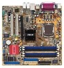
P5GD1-VM User's manual English Edition E1881
Page 12
... it , check the items in the 775-land package. Before you for the following items. Motherboard ASUS P5GD1-VM motherboard Cables 2 x Serial ATA signal cables 1 x Ultra DMA 133/100/66 cable Floppy disk drive cable Accessories I/O shield A p p l i c a t i o n C D s ASUS motherboard support CD D o c u m e n t a t i o n User guide If any of the above items...Intel® Pentium® 4 processor in your package with the list below. 1.2 Package contents Check your motherboard package for buying an ASUS® P5GD1-VM motherboard! See the Appendix for details. 1.1 Welcome!
P5GD1-VM User's manual English Edition E1881
Page 13
... details. PCI Express features point-to 150 MB/s data transfer rate. Serial ATA technology The motherboard supports the Serial ATA technology through the optional ASUS DVI-ADD2 card. ASUS P5GD1-VM 1-3 Enhanced Intel SpeedStep® Technology (EIST) The Enhanced Intel SpeedStep® Technology (EIST) intelligently manages the CPU resources by carrying data in the...
P5GD1-VM User's manual English Edition E1881
Page 15
... • Hold components by the edges to avoid touching the ICs on them. • Whenever you uninstall any motherboard component. P5GD1-VM ® P5GD1-VM Onboard LED SB_PWR1 ON Standby Power OFF Powered Off ASUS P5GD1-VM 1-5 This is a reminder that you install or remove any component, ensure that the ATX power supply is ON, in sleep...
P5GD1-VM User's manual English Edition E1881
Page 17
The edge with external ports goes to the chassis. Doing so can damage the motherboard. Do not overtighten the screws! Place this side towards the rear of the chassis as indicated in the correct orientation. 1.5.2 Placement direction When installing the motherboard, make sure that you place it into the chassis in the image below. 1.5.3 Screw holes Place eight (8) screws into the holes indicated by circles to secure the motherboard to the rear part of the chassis P5GD1-VM ASUS P5GD1-VM 1-7
P5GD1-VM User's manual English Edition E1881
Page 19
Gold triangle mark ASUS P5GD1-VM A 1-9 Retention tab A Load lever PnP cap B This side of the socket box should fit into the CPU notch. Lift the load plate with your thumb ...
P5GD1-VM User's manual English Edition E1881
Page 21
... fan assembly such that the four fasteners match the holes on top of the groove pointing outward. (The photo shows the groove shaded for emphasis.) ASUS P5GD1-VM 1-11
P5GD1-VM User's manual English Edition E1881
Page 23
Pull up two fasteners at a time in a diagonal sequence to disengage the heatsink B and fan assembly from the connector on the motherboard. 2. Rotate each fastener counterclockwise. 3. Disconnect the CPU fan cable from the A motherboard. 1.6.3 Uninstalling the CPU heatsink and fan To uninstall the CPU heatsink and fan: 1. A B A B B A ASUS P5GD1-VM 1-13
P5GD1-VM User's manual English Edition E1881
Page 25
ASUS P5GD1-VM 1-15 1.7 System memory 1.7.1 DIMM sockets location The motherboard comes with the same CAS latency. For optimum compatibility, it is recommended that you installed four 1 GB ... DIMMs into the DIMM sockets using the memory configurations in this section. • For dual-channel configuration, the total size of the sockets: P5GD1-VM DIMM_A1 DIMM_A2 DIMM_B1 DIMM_B2 ® P5GD1-VM 184-Pin DDR DIMM Sockets Channel Channel A Channel B Sockets DIMM_A1 and DIMM_B1 DIMM_A2 and DIMM_B2 Color Blue Black 1.7.2 Memory Configurations You may...
P5GD1-VM User's manual English Edition E1881
Page 27
... only one direction. Failure to do so may cause severe damage to unlock the DIMM. 1 1 DDR DIMM notch Support the DIMM lightly with extra force. 2. ASUS P5GD1-VM 1-17
P5GD1-VM User's manual English Edition E1881
Page 29
IRQ assignments for ISA or PCI devices. shared - - shared shared - shared used - - - - shared - - - - - shared shared - - - shared - - shared - - - ASUS P5GD1-VM 1-19 shared - -- shared - - - used G H - When using PCI cards on shared slots, ensure that the drivers support "Share IRQ" or that the cards do not need ...
P5GD1-VM User's manual English Edition E1881
Page 31
... battery powers the RAM data in CMOS. Turn OFF the computer and unplug the power cord. 2. Reinstall the battery. 5. P5GD1-VM ® P5GD1-VM Clear RTC RAM CLRTC1 12 23 Normal (Default) Clear CMOS ASUS P5GD1-VM 1-21 Keep the cap on CLRTC jumper default position. Removing the cap will cause system boot failure! Remove the onboard...
P5GD1-VM User's manual English Edition E1881
Page 33
... recommend the use of a 4-pin CPU fan. 1.10 Connectors 1.10.1 Rear panel connectors 1 2 34 5 6 7 8 14 13 12 11 10 9 1 . P a r a l l e l p o r t . This port is for a PS/2 mouse. 2 . ASUS P5GD1-VM 1-23 P S / 2 m o u s e p o r t ( g r e e n ) . This 25-pin port connects a parallel printer, a scanner, or other devices. 3 . Fan power (3-pin FANPWR1) Set this jumper to 2-3 if you are using a 4-pin...
P5GD1-VM User's manual English Edition E1881
Page 35
...(40-1 pin PRI_IDE1) This connector is for the jumper settings. • Pin 20 on the IDE connector is removed to PIN 1. ® P5GD1-VM P5GD1-VM IDE connector PIN 1 ASUS P5GD1-VM 1-25 Floppy disk drive connector (34-1 pin FLOPPY1) This connector is for an Ultra DMA 100/66 IDE master device (hard disk drive). FLOPPY1... cable for the primary IDE connector on the floppy ribbon cable to the signal connector at the back of the floppy disk drive. P5GD1-VM 1.10.2 Internal connectors 1 . Insert one end of the cable to this connector, then connect the other end to PIN 1. ® PIN...
P5GD1-VM User's manual English Edition E1881
Page 37
4. GND RSATA_TXP4 RSATA_TXN4 GND RSATA_RXP4 RSATA_RXN4 GND SATA4 GND RSATA_TXP3 RSATA_TXN3 GND RSATA_RXP3 RSATA_RXN3 GND P5GD1-VM GND RSATA_TXP2 RSATA_TXN2 GND RSATA_RXP2 RSATA_RXN2 GND SATA3 ® SATA2 P5GD1-VM SATA connectors SATA1 GND RSATA_TXP1 RSATA_TXN1 GND RSATA_RXP1 RSATA_RXN1 GND Important notes on Serial ATA • You must install Windows® 2000 Service Pack 4 or ... SATA1 or SATA2 connector. Serial ATA Master/Slave connectors Connector Color Setting SATA1, SATA2 SATA3, SATA4 Red Black Master Slave Use Boot Disk Data Disk ASUS P5GD1-VM 1-27
P5GD1-VM User's manual English Edition E1881
Page 39
6 . ASUS P5GD1-VM 1-29 Doing so will damage the motherboard! P5GD1-VM USB+5V USB_P8USB_P8+ GND NC USB+5V USB_P6USB_P6+ GND NC ® USB56 1 P5GD1-VM USB 2.0 connectors USB78 1 USB+5V USB_P7USB_P7+ GND USB+5V USB_P5USB_P5+ GND Never connect a 1394 cable to a slot opening at the back of the system chassis. ...
P5GD1-VM User's manual English Edition E1881
Page 41
... CD1) This connector is for the 4-pin audio cable that connects to use the high-definition audio features of the optical drive. ASUS P5GD1-VM 1-31 Front panel audio connector (10-1 pin AAFP1) This connector is for a chassis-mounted front panel audio I/O module that you... AC'97-compliant pin definition pin definition GND PRESENCE# SENSE1_RETUR SENSE2_RETUR AGND NC NC NC P5GD1-VM MIC2 MICPWR Line out_R NC Line out_L PORT1 L PORT1 R PORT2 R SENSE_SEND PORT2 L AAFP1 ® P5GD1-VM Analog front panel connector We recommend that supports either HD Audio or legacy AC'97 audio...
P5GD1-VM User's manual English Edition E1881
Page 43
... to a slot opening at the back of the system chassis. P5GD1-VM +5V SPDIFOUT GND ® SPDIF_OUT1 P5GD1-VM Digital audio connector 13 Power LED Lead (3-1 pin PLED1) This 3-1 pin connector is for the system power LED. P5GD1-VM PLED+ NC PLED- ® P5GD1-VM PLED setting PLED1 1 ASUS P5GD1-VM 1-33 The S/PDIF module is in sleep mode. Connect the...
P5GD1-VM User's manual English Edition E1881
Page 45
Detailed descriptions of the BIOS parameters are also provided. 2 BIOS setup ASUS P5GD1-VM 2-1 This chapter tells how to change the system settings through the BIOS Setup menus.
P5GD1-VM User's manual English Edition E1881
Page 47
... filename not more than eight alphanumeric characters for the main filename and three alphanumeric characters for reference only. e. A:\>afudos /oOLDBIOS1.ROM Main filename Extension name ASUS P5GD1-VM 2-3 From the Open field, type D:\bootdisk\makeboot a: assuming that you created earlier. 2. This utility also allows you to copy the current BIOS file that D: is...
P5GD1-VM User's manual English Edition E1881
Page 49
...utility. Floppy found , EZ Flash performs the BIOS update process and automatically reboots the system when done. ASUS P5GD1-VM 2-5 The utility returns to the floppy disk drive. A:\>afudos /iP5GD1-VM.ROM AMI Firmware Update Utility - Version 1.10 Copyright (C) 2002 American Megatrends, Inc. done Writing flash...contains the BIOS file to the DOS prompt after the BIOS update process is found ! R O M. 2. Reading file "P5GD1-VM.ROM". Visit the ASUS website (www.asus.com) to download the latest BIOS file for the motherboard and rename the same to go through the long process of ...