User Manual
Page 3
... Memory configurations 1-4 1.5 Expansion slots 1-8 1.5.1 Installing an expansion card 1-8 1.5.2 Configuring an expansion card 1-8 1.5.3 PCI slot 1-8 1.5.4 PCI Express x1 slots 1-8 1.5.5 PCI Express x16 slot 1-8 1.6 Jumpers 1-9 1.7 Connectors 1-10 1.7.1 Rear panel connectors 1-10 1.7.2 Internal connectors 1-12 1.8 Software support 1-16 1.8.1 Installing an operating system 1-16 1.8.2 Support DVD information 1-16 Chapter 2: BIOS information 2.1 Managing and updating your BIOS 2-1 2.1.1 ASUS Update utility 2-1 2.1.2 ASUS EZ Flash 2 2-2 2.1.3 ASUS CrashFree BIOS 2-3 2.2 BIOS setup...
... Memory configurations 1-4 1.5 Expansion slots 1-8 1.5.1 Installing an expansion card 1-8 1.5.2 Configuring an expansion card 1-8 1.5.3 PCI slot 1-8 1.5.4 PCI Express x1 slots 1-8 1.5.5 PCI Express x16 slot 1-8 1.6 Jumpers 1-9 1.7 Connectors 1-10 1.7.1 Rear panel connectors 1-10 1.7.2 Internal connectors 1-12 1.8 Software support 1-16 1.8.1 Installing an operating system 1-16 1.8.2 Support DVD information 1-16 Chapter 2: BIOS information 2.1 Managing and updating your BIOS 2-1 2.1.1 ASUS Update utility 2-1 2.1.2 ASUS EZ Flash 2 2-2 2.1.3 ASUS CrashFree BIOS 2-3 2.2 BIOS setup...
User Manual
Page 8
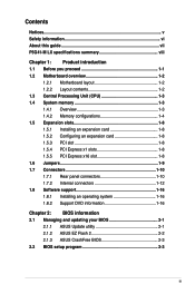
... user manual for Intel® CPU support list. resolution of 3GB system memory if you install a total memory of 4GB capacity or more, Windows® 32-bit operating system may only recognize less than 3GB. We recommend a maximum of 2048 x 1536 @75HZ - P5G41-M LX specifications summary CPU Chipset Front Side Bus Memory Graphics Expansion slots Storage LAN Audio USB ASUS special features LGA775 socket for Intel® Core™2 Quad / Core™2 Extreme / Core™2 Duo / Pentium® Dual-Core...
... user manual for Intel® CPU support list. resolution of 3GB system memory if you install a total memory of 4GB capacity or more, Windows® 32-bit operating system may only recognize less than 3GB. We recommend a maximum of 2048 x 1536 @75HZ - P5G41-M LX specifications summary CPU Chipset Front Side Bus Memory Graphics Expansion slots Storage LAN Audio USB ASUS special features LGA775 socket for Intel® Core™2 Quad / Core™2 Extreme / Core™2 Duo / Pentium® Dual-Core...
User Manual
Page 9
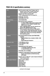
... keyboard port 1 x PS/2 mouse port 1 x COM port 1 x VGA port 1 x LAN (RJ-45) port 4 x USB 2.0/1.1 ports 6-channel audio I/O ports 2 x USB 2.0 connectors supports additional 4 USB 2.0 ports 1 x IDE connector 4 x Serial ATA connectors 1 x High definition front panel audio connector 1 x System panel connector 1 x Internal speaker connector 1 x CPU fan connector 1 x Chassis fan connector 1 x 24-pin EATX power connector 1 x 4-pin ATX 12V power connector 8Mb Flash ROM, AMI BIOS, PnP, DMI 2.0, WfM 2.0, ACPI v2.0a, SM BIOS v2.5 Drivers ASUS PC Probe II ASUS LiveUpdate Utility Anti-virus software (OEM...
... keyboard port 1 x PS/2 mouse port 1 x COM port 1 x VGA port 1 x LAN (RJ-45) port 4 x USB 2.0/1.1 ports 6-channel audio I/O ports 2 x USB 2.0 connectors supports additional 4 USB 2.0 ports 1 x IDE connector 4 x Serial ATA connectors 1 x High definition front panel audio connector 1 x System panel connector 1 x Internal speaker connector 1 x CPU fan connector 1 x Chassis fan connector 1 x 24-pin EATX power connector 1 x 4-pin ATX 12V power connector 8Mb Flash ROM, AMI BIOS, PnP, DMI 2.0, WfM 2.0, ACPI v2.0a, SM BIOS v2.5 Drivers ASUS PC Probe II ASUS LiveUpdate Utility Anti-virus software (OEM...
User Manual
Page 11
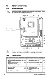
... 1: Product introduction CPU and chassis fan connectors (4-pin CPU_FAN, 3-pin CHA_FAN) 4. DDR2 DIMM slots 7. Speaker connector (4-pin SPEAKER) 1-3 12. Onboard LED (SB_PWR) 1-3 13. System panel connector (10-1 pin F_PANEL) 1-9 14. USB device wake-up (3-pin USBPW1-4, 3-pin USBPW5-8) 5. VGA CPU_FAN USB34 CHA_FAN USBPW1-4 LAN1_USB12 LGA775 Intel® G41 24.4cm(9.6in) EATXPWR AUDIO 2 RTL 8103EL PCIEX16 ICS 9LRS954 7 Super I/O PCIEX1_1 Lithium Cell CMOS Power Intel® 8 ICH7 PCIEX1_2 P5G41-M LX SATA2 SATA4 CLRTC 8Mb 8 BIOS ALC PCI1 SATA1...
... 1: Product introduction CPU and chassis fan connectors (4-pin CPU_FAN, 3-pin CHA_FAN) 4. DDR2 DIMM slots 7. Speaker connector (4-pin SPEAKER) 1-3 12. Onboard LED (SB_PWR) 1-3 13. System panel connector (10-1 pin F_PANEL) 1-9 14. USB device wake-up (3-pin USBPW1-4, 3-pin USBPW5-8) 5. VGA CPU_FAN USB34 CHA_FAN USBPW1-4 LAN1_USB12 LGA775 Intel® G41 24.4cm(9.6in) EATXPWR AUDIO 2 RTL 8103EL PCIEX16 ICS 9LRS954 7 Super I/O PCIEX1_1 Lithium Cell CMOS Power Intel® 8 ICH7 PCIEX1_2 P5G41-M LX SATA2 SATA4 CLRTC 8Mb 8 BIOS ALC PCI1 SATA1...
User Manual
Page 17
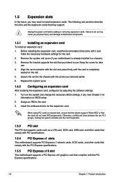
... the card to the chassis with it by adjusting the software settings. 1. Turn on BIOS setup. 2. Install the software drivers for information on the system and change the necessary BIOS settings, if any. When using PCI cards on the slot. 5. Keep the screw for the card. 2. Before installing the expansion card, read the documentation that came with the screw you physical injury and damage motherboard components. 1.5.1 Installing an expansion card To install an expansion card: 1. Failure...
... the card to the chassis with it by adjusting the software settings. 1. Turn on BIOS setup. 2. Install the software drivers for information on the system and change the necessary BIOS settings, if any. When using PCI cards on the slot. 5. Keep the screw for the card. 2. Before installing the expansion card, read the documentation that came with the screw you physical injury and damage motherboard components. 1.5.1 Installing an expansion card To install an expansion card: 1. Failure...
User Manual
Page 19
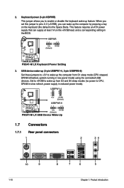
... low power mode) using the connected USB devices. Set to +5VSB to wake up from S3 and S4 sleep modes (no power to wake up (3-pin USBPW1-4, 3-pin USBPW5-8) Set these jumpers to +5V to CPU, DRAM in slow refresh, power supply in the BIOS. This feature requires an ATX power supply that can wake up feature. When you can supply at least 1A on the keyboard (the default is the Space Bar)s. KBPWR 12 23 +5V +5VSB (Default) P5G41-M LX P5G41-M LX Keyboard Power Setting...
... low power mode) using the connected USB devices. Set to +5VSB to wake up from S3 and S4 sleep modes (no power to wake up (3-pin USBPW1-4, 3-pin USBPW5-8) Set these jumpers to +5V to CPU, DRAM in slow refresh, power supply in the BIOS. This feature requires an ATX power supply that can wake up feature. When you can supply at least 1A on the keyboard (the default is the Space Bar)s. KBPWR 12 23 +5V +5VSB (Default) P5G41-M LX P5G41-M LX Keyboard Power Setting...
User Manual
Page 20
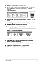
... the LAN port LED indications. Refer to the audio configuration table below for the function of this port becomes Front Speaker Out. 5. Video Graphics Adapter (VGA) port. This port connects the tape, CD, DVD player, or other VGA-compatible devices. 9. These two 4-pin Universal Serial Bus (USB) ports are available for a PS/2 keyboard. Microphone port (pink). This port is for connecting USB 2.0 devices. 8. This port connects a microphone. 1. This port is for a PS/2 mouse. 2. Line Out port (lime). ASUS P5G41-M LX 1-11 This 15-pin port is for a VGA monitor...
... the LAN port LED indications. Refer to the audio configuration table below for the function of this port becomes Front Speaker Out. 5. Video Graphics Adapter (VGA) port. This port connects the tape, CD, DVD player, or other VGA-compatible devices. 9. These two 4-pin Universal Serial Bus (USB) ports are available for a PS/2 keyboard. Microphone port (pink). This port is for connecting USB 2.0 devices. 8. This port connects a microphone. 1. This port is for a PS/2 mouse. 2. Line Out port (lime). ASUS P5G41-M LX 1-11 This 15-pin port is for a VGA monitor...
User Manual
Page 22
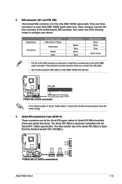
... GND RSATA_TXP2 RSATA_TXN2 GND RSATA_RXP2 RSATA_RXN2 GND P5G41-M LX SATA connectors ASUS P5G41-M LX 1-13 3. Serial ATA connectors (7-pin SATA1-4) These connectors are three connectors on the IDE ribbon cable to PIN 1. Single device Two devices Drive jumper setting Cable-Select or Master Cable-Select Master Slave Mode of the Serial ATA 3Gb/s is for Ultra DMA 100/66 IDE devices. The data transfer rate of device(s) - IDE connector (40-1 pin PRI_IDE) The onboard IDE connector is faster than the standard parallel ATA...
... GND RSATA_TXP2 RSATA_TXN2 GND RSATA_RXP2 RSATA_RXN2 GND P5G41-M LX SATA connectors ASUS P5G41-M LX 1-13 3. Serial ATA connectors (7-pin SATA1-4) These connectors are three connectors on the IDE ribbon cable to PIN 1. Single device Two devices Drive jumper setting Cable-Select or Master Cable-Select Master Slave Mode of the Serial ATA 3Gb/s is for Ultra DMA 100/66 IDE devices. The data transfer rate of device(s) - IDE connector (40-1 pin PRI_IDE) The onboard IDE connector is faster than the standard parallel ATA...
User Manual
Page 25
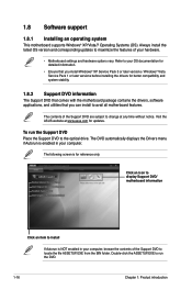
... versions / Windows® Vista Service Pack 1 or later versions before installing the drivers for updates. Click an icon to display Support DVD/ motherboard information Click an item to the optical drive. The following screen is enabled in your hardware. • Motherboard settings and hardware options vary. Always install the latest OS version and corresponding updates to maximize the features of your computer, browse the contents of the Support DVD are subject to change...
... versions / Windows® Vista Service Pack 1 or later versions before installing the drivers for updates. Click an icon to display Support DVD/ motherboard information Click an item to the optical drive. The following screen is enabled in your hardware. • Motherboard settings and hardware options vary. Always install the latest OS version and corresponding updates to maximize the features of your computer, browse the contents of the Support DVD are subject to change...
User Manual
Page 26
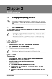
... Internet connection either through a network or an Internet Service Provider (ISP). • This utility is available in the support DVD that you need to restore the BIOS in the future. Copy the original motherboard BIOS using this utility. From the Windows® desktop, click Start > Programs > ASUS > ASUSUpdate > ASUSUpdate to complete the installation. ASUS P5G41-M LX 2-1 Installing ASUS Update To install ASUS Update: 1. Quit all Windows® applications before you to avoid network traffic, or click Auto Select...
... Internet connection either through a network or an Internet Service Provider (ISP). • This utility is available in the support DVD that you need to restore the BIOS in the future. Copy the original motherboard BIOS using this utility. From the Windows® desktop, click Start > Programs > ASUS > ASUSUpdate > ASUSUpdate to complete the installation. ASUS P5G41-M LX 2-1 Installing ASUS Update To install ASUS Update: 1. Quit all Windows® applications before you to avoid network traffic, or click Auto Select...
User Manual
Page 27
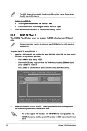
... the updating process. 2.1.2 ASUS EZ Flash 2 The ASUS EZ Flash 2 feature allows you start using an OS‑based utility. Press to switch between drives until the correct BIOS file is found . Updating from a file, then click Next. ASUSTek EZ Flash 2 BIOS ROM Utility V3.36 FLASH TYPE: MXIC 25L8005 Current ROM BOARD: P5G41-M-LX VER: 0307 (H:00 B:01) DATE: 07/21/2009 Update ROM BOARD: Unknown VER: Unknown DATE: Unknown PATH: A:\ A: Note [Enter] Select or Load [Tab] Switch [Up...
... the updating process. 2.1.2 ASUS EZ Flash 2 The ASUS EZ Flash 2 feature allows you start using an OS‑based utility. Press to switch between drives until the correct BIOS file is found . Updating from a file, then click Next. ASUSTek EZ Flash 2 BIOS ROM Utility V3.36 FLASH TYPE: MXIC 25L8005 Current ROM BOARD: P5G41-M-LX VER: 0307 (H:00 B:01) DATE: 07/21/2009 Update ROM BOARD: Unknown VER: Unknown DATE: Unknown PATH: A:\ A: Note [Enter] Select or Load [Tab] Switch [Up...
User Manual
Page 28
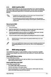
... you to the floppy disk drive, if supported. 3. ASUS P5G41-M LX 2-3 Download the latest BIOS file from the ASUS website at startup: • Press during the updating process. Entering BIOS Setup after POST To enter BIOS Setup after POST: • Press ++ simultaneously. • Press the reset button on the system chassis. • Press the power button to section 2.8 Exit menu for the BIOS file. For motherboards without the floppy connector, prepare a USB flash disk before using this option only if you in the support DVD may not be...
... you to the floppy disk drive, if supported. 3. ASUS P5G41-M LX 2-3 Download the latest BIOS file from the ASUS website at startup: • Press during the updating process. Entering BIOS Setup after POST To enter BIOS Setup after POST: • Press ++ simultaneously. • Press the reset button on the system chassis. • Press the power button to section 2.8 Exit menu for the BIOS file. For motherboards without the floppy connector, prepare a USB flash disk before using this option only if you in the support DVD may not be...
User Manual
Page 29
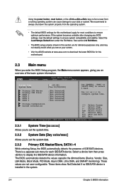
... compatibility and stability. Using the power button, reset button, or the ++ keys to force reset from the operating system. • The default BIOS settings for this motherboard. 2.3 Main menu When you enter the BIOS Setup program, the Main menu screen appears, giving you an overview of IDE/SATA devices. We recommend to always shut down the system properly from a running operating system can cause damage to your screen. • Visit the ASUS website at www.asus...
... compatibility and stability. Using the power button, reset button, or the ++ keys to force reset from the operating system. • The default BIOS settings for this motherboard. 2.3 Main menu When you enter the BIOS Setup program, the Main menu screen appears, giving you an overview of IDE/SATA devices. We recommend to always shut down the system properly from a running operating system can cause damage to your screen. • Visit the ASUS website at www.asus...
User Manual
Page 30
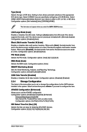
... [20] [25] [30] [35] ASUS P5G41-M LX 2-5 Configuration options: [Not Installed] [Auto] [CDROM] [ARMD] This item does not appear when you are specifically configuring a CD-ROM drive. Setting to [Auto] enables the LBA mode if the device supports this menu allow you to the device occurs multiple sectors at a time. Configuration options: [Disabled] [Auto] PIO Mode [Auto] Selects the PIO mode. Configuration options: [Auto] SMART Monitoring [Auto] Sets the Smart Monitoring, Analysis, and Reporting Technology. Select ARMD (ATAPI Removable Media Device) if your device is either a ZIP, LS-120...
... [20] [25] [30] [35] ASUS P5G41-M LX 2-5 Configuration options: [Not Installed] [Auto] [CDROM] [ARMD] This item does not appear when you are specifically configuring a CD-ROM drive. Setting to [Auto] enables the LBA mode if the device supports this menu allow you to the device occurs multiple sectors at a time. Configuration options: [Disabled] [Auto] PIO Mode [Auto] Selects the PIO mode. Configuration options: [Auto] SMART Monitoring [Auto] Sets the Smart Monitoring, Analysis, and Reporting Technology. Select ARMD (ATAPI Removable Media Device) if your device is either a ZIP, LS-120...

User Manual
Page 31
...Memory Displays the auto-detected system memory. 2.4 Advanced menu The Advanced menu items allow you set overclocking parameters. The value of CPU overclocking options to 800. Overclock Profile - 2.3.5 System Information This menu gives you to adjust the system frequency/voltage. The BIOS automatically detects the items in this menu. Processor Displays the auto-detected CPU specification. Main Advanced Power BIOS SETUP UTILITY Boot Tools Exit JumperFree Configuration CPU Configuration Chipset Onboard Devices Configuration USB Configuration PCIPnP Adjust System frequency...
...Memory Displays the auto-detected system memory. 2.4 Advanced menu The Advanced menu items allow you set overclocking parameters. The value of CPU overclocking options to 800. Overclock Profile - 2.3.5 System Information This menu gives you to adjust the system frequency/voltage. The BIOS automatically detects the items in this menu. Processor Displays the auto-detected CPU specification. Main Advanced Power BIOS SETUP UTILITY Boot Tools Exit JumperFree Configuration CPU Configuration Chipset Onboard Devices Configuration USB Configuration PCIPnP Adjust System frequency...
User Manual
Page 34
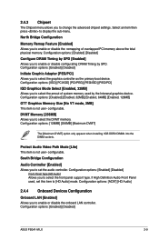
... Panel Type [HD Audio] Allows you to set this item to select the DVMT memory. configurable. Configuration options: [Enabled] [Disabled] ASUS P5G41-M LX 2-9 Configuration options: [Enabled] [Disabled] Configure DRAM Timing by SPD [Enabled] Allows you to select the graphics controller as the primary boot device. configurable. Configuration options: [Disabled] [Enabled, 32MB] [Enabled, 64MB] [Enabled, 128MB] GTT Graphics Memory Size [No VT mode, 2MB] This item is not user- Configuration options: [128MB] [256MB] [Maximum DVMT] The [Maximum DVMT] option only appears when installing...
... Panel Type [HD Audio] Allows you to set this item to select the DVMT memory. configurable. Configuration options: [Enabled] [Disabled] ASUS P5G41-M LX 2-9 Configuration options: [Enabled] [Disabled] Configure DRAM Timing by SPD [Enabled] Allows you to select the graphics controller as the primary boot device. configurable. Configuration options: [Disabled] [Enabled, 32MB] [Enabled, 64MB] [Enabled, 128MB] GTT Graphics Memory Size [No VT mode, 2MB] This item is not user- Configuration options: [128MB] [256MB] [Maximum DVMT] The [Maximum DVMT] option only appears when installing...
User Manual
Page 35
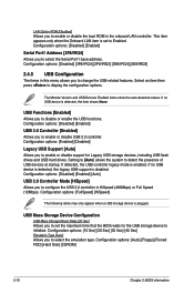
... USB controller legacy mode is set the maximum time that the BIOS waits for Legacy USB storage devices, including USB flash drives and USB hard drives. This item appears only when the Onboard LAN item is enabled. Configuration options: [FullSpeed] [HiSpeed] The following items may only appear when a USB storage device is plugged. LAN Option ROM [Disabled] Allows you to disable or enable the USB functions. USB Functions [Enabled] Allows you to change the USB-related features. Configuration options: [10 Sec] [20 Sec] [30 Sec] [40 Sec] Emulation Type [Auto...
... USB controller legacy mode is set the maximum time that the BIOS waits for Legacy USB storage devices, including USB flash drives and USB hard drives. This item appears only when the Onboard LAN item is enabled. Configuration options: [FullSpeed] [HiSpeed] The following items may only appear when a USB storage device is plugged. LAN Option ROM [Disabled] Allows you to disable or enable the USB functions. USB Functions [Enabled] Allows you to change the USB-related features. Configuration options: [10 Sec] [20 Sec] [30 Sec] [40 Sec] Emulation Type [Auto...
User Manual
Page 36
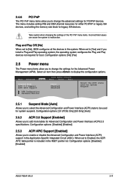
... [Disabled] [Enabled] ASUS P5G41-M LX 2-11 Configuration options: [No] [Yes] 2.5 Power menu The Power menu items allow you to be used for System Suspend. 2.5.1 Suspend Mode [Auto] Allows you to select the Advanced Configuration and Power Interface (ACPI) state to change the settings for the Advanced Power Management (APM). Select an item then press to change the advanced settings for PCI/PnP devices. Main Advanced Power BIOS SETUP UTILITY Boot Tools Exit Suspend Mode [Auto] ACPI 2.0 Support [Enabled] ACPI APIC Support [Enabled] APM Configuration Hardware Monitor...
... [Disabled] [Enabled] ASUS P5G41-M LX 2-11 Configuration options: [No] [Yes] 2.5 Power menu The Power menu items allow you to be used for System Suspend. 2.5.1 Suspend Mode [Auto] Allows you to select the Advanced Configuration and Power Interface (ACPI) state to change the settings for the Advanced Power Management (APM). Select an item then press to change the advanced settings for PCI/PnP devices. Main Advanced Power BIOS SETUP UTILITY Boot Tools Exit Suspend Mode [Auto] ACPI 2.0 Support [Enabled] ACPI APIC Support [Enabled] APM Configuration Hardware Monitor...
User Manual
Page 38
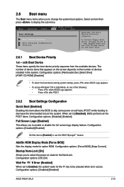
... the display mode for the F1 key to be pressed when error occurs. Main Advanced Power BIOS SETUP UTILITY Boot Tools Exit Boot Settings Boot Device Priority Boot Settings Configuration Security Specifies the Boot Device Priority sequence. Select an item then press to use the ASUS MyLogo2™ feature. Configuration options: [Removable Dev.] [Hard Drive] [ATAPI CD-ROM] [Disabled] • To select the boot device during system startup, press when ASUS Logo appears. • To access Windows® OS in the system. Configuration options: [Disabled] [Enabled] ASUS P5G41-M LX...
... the display mode for the F1 key to be pressed when error occurs. Main Advanced Power BIOS SETUP UTILITY Boot Tools Exit Boot Settings Boot Device Priority Boot Settings Configuration Security Specifies the Boot Device Priority sequence. Select an item then press to use the ASUS MyLogo2™ feature. Configuration options: [Removable Dev.] [Hard Drive] [ATAPI CD-ROM] [Disabled] • To select the boot device during system startup, press when ASUS Logo appears. • To access Windows® OS in the system. Configuration options: [Disabled] [Enabled] ASUS P5G41-M LX...
User Manual
Page 40
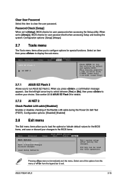
Password Check [Setup] When set to [Setup], BIOS checks for the BIOS items, and save or discard your choice. Main Advanced Power BIOS SETUP UTILITY Boot Tools Exit ASUS EZ Flash 2 AI NET 2 Press ENTER to run ASUS EZ Flash 2. See section 2.1.2 ASUS EZ Flash 2 for special functions. Configuration options: [Disabled] [Enabled] 2.8 Exit menu The Exit menu items allow you to load the optimal or failsafe default values for user password when accessing the Setup utility. F1F010kekyeycacnanbebeusuesded fofrorthtihsisopoepreartaitoino.n. Select+FFEEFFEo-11Sn11Sn0Ct0CeeorSSCGSEf ...
Password Check [Setup] When set to [Setup], BIOS checks for the BIOS items, and save or discard your choice. Main Advanced Power BIOS SETUP UTILITY Boot Tools Exit ASUS EZ Flash 2 AI NET 2 Press ENTER to run ASUS EZ Flash 2. See section 2.1.2 ASUS EZ Flash 2 for special functions. Configuration options: [Disabled] [Enabled] 2.8 Exit menu The Exit menu items allow you to load the optimal or failsafe default values for user password when accessing the Setup utility. F1F010kekyeycacnanbebeusuesded fofrorthtihsisopoepreartaitoino.n. Select+FFEEFFEo-11Sn11Sn0Ct0CeeorSSCGSEf ...


