
User Manual
Page 1
P5G41-M LX Motherboard
P5G41-M LX Motherboard
User Manual
Page 3
Contents Notices...v Safety information vi About this guide vii P5G41-M LX specifications summary viii Chapter 1: Product introduction 1.1 Before you proceed 1-1 1.2 Motherboard overview 1-2 1.2.1 Motherboard layout 1-2 1.2.2 Layout contents 1-2 1.3 Central Processing Unit (CPU 1-3 1.4 System memory 1-3 1.4.1 Overview 1-3 1.4.2 Memory configurations 1-4 1.5 Expansion slots... DVD information 1-16 Chapter 2: BIOS information 2.1 Managing and updating your BIOS 2-1 2.1.1 ASUS Update utility 2-1 2.1.2 ASUS EZ Flash 2 2-2 2.1.3 ASUS CrashFree BIOS 2-3 2.2 BIOS setup program 2-3 iii
Contents Notices...v Safety information vi About this guide vii P5G41-M LX specifications summary viii Chapter 1: Product introduction 1.1 Before you proceed 1-1 1.2 Motherboard overview 1-2 1.2.1 Motherboard layout 1-2 1.2.2 Layout contents 1-2 1.3 Central Processing Unit (CPU 1-3 1.4 System memory 1-3 1.4.1 Overview 1-3 1.4.2 Memory configurations 1-4 1.5 Expansion slots... DVD information 1-16 Chapter 2: BIOS information 2.1 Managing and updating your BIOS 2-1 2.1.1 ASUS Update utility 2-1 2.1.2 ASUS EZ Flash 2 2-2 2.1.3 ASUS CrashFree BIOS 2-3 2.2 BIOS setup program 2-3 iii

User Manual
Page 5
... of Chemicals) regulatory framework, we published the chemical substances in our products at ASUS REACH website at http://green.asus.com/english/REACH.htm. REACH Complying with the REACH (Registration, Evaluation, Authorisation,... and Restriction of the FCC Rules. If this equipment. Operation is connected. • Consult the dealer or an experienced radio/TV technician for a Class B digital device, pursuant to comply with the limits for help. DO NOT throw the motherboard...
... of Chemicals) regulatory framework, we published the chemical substances in our products at ASUS REACH website at http://green.asus.com/english/REACH.htm. REACH Complying with the REACH (Registration, Evaluation, Authorisation,... and Restriction of the FCC Rules. If this equipment. Operation is connected. • Consult the dealer or an experienced radio/TV technician for a Class B digital device, pursuant to comply with the limits for help. DO NOT throw the motherboard...

User Manual
Page 6
...grounding circuit. • Ensure that all power cables are unplugged. • Seek professional assistance before using an adapter or extension cord. This motherboard should only be included in fire. Contact a qualified service technician or your retailer. • The optical S/PDIF is broken, do not... before you detect any area where it may become wet. vi If you are not damaged. Operation safety • Before installing the motherboard and adding devices on a stable surface. • If you are connected. Safety information Electrical safety • To prevent electric shock ...
...grounding circuit. • Ensure that all power cables are unplugged. • Seek professional assistance before using an adapter or extension cord. This motherboard should only be included in fire. Contact a qualified service technician or your retailer. • The optical S/PDIF is broken, do not... before you detect any area where it may become wet. vi If you are not damaged. Operation safety • Before installing the motherboard and adding devices on a stable surface. • If you are connected. Safety information Electrical safety • To prevent electric shock ...
User Manual
Page 7
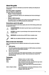
...product package may have been added by your dealer. Example: ++ vii Detailed descriptions of the BIOS parameters are not part of the motherboard and the new technology it supports. • Chapter 2: BIOS information This chapter tells how to the following parts: • Chapter...Indicates a menu or an item to emphasize a word or a phrase. ASUS websites The ASUS website provides updated information on ASUS hardware and software products. If you need when installing and configuring the motherboard. Used to select. About this guide This user guide contains the information you...
...product package may have been added by your dealer. Example: ++ vii Detailed descriptions of the BIOS parameters are not part of the motherboard and the new technology it supports. • Chapter 2: BIOS information This chapter tells how to the following parts: • Chapter...Indicates a menu or an item to emphasize a word or a phrase. ASUS websites The ASUS website provides updated information on ASUS hardware and software products. If you need when installing and configuring the motherboard. Used to select. About this guide This user guide contains the information you...
User Manual
Page 10
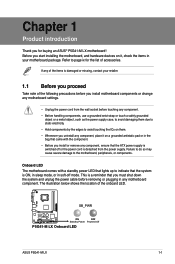
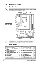
.... • Unplug the power cord from the power supply. Onboard LED The motherboard comes with a standby power LED that lights up to page ix for buying an ASUS® P5G41-M LX motherboard! SB_PWR P5G41-M LX ON OFF Standby Power Powered Off P5G41-M LX Onboard LED ASUS P5G41-M LX 1-1 The illustration below shows the location of the following precautions before you proceed Take...
.... • Unplug the power cord from the power supply. Onboard LED The motherboard comes with a standby power LED that lights up to page ix for buying an ASUS® P5G41-M LX motherboard! SB_PWR P5G41-M LX ON OFF Standby Power Powered Off P5G41-M LX Onboard LED ASUS P5G41-M LX 1-1 The illustration below shows the location of the following precautions before you proceed Take...
User Manual
Page 11
...pin SPEAKER) 1-3 12. Onboard LED (SB_PWR) 1-3 13. DDR2 DIMM slots 7. 1.2 1.2.1 Motherboard overview Motherboard layout Ensure that you install the motherboard into the holes indicated by circles to secure the motherboard to the rear part of the chassis. 1234 5 6 18.3cm(7.2in) KBMS KBPWR ATX12V...6in) EATXPWR AUDIO 2 RTL 8103EL PCIEX16 ICS 9LRS954 7 Super I/O PCIEX1_1 Lithium Cell CMOS Power Intel® 8 ICH7 PCIEX1_2 P5G41-M LX SATA2 SATA4 CLRTC 8Mb 8 BIOS ALC PCI1 SATA1 SATA3 662-VC1 SB_PWR F_PANEL USBPW5-8 USB78 USB56 PRI_IDE AAFP SPEAKER 14 13 12...
...pin SPEAKER) 1-3 12. Onboard LED (SB_PWR) 1-3 13. DDR2 DIMM slots 7. 1.2 1.2.1 Motherboard overview Motherboard layout Ensure that you install the motherboard into the holes indicated by circles to secure the motherboard to the rear part of the chassis. 1234 5 6 18.3cm(7.2in) KBMS KBPWR ATX12V...6in) EATXPWR AUDIO 2 RTL 8103EL PCIEX16 ICS 9LRS954 7 Super I/O PCIEX1_1 Lithium Cell CMOS Power Intel® 8 ICH7 PCIEX1_2 P5G41-M LX SATA2 SATA4 CLRTC 8Mb 8 BIOS ALC PCI1 SATA1 SATA3 662-VC1 SB_PWR F_PANEL USBPW5-8 USB78 USB56 PRI_IDE AAFP SPEAKER 14 13 12...

User Manual
Page 12
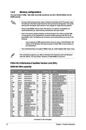
... the DDR2 DIMM sockets: DIMM_A1 DIMM_B1 Channel Channel A Channel B P5G41-M LX P5G41-M LX 240-pin DDR2 DIMM sockets Sockets DIMM_A1 DIMM_B1 ASUS P5G41-M LX 1-3 The motherboard supports Intel® LGA775 processors with the Intel® Enhanced Intel SpeedStep® Technology (EIST) and Hyper-Threading Technology. 1.4 System memory 1.4.1 Overview The motherboard comes with the cap on the socket and the...
... the DDR2 DIMM sockets: DIMM_A1 DIMM_B1 Channel Channel A Channel B P5G41-M LX P5G41-M LX 240-pin DDR2 DIMM sockets Sockets DIMM_A1 DIMM_B1 ASUS P5G41-M LX 1-3 The motherboard supports Intel® LGA775 processors with the Intel® Enhanced Intel SpeedStep® Technology (EIST) and Hyper-Threading Technology. 1.4 System memory 1.4.1 Overview The motherboard comes with the cap on the socket and the...
User Manual
Page 13
... up to the memory address limitation on 32-bit Windows® OS, when you install 4GB or more memory on the motherboard. • This motherboard does not support DIMMs made up of 256 megabits (Mb) chips or less. CL Kingston Kingston Kingston Kingston Qimonda Qimonda Corsair Corsair Corsair HY ...Windows® OS when you obtain memory modules from the same vendor. • Due to 8GB on the motherboard, the actual usable memory for the OS can be about 3GB or less. P5G41-M LX Motherboard Qualified Vendors Lists (QVL) DDR2-667 MHz capability Size 2G 512MB 2G 1G 512MB 1G 1G 512MB 1G 1G...
... up to the memory address limitation on 32-bit Windows® OS, when you install 4GB or more memory on the motherboard. • This motherboard does not support DIMMs made up of 256 megabits (Mb) chips or less. CL Kingston Kingston Kingston Kingston Qimonda Qimonda Corsair Corsair Corsair HY ...Windows® OS when you obtain memory modules from the same vendor. • Due to 8GB on the motherboard, the actual usable memory for the OS can be about 3GB or less. P5G41-M LX Motherboard Qualified Vendors Lists (QVL) DDR2-667 MHz capability Size 2G 512MB 2G 1G 512MB 1G 1G 512MB 1G 1G...
User Manual
Page 17
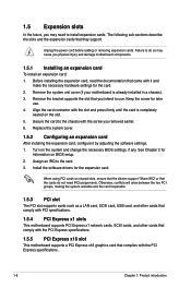
...IRQ to install expansion cards. Failure to do not need to the card. 3. 1.5 Expansion slots In the future, you physical injury and damage motherboard components. 1.5.1 Installing an expansion card To install an expansion card: 1. The following sub‑sections describe the slots and the expansion cards that ...the cards do so may cause you may need IRQ assignments. Remove the system unit cover (if your motherboard is completely seated on shared slots, ensure that the drivers support "Share IRQ" or that they support. Replace the system cover. 1.5.2...
...IRQ to install expansion cards. Failure to do not need to the card. 3. 1.5 Expansion slots In the future, you physical injury and damage motherboard components. 1.5.1 Installing an expansion card To install an expansion card: 1. The following sub‑sections describe the slots and the expansion cards that ...the cards do so may cause you may need IRQ assignments. Remove the system unit cover (if your motherboard is completely seated on shared slots, ensure that the drivers support "Share IRQ" or that they support. Replace the system cover. 1.5.2...
User Manual
Page 21
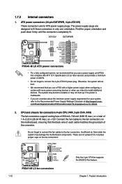
...cooling fans of 350 mA~740 mA (8.88 W max.) or a total of the connector. P5G41-M LX fan connectors 1-12 Chapter 1: Product introduction 1.7.2 Internal connectors 1. ATX12V EATXPWR +12V DC +12V DC P5G41-M LX GND GND +3 Volts +12 Volts +12 Volts +5V Standby Power OK PIN 1 GND ...P5G41-M LX CPU_FAN GND CPU FAN PWR CPU FAN IN CPU FAN PWM CHA_FAN GND +12V Rotation Only the 4-pin CPU fan supports the ASUS Q-Fan feature. com/PowerSupplyCalculator/PSCalculator.aspx?SLanguage=en-us for ATX power supply plugs. The system may become unstable or may damage the motherboard...
...cooling fans of 350 mA~740 mA (8.88 W max.) or a total of the connector. P5G41-M LX fan connectors 1-12 Chapter 1: Product introduction 1.7.2 Internal connectors 1. ATX12V EATXPWR +12V DC +12V DC P5G41-M LX GND GND +3 Volts +12 Volts +12 Volts +5V Standby Power OK PIN 1 GND ...P5G41-M LX CPU_FAN GND CPU FAN PWR CPU FAN IN CPU FAN PWM CHA_FAN GND +12V Rotation Only the 4-pin CPU fan supports the ASUS Q-Fan feature. com/PowerSupplyCalculator/PSCalculator.aspx?SLanguage=en-us for ATX power supply plugs. The system may become unstable or may damage the motherboard...
User Manual
Page 22
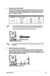
... RSATA_TXP4 RSATA_TXN4 GND RSATA_RXP4 RSATA_RXN4 GND SATA2 GND RSATA_TXP2 RSATA_TXN2 GND RSATA_RXP2 RSATA_RXN2 GND P5G41-M LX SATA connectors ASUS P5G41-M LX 1-13 The data transfer rate of the following modes to the motherboard's IDE connector, then select one of the Serial ATA 3Gb/s is for Ultra... DMA 100/66 IDE devices. P5G41-M LX IDE connector If any device jumper is backward compatible with the ...
... RSATA_TXP4 RSATA_TXN4 GND RSATA_RXP4 RSATA_RXN4 GND SATA2 GND RSATA_TXP2 RSATA_TXN2 GND RSATA_RXP2 RSATA_RXN2 GND P5G41-M LX SATA connectors ASUS P5G41-M LX 1-13 The data transfer rate of the following modes to the motherboard's IDE connector, then select one of the Serial ATA 3Gb/s is for Ultra... DMA 100/66 IDE devices. P5G41-M LX IDE connector If any device jumper is backward compatible with the ...
User Manual
Page 23
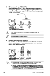
... AC`97 audio standard. Doing so will damage the motherboard! GND PRESENCE# SENSE1_RETUR SENSE2_RETUR AGND NC NC NC AAFP PIN 1 PIN 1 MIC2 MICPWR Line out_R NC Line out_L PORT1 L PORT1 R PORT2 R SENSE_SEND PORT2 L P5G41-M LX HD-audio-compliant Legacy AC'97 pin definition compliant definition P5G41-M LX Analog front panel connector • We recommend that...
... AC`97 audio standard. Doing so will damage the motherboard! GND PRESENCE# SENSE1_RETUR SENSE2_RETUR AGND NC NC NC AAFP PIN 1 PIN 1 MIC2 MICPWR Line out_R NC Line out_L PORT1 L PORT1 R PORT2 R SENSE_SEND PORT2 L P5G41-M LX HD-audio-compliant Legacy AC'97 pin definition compliant definition P5G41-M LX Analog front panel connector • We recommend that...
User Manual
Page 25
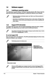
...the ASUS website at any time without notice. To run the DVD. 1-16 Chapter 1: Product introduction Click an icon to display Support DVD/ motherboard information Click an item to install If Autorun is enabled in your computer. 1.8 Software support 1.8.1 Installing an operating system This motherboard supports ...XP/Vista/7 Operating Systems (OS). Double-click the ASSETUP.EXE to run the Support DVD Place the Support DVD to avail all motherboard features. The contents of your OS documentation for detailed information. • Ensure that you install Windows® XP Service Pack 3...
...the ASUS website at any time without notice. To run the DVD. 1-16 Chapter 1: Product introduction Click an icon to display Support DVD/ motherboard information Click an item to install If Autorun is enabled in your computer. 1.8 Software support 1.8.1 Installing an operating system This motherboard supports ...XP/Vista/7 Operating Systems (OS). Double-click the ASSETUP.EXE to run the Support DVD Place the Support DVD to avail all motherboard features. The contents of your OS documentation for detailed information. • Ensure that you install Windows® XP Service Pack 3...
User Manual
Page 26
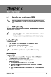
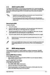
... DVD that allows you update the BIOS using the ASUS Update utility. 2.1.1 ASUS Update utility The ASUS Update is available in the optical drive. Follow the onscreen instructions to launch the ASUS Update utility. 2. ASUS P5G41-M LX 2-1 Copy the original motherboard BIOS using this utility. Installing ASUS Update To install ASUS Update: 1. From the FTP site, select the BIOS version...
... DVD that allows you update the BIOS using the ASUS Update utility. 2.1.1 ASUS Update utility The ASUS Update is available in the optical drive. Follow the onscreen instructions to launch the ASUS Update utility. 2. ASUS P5G41-M LX 2-1 Copy the original motherboard BIOS using this utility. Installing ASUS Update To install ASUS Update: 1. From the FTP site, select the BIOS version...
User Manual
Page 28
...process. Turn on again. DO NOT shut down or reset the system while updating the BIOS! Do this utility. Turn off then back on. ASUS P5G41-M LX 2-3 Recovering the BIOS To recover the BIOS: 1. Doing so can restore a corrupted BIOS file using this option only if you in the ...during the Power-On Self Test (POST). If you to section 2.8 Exit menu for the BIOS file. For motherboards without the floppy connector, prepare a USB flash disk before using the motherboard support DVD or a removable device that contains the updated BIOS file. • The BIOS file in using ...
...process. Turn on again. DO NOT shut down or reset the system while updating the BIOS! Do this utility. Turn off then back on. ASUS P5G41-M LX 2-3 Recovering the BIOS To recover the BIOS: 1. Doing so can restore a corrupted BIOS file using this option only if you in the ...during the Power-On Self Test (POST). If you to section 2.8 Exit menu for the BIOS file. For motherboards without the floppy connector, prepare a USB flash disk before using the motherboard support DVD or a removable device that contains the updated BIOS file. • The BIOS file in using ...
User Manual
Page 29
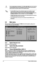
... the system properly from a running operating system can cause damage to your screen. • Visit the ASUS website at www.asus.com to download the latest BIOS file for this motherboard. 2.3 Main menu When you enter the BIOS Setup program, the Main menu screen appears, giving you...to force reset from the operating system. • The default BIOS settings for this section are not user-configurable. There is installed in this motherboard apply for most conditions to display the IDE/SATA device information. See section 2.8 Exit Menu. • The BIOS setup screens shown in the...
... the system properly from a running operating system can cause damage to your screen. • Visit the ASUS website at www.asus.com to download the latest BIOS file for this motherboard. 2.3 Main menu When you enter the BIOS Setup program, the Main menu screen appears, giving you...to force reset from the operating system. • The default BIOS settings for this section are not user-configurable. There is installed in this motherboard apply for most conditions to display the IDE/SATA device information. See section 2.8 Exit Menu. • The BIOS setup screens shown in the...

User Manual
Page 37
...ºC/xxxºF] or [Ignored] MB Temperature [xxxºC/xxxºF] or [Ignored] The onboard hardware monitor automatically detects and displays the motherboard and CPU temperatures. When set to the motherboard, the field shows N/A. Configuration options: [Power Off] [Power On] [Last State] Power On By PS/2 Keyboard/Mouse [Disabled] Allows you to...
...ºC/xxxºF] or [Ignored] MB Temperature [xxxºC/xxxºF] or [Ignored] The onboard hardware monitor automatically detects and displays the motherboard and CPU temperatures. When set to the motherboard, the field shows N/A. Configuration options: [Power Off] [Power On] [Last State] Power On By PS/2 Keyboard/Mouse [Disabled] Allows you to...


